Table of Contents
Advertisement
Quick Links
690/690F, 790/790F and 693/793 Security Command
Description
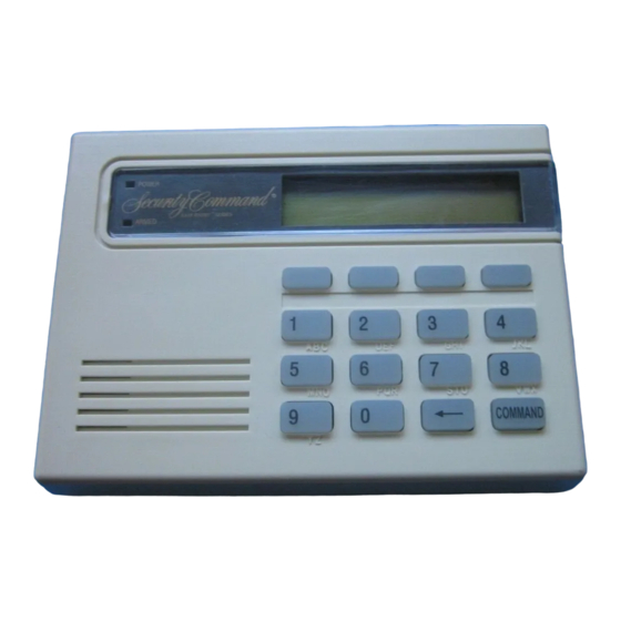
The DMP 690/690F, 790/790F and 693/793 Security Command™ LCD Keypads are the industry's first burglary/fire
keypads with integrated access control capability. Each keypad provides four 2-button Panic keys, an AC power
LED, an Armed LED, 32-character display, backlit keyboard with easy-to-read lettering and an internal speaker. In
addition, the Models 790/790F and 793 keypads also provide four fully programmable Class B, Style A protection
zones you can program for a variety of burglary, fire, and access control applications.
The 693 and 793 keypads provide a built-in proximity card reader designed to read HID 1300 Series proximity
credentials. The Model 793 keypad also provides a door strike relay and allows Wiegand input from HID, DMP, or
other external card readers. When presenting a DMP credential use the keypad built-in card reader. HID credentials
can be read at either the keypad or the external card reader.
Note: The 690F and 790F Security Command LCD keypads do not provide an Armed LED. These keypads may be
installed in fire only applications.
Installing the Keypad
The keypads each use the same plastic housing. They are all designed to easily install on any 4" square box, 3-gang
switch box, 695 and 696 backbox, or flat surface. Figure 1 shows the keypad housing base mounting hole locations.
Removing the Base
The keypad housing is made up of two parts: the front, which contains the circuit board
and other components, and the base. To mount the keypad, remove the base from the
front by inserting a flat screwdriver into one of the openings on the bottom. Twist the
screwdriver while pulling the halves apart. Repeat with the other opening.
Harness Wiring
Figure 1 shows wiring harness assignments. Observe wire colors when connecting the red, yellow, green, and black
wires to the keypad bus. When wiring directly to the panel terminals, connect red to panel terminal 7, yellow to
terminal 8, green to 9, and black to panel terminal 10. Use 1k Ohm EOL resistors, DMP Model 311, on keypad zones
1 through 4.
The 690, 690F, and 693 keypads are supplied with a 4-wire harness for panel keypad bus connection.
The 790, 790F, and 793 keypads are supplied with a 12-wire data bus/zone harness. Four wires connect to the
keypad bus, the same way the 690 and 690F keypad harness connects. The remaining eight wires are for the four
zone inputs: two wires for each zone.
The 793 keypad is also supplied with one 5-wire output/reader harness.
Surface and Backbox
Combined 4-square
and 3-gang switch box
Keypad Back
Surface and Backbox
Mounting Holes
Mounting Holes
Mounting Holes
Figure 1: Keypad Back Showing Wiring Harness Assignments
INST ALLA TION GUIDE
Green/White – Connect Reader Data 0
White – Connect Reader Data 1
Orange – Door Strike Normally Open
Gray – Door Strike Common
Violet – Door Strike Normally Closed
Yellow/White
1K EOL
White/Yellow
Orange White
1K EOL
White/Orange
Red/White
1K EOL
White/Red
Brown/White
1K EOL
White/Brown
Black – Ground
Green – Receive Data
Yellow – Send Data
Red – Keypad Power
™
Keypads
Output Reader
793 Keypad
– Zone 4
– Zone 3
Zones 1 through 4
790/790F, and 793
Keypads
– Zone 2
– Zone 1
All Keypads
Advertisement
Table of Contents

Subscribe to Our Youtube Channel
Related Manuals for DMP Electronics Security Command 690


Summary of Contents for DMP Electronics Security Command 690
- Page 1 INST ALLA TION GUIDE ™ 690/690F, 790/790F and 693/793 Security Command Keypads Description The DMP 690/690F, 790/790F and 693/793 Security Command™ LCD Keypads are the industry’s first burglary/fire keypads with integrated access control capability. Each keypad provides four 2-button Panic keys, an AC power LED, an Armed LED, 32-character display, backlit keyboard with easy-to-read lettering and an internal speaker.
-
Page 2: Additional Power Supply
Additional Power Supply If the current draw for all keypads exceeds the panel output, you can provide additional current by adding a Model 505-12 auxiliary power supply. Connect all keypad common wires to the power supply negative terminal. Run a jumper wire from the power supply negative terminal to the panel common terminal. -
Page 3: Panic Key Options
793 Door Strike Relay Operation As soon as the user code sent from the reader is verified by the panel, the keypad Door Strike relay activates for five seconds. During this time, the access door connected to Zone 2 must be opened to start the programmed entry/exit timer and zone soft shunt. -
Page 4: End-User Options
End-User Options The LCD Keypads provide three keypad adjustments the end-user can make through a User Options Menu. The user can also view the keypad model number and address in User Options. On all keypads press and hold the Back Arrow (<—) and CMD (COMMAND) keys for two seconds to access User Options. The keypad display changes to SET BRIGHTNESS. -
Page 5: Installer Options Menu
Installer Options Menu The LCD keypads provide Keypad Option and Keypad Diagnostic menus to allow installers and service technicians to configure and test keypad operation. Accessing Installer Options You can only access the Installer Options Menu through the User Options function. Hold down the <— and CMD keys for two seconds to display SET BRIGHTNESS. - Page 6 Zone 2 Soft-Shunt Time (793 only) ZONE 2 SOFTSHUNT TIME: 40 Enter the number of Soft-Shunt seconds to elapse before the Soft-Shunt timer expires. Range is from 20 to 250 seconds. Press any top row select key to enter the number of seconds.
- Page 7 Custom Card Definitions (693 and 793 only) WIEGAND CODE LENGTH: 45 When using a custom credential, enter the total number of bits to be received in Wiegand code including parity bits. Press any top row Select key to enter a number between 0-255 to equal the number of bits.
- Page 8 Number of User Code Digits (693 and 793 only) NO. OF USER CODE DIGITS: 5 The keypad recognizes user codes from four to six digits in length. Press any Select key to enter the user code digit length being used by the panel. Default is 5. When searching the bit string from the reader for the user code, the digits are identified and read from left to right.
- Page 9 Accessing Keypad Diagnostics If necessary, refer to Access the User Menu on the previous page. Keypad Diagnostics (KPD DIAG) KPD KPD The Keypad Diagnostic option allows you to check the display segments, check the OPT DIAG STOP keyboard backlighting, and test individual keys. Press the Select key under KPD DIAG.
-
Page 10: Keypad Arming And Disarming
693/793 User’s Guide There are three different sections: Keypad Arming and Disarming, Keypad Door Strike, and Keypad Entry Delay. All of the examples below assume that CLOSING CODE is YES in panel programming. Keypad Arming and Disarming Area System Arming and Disarming Press CMD, the keypad displays ARM DISARM. -
Page 11: Keypad Door Strike
Keypad Door Strike Area and All/Perimeter Door Strike From the Status List, present your card to the reader. Once validated by the system, all areas assigned to your code arm or disarm automatically and the 793 keypad Door Strike relay activates. Home/Away systems only activate the 793 Door Strike relay when arming and disarming. -
Page 12: Fcc Information
FCC Information This device complies with Part 15 of the FCC Rules. Operation is subject to the following two conditions: (1) This device may not cause harmful interference, and (2) this device must accept any interference received, including interference that may cause undesired operation. Changes or modifications made by the user and not expressly approved by the party responsible for compliance could void the user’s authority to operate the equipment.
Need help?
Do you have a question about the Security Command 690 and is the answer not in the manual?
Questions and answers
How do you change the user code
To change the user code on the DMP Electronics Security Command 690 keypad:
1. Access the user code settings.
2. Select the number of digits for the user code (4 to 6 digits, default is 5).
3. Enter the new user code.
4. Save the changes by pressing the appropriate command (CMD) key.
The keypad will recognize the new user code based on the selected digit length.
This answer is automatically generated