Table of Contents
Advertisement
Advertisement
Table of Contents

Related Manuals for DMP Electronics 9800INT Series


Summary of Contents for DMP Electronics 9800INT Series
- Page 1 9800INT Series Graphic Touchscreen Keypad INSTALLATION AND PROGRAMMING GUIDE...
-
Page 3: Table Of Contents
TABLE OF CONTENTS About the Keypad ........1 Program the Keypad ........ 17 Keypad Options ............. 17 Keypad Features .........2 Default Keypad Message ..........17 Programmable Carousel Menu ......... 3 Arm Panic Keys ..............17 Arming/Disarming Wait Time ........18 Number Pad Features ........4 Enable Tamper ..............18 Card Formats ..............19 Select a Location ........7... - Page 4 End User Training ........31 Access the User Menu ..........31 Arm and Disarm the System ........32 Touchless Arming ............33 Use Access Control .............33 Icon Reference ..............36 Change System Wi-Fi Password ......38 Clean the Keypad ............40 Replace the Keypad Battery ........41 Public Card Formats .......
-
Page 5: About The Keypad
ABOUT THE KEYPAD 9862INT Series Wireless Graphic Touchscreen Keypads offer flexible features and functionality. Each keypad provides: • AC Power/Armed LED • Full color touchscreen display • Built-in proximity card reader • Internal speaker • Wireless communication • Internal rechargeable 3.7 V lithium battery •... -
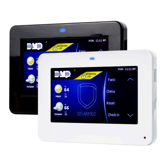
Page 6: Keypad Features
KEYPAD FEATURES Armed/Power LEDs & Proximity Reader Dealer Logo Carousel Menu microSD Card Slot Interactive Arming/ Disarming Shield Press the Navigation Arrows or touch and drag the menu to scroll Local Weather Figure 1: Keypad Features 9862INT Series Installation and Programming Guide... -
Page 7: Programmable Carousel Menu
Programmable Carousel Menu The carousel menu allows the user to pick and choose what displays within the carousel menu on the home screen. Press Options in the carousel menu. From here, adjust the keypad screen brightness, keypad tone, and keypad volume. Press a box under Display In Menu to select that option to display in the carousel menu. -
Page 8: Number Pad Features
NUMBER PAD FEATURES Return to Home Screen Select Areas Back Arrow Figure 3: Number Pad 9862INT Series Installation and Programming Guide... - Page 9 Number Pad Choose a character from the table. Use the Greek Characters table if Greek was selected as the keypad language setting. Refer to Select Language. See Table 1. Identify the Number the character correlates with and press that number on the number pad.
- Page 10 Return to Home Screen Select Areas Special Characters Uppercase/ Lowercase Letters Number Pad Figure 4: Number Pad Figure 5: Standard Keyboard 9862INT Series Installation and Programming Guide...
-
Page 11: Select A Location
SELECT A LOCATION 9862INT Series Wireless Graphic Touchscreen Keypads provide a built–in survey capability to allow one person to confirm keypad communication with the wireless receiver or panel. This allows you to determine the best location for the keypad. Press Options in the carousel menu. Press the installer options icon at the bottom-left corner of the screen. -
Page 12: Install The Keypad
INSTALL THE KEYPAD Remove the Cover The keypad housing is made up of two parts: Cover the cover, which contains the circuit board and components, and the base. Insert a flat screwdriver into one of the slots on the bottom of the keypad and lift the screwdriver upward. -
Page 13: Power The Keypad
Power the Keypad Connect the DC power supply positive and negative wires to the PCB terminal block. See Figure 7. In addition to powering the keypad, the power supply also charges the internal back-up battery. Warning: Observe Polarity. Connect the black (-) wire to the negative terminal on the power supply. - Page 14 Standby Battery The keypad rechargeable battery provides 12 hours of backup battery power when primary AC power is not available. It is shipped already installed inside the keypad. The battery is intended for backup power only and not to operate the keypad on a daily basis. If the battery is low, or not plugged into the internal battery connector, a low battery condition is indicated by the panel.
- Page 15 Warning: Risk of fire, explosion, and burns. Do not disassemble, heat above 212°F (100°C), or incinerate. Battery Connection Battery Figure 8: Battery Connection 9862INT Series Installation and Programming Guide...
-
Page 16: Mount The Keypad
Mount the Keypad Secure the keypad base to the wall ensuring that the wall tamper switch makes proper contact with the wall. Use the supplied screws in the mounting hole locations. See Figure 9 for mounting hole locations. Note: For Security Grade Surface and Backbox Mounting Holes 2, Environmental Class II Tamper Puck... -
Page 17: Connect The Keypad
Connect the Keypad Connect the keypad to the panel by using one of the following options: Wireless Keypad Association, Auto Pairing, or manually at the keypad in Device Setup. A maximum of seven keypads can be paired with each panel. Wireless Keypad Association XTLplusINT/XTLtouchINT Press Options in the carousel menu. - Page 18 Auto Pair Auto pairing automatically connects your keypad to the panel. After powering the XTLplusINT or XTLtouchINT and the keypad, the keypad displays Pairing Keypad With System... and a ten minute pairing timer begins. Confirmed: The keypad home screen displays, signaling that pairing is complete. Faulty: The keypad displays Pairing Failed, followed by the Reset screen.
-
Page 19: Program The Panel
PROGRAM THE PANEL If using an XT Series International Panel, enter 665 (PRO) then press CMD at the keypad to access the PROGRAMMER menu. If using an XR Series International Panel, enter 6653 (PROG) then press CMD. After completing each of the following steps, press CMD to advance to the next option. Refer to the panel programming guide as needed. -
Page 20: Device Type
Device Type DEVICE SETUP For use as a standard keypad, select KPD. For use as an access TYPE: KEYPAD control keypad, press any select area, then select DOOR. Communication Type DEVICE SETUP Press any select area, then select WLS (Wireless) as the COMM TYPE: communication type. -
Page 21: Program The Keypad
PROGRAM THE KEYPAD Refer to the appropriate panel programming guide as needed. Keep in mind that operation for some programming options is restricted to the appropriate model. To access the Keypad Options menu, press Options in the carousel menu. Press the Installer Options or wrench icon and enter 3577 (INST) and press CMD. -
Page 22: Arming/Disarming Wait Time
Arming/Disarming Wait Time ALL?: NO YES Select the number of seconds (1-9) the keypad should wait DELAY: to arm and disarm when an area system displays ALL? NO YES or a H/S/A system waits during arming only. If NO or YES, or HOME, SLEEP, or AWAY is not manually selected before the delay expires, the keypad automatically selects YES or AWAY. -
Page 23: Card Formats
Card Formats CARD FORMATS Select DMP to allow credentials that use a 26-45 bit data FORMAT NO: string. The menu advances to REQUIRE SITE. Select CUSTOM to disable DMP format and program slots 1-8 as needed. The menu advances to FORMAT NO. Select ANY to allow all Wiegand card reads to activate the door strike relay. - Page 24 Card Format Number CARD FORMATS Select the slot number (1-8) that you want to program FORMAT NO: for a custom non-DMP card format. The format that is programmed into slot 1 is the default format. In the event that a card with an unrecognized format is used, that card will be read in the format that is programmed in slot 1.
- Page 25 Wiegand Code Length WIEGAND CODE When using a custom credential, enter the total number of LENGTH: bits to be received in Wiegand code including parity bits. Press any select area to enter a number between 1-255 to equal the number of bits. Default is 26 bits. An access card contains data bits for a site code, user code, and start/stop/parity bits.
- Page 26 Site Code Position and Length SITE CODE Enter the site code position and length in the data string. POS: 1 LEN: 8 Press select area 2 to clear the site code start position. Enter a number between 0-255. Press CMD to save. Default is 1. Press select area 4 to clear the site code length and enter a number between 1-24.
-
Page 27: Require Site Code
Require Site Code REQUIRE SITE Press the select area under YES to use a site code and press CODE: NO CMD to view the site code entry display. Press NO to advance to NO OF USER CODE DIGITS. Default is NO. In addition to user code verification, door access is only granted when any one site code programmed at the SITE CODE ENTRY matches the site code received in the Wiegand... -
Page 28: No Communication With Panel
Number of User Code Digits NO OF USER CODE The keypad recognizes user codes from 4-10 digits long. DIGITS: Press any top row select key or area to enter a user code digit length. This number must match the user code number length being programmed in the panel. - Page 29 Press the first select key or area to choose OFF (Relay SITE ANY ON Always Off). The relay does not turn on when any Wiegand string is received. OFF does not affect any REX operation. If communication is lost during a door strike, the relay remains on for the door strike duration but turns off at the end of the door strike timer.
-
Page 30: System Type
System Type SYSTEM OPTIONS Program the keypad as the same system type selected in AREA A/P H A/A HSA panel programming. Dealer Logo DEALER LOGO Use this option to add a custom dealer logo to the main DELETE screen of the keypad. Prior to selecting ADD, insert a microSD card containing the logo file in to the slot on the right side of the keypad. -
Page 31: Carousel Z-Wave Items
Figure 11: Inserting a microSD Card Carousel Z-Wave Items Carousel Z-Wave Items allows you to select the Z-Wave options to display in the carousel menu. Press an item to select and a check–mark displays. Press again to deselect that option. Items for the carousel include Lights, Doors, Thermostats, and Favorites. -
Page 32: Shortcut Items
Shortcut Items Shortcut Items allows you to select additional menu items to display in the carousel menu. Press the item to select and a checkmark displays. Press again to deselect that option. Items for the carousel include User Codes, Schedules, and Events. Default is no items selected. -
Page 33: Additional Programming
ADDITIONAL PROGRAMMING Update the Keypad Technicians can initiate a firmware update from a microSD card using RESTART KEYPAD. This process takes 5 minutes to complete. Update Keypad Firmware Using Restart Navigate to DMP.com/Dealer_Direct and select Software Downloads from the menu. Select a software update. Figure 15: Restart Keypad Select Download. -
Page 34: Test The Keypad
TEST THE KEYPAD Test the keypad to ensure keypad lighting, individual shortcut keys, and any programmed zones work properly. Access the Keypad Diagnostics menu by pressing Options in the carousel menu. Press the Installer Options or wrench icon and enter 3577 (INST) and press CMD. -
Page 35: End User Training
END USER TRAINING This section contains instructions on how users can arm and disarm their system, use access control, and entry delay. All of the examples displayed assume that CLOSING CODE is YES in panel programming. For more information about using your system, refer to the appropriate system user guides from DMP.com/guides: Access the User Menu In the Carousel Menu, select Keypad. -
Page 36: Arm And Disarm The System
Arm and Disarm the System Area System Type Tap the home screen shield in the center of the keypad. Tap your preferred option. If arming, the keypad displays ALL? NO YES. Select NO to arm individual areas. Select YES to arm all areas. If disarming, the keypad displays ENTER CODE: -. -
Page 37: Touchless Arming
Touchless Arming Present a credential to the built-in reader to automatically arm the system without touching the keypad. After the arming delay expires, All/Perimeter systems arm All. Home/Sleep/Away and Home/Away systems arm Away. Use Access Control Area System Arming and Disarming Present your credential to the reader. - Page 38 All/Perimeter System Arming and Disarming • Arming: Present your card to the reader. PERIM ALL displays. Tap the preferred option. The system arms according to the option you selected. Disarming: Present your card to the reader. The system disarms. • Home/Sleep/Away and Home/Away System Arming and Disarming Arming: Present your card to the reader.
- Page 39 Use Entry Delay When Disarming After the entry delay starts, the keypad sounds an entry tone and displays ENTER CODE. Present your credential to the reader. Once validated, the system disarms all areas accessible by the credential. Refer to Figure 18. Entry delay starts.
-
Page 40: Icon Reference
Icon Reference Arming Shield Icons Quick Arm Armed Alarm Home Sleep Away Perimeter All System Burglary Fire Ready To Exit Exit Timer Popups Menu Enter Code Arm Instant Attention List Alert Home Installer Navigation Edit Arming Options Panic Options Home Sleep Away All System... - Page 41 Z-Wave Lights Appliances Doors Garage Door Favorites Z-Wave Thermostats Controls Decrease Increase Auto Heat Cool Room Temp Status Bar Header System Ready Attention List Armed (Area) Home Sleep Away Perimeter All System Chime Battery Trouble AC Trouble Wi-Fi 9862INT Series Installation and Programming Guide...
-
Page 42: Change System Wi-Fi Password
Change System Wi-Fi Password When you change your network’s Wi-Fi password, the system detects that the password has changed and asks you to update it. To close the Incorrect WiFi Password dialog and return to the main menu, tap the Shield icon. To reopen the dialog from the main menu, tap the Wireless icon. - Page 43 Figure 19: Incorrect Wi-Fi Password Dialog Figure 20: Enter Wi-Fi Password Screen 9862INT Series Installation and Programming Guide...
-
Page 44: Clean The Keypad
Clean the Keypad Failure to follow cleaning recommendations may result in equipment damage. • Do not use harsh cleaners to clean keypad surfaces. • Do not oversaturate cleaning cloths or allow cleaner to make contact with internal electronic components, cables, or power sources. •... -
Page 45: Replace The Keypad Battery
Replace the Keypad Battery Disconnect the battery lead connector from the keypad battery header. Remove the standby battery from the PCB. Observe polarity and connect the battery lead connector to the keypad battery header. Place the new battery on the keypad PCB using double-sided sticky tape. See Figure 21. -
Page 46: Public Card Formats
PUBLIC CARD FORMATS WIEGAND SITE CODE SITE CODE USER CODE USER CODE USER CODE CARD FORMAT CODE POSITION LENGTH POSITION LENGTH DIGITS LENGTH H10301 26 BIT H10302 37 BIT W/O H10304 37 BIT W/FAC FARPOINTE 39 BIT CORPORATE 1000 35 BIT CORPORATE 1000 48 BIT 9862INT Series Installation and Programming Guide... -
Page 47: Credentials
CREDENTIALS 125 kHz PROXIMITY CREDENTIALS PSC-1 Standard Light Proximity Card PSK-3 Proximity Key Ring Tag PSM-2P ISO Imageable Proximity Card 1306 Prox Patch™ 1326 Proxcard II® Card 1346 ProxKey III® Access Device 1351 ProxPass® 1386 IsoProx II® Card 9862INT Series Installation and Programming Guide... -
Page 48: Ordering Information
ORDERING INFORMATION Keypads 9862-W Graphic Touchscreen Keypad (white, prox reader) Accessories Wiring Harnesses and Transformers 300-9800-4 Replacement 4-Wire Keypad Harness 300-9800-PWR Replacement Power Harness (Hardware Level 101 and higher) Backboxes, Mounting Plates, and Stands 9800-STAND-B/10 Replacement Deskstand for 9800 Keypads (black, 10 pack) 9800-STAND-W/10 Replacement Deskstand for 9800 Keypads (white, 10 pack) Batteries... -
Page 49: Compliance Specifications
COMPLIANCE SPECIFICATIONS Specifications Operating Voltage 12 VDC Operation 868 MHz Standby Current 120 mA at 12 VDC Alarm Current 206 mA at 12 VDC (Peak) Dimensions 17.78 cm W x 13.335 cm H x 1.27cm D Weight 0.43 kg Security Grade 2 Type B ACE Environment Class Operating Temperature 0 °C to 49 °C... -
Page 50: International Certifications
INTERNATIONAL CERTIFICATIONS Security Grade: Environmental Class: Intertek (ETL) EN 50131-1 Alarm Systems. Intrusion and Hold-up Systems. System Requirements EN 50131-5 Interconnections Equipment Using Radio Frequency Techniques EN 50136-1 Alarm Transmission Systems and Equipment EN 50136-2 Alarm Systems - Alarm Transmission Systems and Equipment Part 2:Requirements for Supervised Premises Transceiver (SPT) EN 50130-5 Environmental Standards... - Page 52 LT-1367INT 20291 1.01 © 2020 Digital Monitoring Products, Inc.
Need help?
Do you have a question about the 9800INT Series and is the answer not in the manual?
Questions and answers