
Related Manuals for AXIOMTEK ETM830 Series


Summary of Contents for AXIOMTEK ETM830 Series
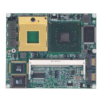
- Page 1 ETM830 Series ® Intel Yonah & Merom ETX v3.01 SoM Multiple I/O Features With User’s Manual...
- Page 2 AXIOMTEK does not warrant or assume any legal liability or responsibility for the accuracy, completeness or usefulness of any information in this document. AXIOMTEK does not make any commitment to update the information in this manual.
-
Page 3: Esd Precautions
Wear a wrist-grounding strap, available from most electronic component stores, when handling boards and components. Trademarks Acknowledgments AXIOMTEK is a trademark of AXIOMTEK Co., Ltd. ® Windows is a trademark of Microsoft Corporation. Phoenix & AWARD are trademarks of Phoenix Technology Ltd. -
Page 4: Table Of Contents
Table of Contents Disclaimers ......................ii ESD Precautions ....................iii Chapter 1 Introduction ..............1 Specifications ..................2 Utilities Supported ................... 4 Chapter 2 Board Layout and Connectors ........5 Board Layout and Fixing Holes ............... 5 Board Dimensions ................... 7 Heatspreader Installation ................ -
Page 5: Chapter 1 Introduction
C h a p t e r 1 Introduction The ETM830 Series is a finest embedded ETX computer-on-module in the market, which makes a generic interface to connect the module to peripherals such as hard disk, mouse, and display. It supports ®... -
Page 6: Specifications
ETM830 All-In-One ETX v3.01 SoM User’s Manual Specifications ® CPU: Socket M (478) for Intel Yonah & Merom processors CPU Frequency: FSB533/667MHz ® System Chipset: Intel 945GME and ICH*7M BIOS Phoenix-Award BIOS, Y2K compliant 4Mbit Flash, DMI, Plug and Play PXE Ethernet Boot ROM SmartView for multiple LCD type selection, display mode option and application extension features... - Page 7 ETM830 All-In-One ETX v3.01 SoM User’s Manual Expansion Interface Four PCI Bus Masters supported One Full ISA supported Ethernet One RTL8139DL Fast Ethernet controller Audio 5.1 channel AC'97 Codec Audio (optional) Realtek ALC655, AC'97 audio CODEC through ETX connector MIC-in, Line-in, Line-out Power Management ACPI (Advanced Configuration and Power Interface) Form Factor...
-
Page 8: Utilities Supported
ETM830 All-In-One ETX v3.01 SoM User’s Manual Utilities Supported Chipset Driver VGA Driver Ethernet Driver Audio Driver Introduction... -
Page 9: Chapter 2 Board Layout And Connectors
ETM830 All-In-One ETX v3.01 SoM User’s Manual C h a p t e r 2 Board Layout and Connectors Board Layout and Fixing Holes Component Side Jumpers and Connectors... - Page 10 ETM830 All-In-One ETX v3.01 SoM User’s Manual Solder Side Jumpers and Connectors...
-
Page 11: Board Dimensions
ETM830 All-In-One ETX v3.01 SoM User’s Manual Board Dimensions Component Side Jumpers and Connectors... - Page 12 ETM830 All-In-One ETX v3.01 SoM User’s Manual Solder Side Jumpers and Connectors...
-
Page 13: Heatspreader Installation
ETM830 All-In-One ETX v3.01 SoM User’s Manual Heatspreader Installation There is a protective plastic covering on the thermal pads. This must be removed before the heatspreader can be mounted. Each heatspreader is designed for a specific ETM module. The thermal pads on the heatspreader are designed to make contact with the necessary components on the ETM module. - Page 14 ETM830 All-In-One ETX v3.01 SoM User’s Manual Figure 2: ETM830 Thermal Solution Design Guide Jumpers and Connectors...
-
Page 15: Connectors
Connectors connect the CPU card with other parts of the system. Loose or improper connection might cause problems. Make sure all connectors are properly and firmly connected. Here is a summary table shows you all connectors on the ETM830 Series. Connectors Label... -
Page 16: Etx Connector - X1: Cns3
ETM830 All-In-One ETX v3.01 SoM User’s Manual 2.4.1 ETX Connector – X1: CNS3 Description Description PCICLK3 PCICLK4 PCICLK1 PCICLK2 PCI_REQ3# PCI_GNT3# PCI_GNT2# VCC3 PCI_REQ2# PCI_GNT1# PCI_REQ1# VCC3 PCI_GNT0# SERIRQ PCI_REQ0# PCI_AD0 VCC3 PCI_AD1 PCI_AD2 PCI_AD4 PCI_AD3 PCI_AD6 PCI_AD5 PCI_C/BE0# PCI_AD7 PCI_AD8 PCI_AD9 PCI_AD10... - Page 17 ETM830 All-In-One ETX v3.01 SoM User’s Manual Description Description PCI_PERR# PCI_PME# USB2- PCI_LOCK# PCI_DEVSEL# PCI_TRDY# USB3- PCI_IRDY# PCI_STOP# PCI_FRAME# USB2+ PCI_AD16 PCI_C/BE2# PCI_AD17 USB3+ PCI_AD19 PCI_AD18 PCI_AD20 USB0- PCI_AD22 PCI_AD21 PCI_AD23 USB1- PCI_AD24 PCI_C/BE3# PCI_AD25 PCI_AD26 PCI_AD28 USB0+ PCI_AD27 PCI_AD29 PCI_AD30 USB1+ PCI_RST#...
-
Page 18: Etx Connector - X2: Cns1
ETM830 All-In-One ETX v3.01 SoM User’s Manual 2.4.2 ETX Connector – X2: CNS1 Description Description ISA_SD14 ISA_SD15 ISA_SD13 MASTER# ISA_SD12 DREQ7 ISA_SD11 DACK7# ISA_SD10 DREQ6 ISA_SD9 DACK6# ISA_SD8 DREQ5 ISA_MEMW# DACK5# ISA_MEMR# DREQ0 ISA_LA17 DACK0# ISA_LA18 IRQ14 ISA_LA19 IRQ15 ISA_LA20 IRQ12 ISA_LA21 IRQ11... - Page 19 ETM830 All-In-One ETX v3.01 SoM User’s Manual Description Description ISA_SA7 IRQ6 ISA_SA8 IRQ7 ISA_SA9 SYSCLK ISA_SA10 REFRESH# ISA_SA11 DREQ1 ISA_SA12 DACK1# ISA_SA13 DREQ3 ISA_SA14 DACK3# ISA_SA15 IOR# ISA_SA16 IOW# ISA_SA18 ISA_SA17 ISA_SA19 SMEMR# IOCHRDY ISA_SD0 SMEMW# ISA_SD2 ISA_SD1 ISA_SD3 N0WS# DREQ2 ISA_SD4 ISA_SD5...
-
Page 20: Etx Connector - X3: Cns4
ETM830 All-In-One ETX v3.01 SoM User’s Manual 2.4.3 ETX Connector – X3: CNS4 Description Description BLUE HSYNC GREEN VSYNC DDCK DDDA LVDSB_CLK- LVDSB_DATA3- LVDSB_CLK+ LVDSB_DATA3+ LVDSB_DATA1+ LVDSB_DATA2+ LVDSB_DATA1- LVDSB_DATA2- LVDSA_DATA3- LVDSB_DATA0+ LVDSA_DATA3+ LVDSB_DATA0- LVDSA_DATA2- LVDSA_CLK+ LVDSA_DATA2+ LVDSA_CLK- LVDSA_DATA0+ LVDSA_DATA1+ LVDSA_DATA0- LVDSA_DATA1- L_DDC_DAT L_DDC_CLK... - Page 21 ETM830 All-In-One ETX v3.01 SoM User’s Manual Description Description PD7/N.C IRRX ERR#/HDSEL# IRTX PD6/N.C RXD2 INIT#/DIR# RTS2# PD5/N.C DTR2# SLIN#/STEP# DCD2# PD4/DSKCHG# DSR2# PD3/RDATA# CTS2# PD2/WP# TXD2# PD1/TRK0# RI2# PD0/INDEX# RXD1 ACK#/DRV RTS1# BUSY#/MOT DTR1# PE/WDATA# DCD1# SLCT#/WGATE# DSR1# MSCLK CTS1# MSDAT TXD1#...
-
Page 22: Etx Connector - X4: Cns2
ETM830 All-In-One ETX v3.01 SoM User’s Manual 2.4.4 ETX Connector – X4: CNS2 Description Description 5VSB PWGIN PS_ON SPEAKER PWRBTN# RTC_BATTERY RSMRST# ACTLED SPEEDLED I2CLK OVCR# SMBDAT SMBCLK SMBDAT DASP_S PIDE_CS3# PIDE_CS1# PIDE_A2# PIDE_A0# PIDE_A1# PIDE_INTRQ PIDE_ACK# PIDE_RDY PIDE_IOR# PIDE_IOW# Jumpers and Connectors... - Page 23 ETM830 All-In-One ETX v3.01 SoM User’s Manual Description Description PIDE_DRQ PIDE_D15 PIDE_D0 PIDE_D14 PIDE_D1 PIDE_D13 PIDE_D2 PIDE_D12 PIDE_D3 PIDE_D11 PIDE_D4 PIDE_D10 PIDE_D5 PIDE_D9 PIDE_D6 RING# CBLID_P# LAN_RX- PIDE_D8 LAN_RX+ LAN_TX- PIDE_D7 LAN_TX+ HDRST# -- End of ETX Connector-X4 (CNS2) Pin Assignment Table -- Jumpers and Connectors...
-
Page 24: 7-Pin Sata Connectors: Sata1, Sata2
ETM830 All-In-One ETX v3.01 SoM User’s Manual 2.4.5 7-pin SATA Connectors: SATA1, SATA2 These SATA connectors are for high-speed SATA interface ports and they can be connected to hard disk devices. SATA1,SATA2 Description 2.4.6 Audio Connector: SFC1 The audio connector is for six channel AC’97 interface ports and they can be connected to audio jack. -
Page 25: Chapter 3 Hardware Description
Make sure all correct settings are arranged for your installed microprocessor to prevent the CPU from damages. BIOS The ETM830 Series uses Award Plug and Play BIOS with a single 4Mbit Flash EPROM. System Memory The ETM830 Series industrial CPU card supports one 200-pin DDR2 400/533/667 MHz SODIMM sockets for a maximum memory of 2GB DDR2 SDRAMs. -
Page 26: I/O Port Address Map
ETM830 All-In-One ETX v3.01 SoM User’s Manual I/O Port Address Map ® The Intel Yonah & Merom CPUs can communicate via I/O ports. There are total 1KB port addresses available for assignment to other devices via I/O expansion cards. Address Devices 000-00F Direct memory access controller... - Page 27 ETM830 All-In-One ETX v3.01 SoM User’s Manual Address Devices 3F0-3F5 Standard floppy disk controller Primary IDE Channel Standard floppy disk controller 3F8-3FF Communications Port (COM1) 4D0-4D1 Motherboard resources 680-6FF Motherboard resources 778-77B Printer Port (LPT1) 880-88F Motherboard resources A78-A7B Motherboard resources B78-B7B Motherboard resources BBC-BBF...
-
Page 28: Interrupt Controller
ETM830 All-In-One ETX v3.01 SoM User’s Manual Interrupt Controller The ETM830 Series is a 100% PC compatible control board. The mapping list under XP OS is shown as the following screen. Parity check error IRQ0 System timer output IRQ1 Keyboard... -
Page 29: Chapter 4 Award Bios Utility
ETM830 All-In-One ETX v3.01 SoM User’s Manual C h a p t e r 4 Award BIOS Utility The Phoenix-Award BIOS provides users with a built-in Setup program to modify basic system configuration. All configured parameters are stored in a battery-backed-up RAM (CMOS RAM) to save the Setup information whenever the power is turned off. -
Page 30: Control Keys
ETM830 All-In-One ETX v3.01 SoM User’s Manual Control Keys Move cursor to the previous item Up arrow Move cursor to the next item Down arrow Move cursor to the item on the left hand Left arrow Move to the item in the right hand Right arrow Main Menu -- Quit and delete changes into CMOS Status Page Setup Menu and Option Page Setup... -
Page 31: The Main Menu
ETM830 All-In-One ETX v3.01 SoM User’s Manual The Main Menu Once you enter the Award BIOS CMOS Setup Utility, the Main Menu appears on the screen. In the Main Menu, there are several Setup functions and a couple of Exit options for your selection. Use arrow keys to select the Setup Page you intend to configure then press <Enter>... -
Page 32: Standard Cmos Setup Menu
ETM830 All-In-One ETX v3.01 SoM User’s Manual Standard CMOS Setup Menu The Standard CMOS Setup Menu displays basic information about your system. Use arrow keys to highlight each item, and use <PgUp> or <PgDn> key to select the value you want in each item. Date The date format is <day>, <date>... - Page 33 ETM830 All-In-One ETX v3.01 SoM User’s Manual IDE Channel 0 Master/IDE Channel 0 Slave/IDE Channel 1 Master/IDE Channel 1 Slave These items identify the types of each IDE channel installed in the computer. There are 45 predefined types (Type 1 to Type 45) and 2 user’s definable types (Type User) for Enhanced IDE BIOS.
- Page 34 ETM830 All-In-One ETX v3.01 SoM User’s Manual Halt On This item determines whether the system will halt or not, if an error is detected while powering up. The system booting will halt on any errors detected. No errors (default) Whenever BIOS detects a non-fatal error, the All errors system will stop and you will be prompted.
-
Page 35: Advanced Bios Features
ETM830 All-In-One ETX v3.01 SoM User’s Manual Advanced BIOS Features This section allows you to configure and improve your system, to set up some system features according to your preference. Award BIOS Utility... - Page 36 ETM830 All-In-One ETX v3.01 SoM User’s Manual CPU Feature Scroll to this item and press <Enter> to view the CPU Feature sub menu. Hard Disk Boot Priority Scroll to this item and press <Enter> to view the sub menu to decide the disk boot priority.
- Page 37 ETM830 All-In-One ETX v3.01 SoM User’s Manual Press <Esc> to return to the Advanced BIOS Features page. CPU L1 & L2 Cache These two options speed up memory access. However, it depends on the CPU/chipset design. The default setting is “Enabled”. CPUs without built-in internal cache will not provide the “CPU Internal Cache”...
- Page 38 ETM830 All-In-One ETX v3.01 SoM User’s Manual BIOS searches for floppy disk drive to determine if it is 40 or 80 tracks. Please be noted BIOS can not Enabled differentiate 720K, 1.2M or 1.44M drive type as they all are 80 tracks. BIOS will not search for the type of floppy disk drive by Disabled track number.
- Page 39 ETM830 All-In-One ETX v3.01 SoM User’s Manual 250 msec 500 msec 750 msec 1000 1000 msec Security Option This item allows you to limit access to the system and Setup, or just to Setup. The default value is “Setup”. If a wrong password is entered at the prompt, the system System will not boot, the access to Setup will be denied, either.
-
Page 40: Advanced Chipset Features
ETM830 All-In-One ETX v3.01 SoM User’s Manual Advanced Chipset Features This section contains completely optimized chipset’s features on the board that you are strongly recommended to leave all items on this page at their default values unless you are very familiar with the technical specifications of your system hardware. - Page 41 ETM830 All-In-One ETX v3.01 SoM User’s Manual CAS and RAS strobe signals, used when DRAM is written to, read from, or refreshed. DRAM RAS# Precharge The precharge time is the number of cycles it takes for the RAS to accumulate its charge before DRAM refresh. If insufficient time is allowed, refresh may be incomplete and the DRAM may fail to retain data.
- Page 42 ETM830 All-In-One ETX v3.01 SoM User’s Manual DVMT Mode DVMT (Dynamic Video Memory Technology) helps you select the video mode. DVMT/Fixed Memory Size DVMT (Dynamic Video Memory Technology) allows you to select a maximum size of dynamic amount usage of the video memory. The system would configure the video memory dependent on your application.
-
Page 43: Integrated Peripherals
ETM830 All-In-One ETX v3.01 SoM User’s Manual Integrated Peripherals This section allows you to configure your SuperIO Device, IDE Function and Onboard Device. Award BIOS Utility... - Page 44 ETM830 All-In-One ETX v3.01 SoM User’s Manual OnChip IDE Device Scroll to this item and press <Enter> to view the sub menu OnChip IDE Device. IDE HDD Block Mode Block mode is also called block transfer, multiple commands, or multiple sector read/write. If your IDE hard drive supports block mode (most new drives do), select Enabled for automatic detection of the optimal number of block read/writes per sector the drive can support.
- Page 45 ETM830 All-In-One ETX v3.01 SoM User’s Manual automatically remove the IDE Primary Master/ Slave PIO and/or IDE Secondary Master/Slave PIO items on the menu. IDE Primary/Secondary Master/Slave PIO The four IDE PIO (Programmed Input/Output) fields let you set a PIO mode (0-4) for each of the four IDE devices that the onboard IDE interface supports.
- Page 46 ETM830 All-In-One ETX v3.01 SoM User’s Manual Onboard Device Scroll to this item and press <Enter> to view the sub menu Onboard Device. USB Controller Enable this item if you are using the USB in the system. You should disable this item if a higher-level controller is added. USB 2.0 Controller Enable this item if you are using the EHCI (USB2.0) controller in the system.
- Page 47 ETM830 All-In-One ETX v3.01 SoM User’s Manual Super IO Device Scroll to this item and press <Enter> to view the sub menu Super IO Device. Onboard FDC Controller Select Enabled, if your system has a floppy disk controller (FDC) installed on the system board and you want to use it. If you install and-in FDC or the system has no floppy drive, select Disabled in this field.
- Page 48 ETM830 All-In-One ETX v3.01 SoM User’s Manual reception mode. UAR2 Duplex Mode The second serial port offers these infrared interface modes: IrDA ASKIR IrDA-compliant serial infrared port Normalo (default value) NOTE: The UART Mode Select will not appear on the menu once you disable the setting of Onboard Serial Port Use IR Pins Use this item to set up IR devices based on the IR pin...
-
Page 49: Power Management Setup
ETM830 All-In-One ETX v3.01 SoM User’s Manual Power Management Setup The Power Management Setup allows you to save energy of your system effectively. It will shut down the hard disk and turn OFF video display after a period of inactivity. ACPI Function This item allows you to enable/disable the Advanced Configuration and Power Management (ACPI). - Page 50 ETM830 All-In-One ETX v3.01 SoM User’s Manual [S1 (POS)] The S1 sleep mode is a low power state. In this state, no system context is lost (CPU or chipset) and hardware maintains all system contexts. [S3 (STR)] The S3 sleep mode is a lower power state where the information of system configuration and open applications/files is saved to main memory that remains powered while most other hardware components turn off to...
- Page 51 ETM830 All-In-One ETX v3.01 SoM User’s Manual Moden Use IRQ If you want an incoming call on a modem to automatically resume the system from a powersaving mode, use this item to specify the interrupt request line (IRQ) used by the modem. You might have to connect the fax/modem to the board Wake On Modem connector for working this feature.
- Page 52 ETM830 All-In-One ETX v3.01 SoM User’s Manual Wake Up On LAN When this option is enabled, a wake up event will awaken the system from the power-down state. Resume by Alarm If enable this item, the system can automatically resume after a fixed time in accordance with the system’s RTC (realtime clock).
-
Page 53: Pnp/Pci Configuration Setup
ETM830 All-In-One ETX v3.01 SoM User’s Manual 4.10 PnP/PCI Configuration Setup This section describes the configuration of PCI (Personal Computer Interconnect) bus system, which allows I/O devices to operate at speeds close to the CPU speed while communicating with other important components. - Page 54 ETM830 All-In-One ETX v3.01 SoM User’s Manual interrupt request (IRQ), DMA assignment, and Used DMA fields disappear, as the BIOS automatically assigns them. The default value is “Manual”. IRQ Resources When resources are controlled manually, assign each system interrupt to one of the following types in accordance with the type of devices using the interrupt: 1.
-
Page 55: Pc Health Status
ETM830 All-In-One ETX v3.01 SoM User’s Manual 4.11 PC Health Status This section supports hardware monitering that lets you monitor those parameters for critical voltages, temperatures and fan speed of the board. CPU Temperature The current system CPU temperature will be automatically detected by the system. -
Page 56: Frequency/Voltage Control
ETM830 All-In-One ETX v3.01 SoM User’s Manual 4.12 Frequency/Voltage Control This section is to control the CPU frequency and Supply Voltage, DIMM OverVoltage and AGP voltage. Auto Detect PCI Clk The enabled item can automatically disable the clock source for a PCI slot without a module, to reduce EMI (ElectroMagnetic Interference). -
Page 57: Load Optimized Defaults
ETM830 All-In-One ETX v3.01 SoM User’s Manual 4.13 Load Optimized Defaults This option allows you to load your system configuration with default values. These default settings are optimized to enable high performance features. To load CMOS SRAM with SETUP default values, please enter “Y”. If not, please enter “N”. -
Page 58: Set Supervisor/User Password
ETM830 All-In-One ETX v3.01 SoM User’s Manual 4.14 Set Supervisor/User Password You can set a supervisor or user password, or both of them. The differences between them are: Supervisor password: You can enter and change the options on the setup menu. User password: You can just enter, but have no right to change the options on the setup menu. -
Page 59: Save & Exit Setup
ETM830 All-In-One ETX v3.01 SoM User’s Manual 4.15 Save & Exit Setup This section allows you to determine whether or not to accept your modifications. Type “Y” to quit the setup utility and save all changes into the CMOS memory. Type “N” to bring you back to the Setup utility. Award BIOS Utility... -
Page 60: Exit Without Saving
ETM830 All-In-One ETX v3.01 SoM User’s Manual 4.16 Exit Without Saving Select this option to exit the Setup utility without saving changes you have made in this session. Type “Y”, and it will quit the Setup utility without saving your modifications. Type “N” to return to the Setup utility. Award BIOS Utility... -
Page 61: Appendix Watchdog Timer
ETM830 All-In-One ETX v3.01 SoM User’s Manual A p p e n d i x Watchdog Timer Watchdog Timer Setting After the system stops working for a while, it can be auto-reset by the Watchdog Timer. The integrated Watchdog Timer can be set up in the system reset mode by program. - Page 62 ETM830 All-In-One ETX v3.01 SoM User’s Manual Using the Watchdog Function Start ↓ Un-Lock WDT: O 2E 87 ; Un-lock super I/O O 2E 87 ; Un-lock super I/O ↓ Select Logic device: O 2E 07 O 2F 00 Set WDT Funtion : O 2E 2B O 2F C0 Select Logic device:...
- Page 63 ETM830 All-In-One ETX v3.01 SoM User’s Manual 1sec 50sec 180sec 992sec 2sec 55sec 190sec 2012sec 3sec 60sec 200sec 3032sec 4sec 65sec 210sec 3992sec 5sec 70sec 220sec 5012sec 6sec 75sec 230sec 6032sec 7sec 80sec 240sec 6992sec 8sec 85sec 250sec 8012sec 10sec 100sec 272sec 9032sec...
- Page 64 ETM830 All-In-One ETX v3.01 SoM User’s Manual MEMO Watchdog Timer...
Need help?
Do you have a question about the ETM830 Series and is the answer not in the manual?
Questions and answers