
Related Manuals for Johnson Controls Qolsys IQ Remote PowerG


Summary of Contents for Johnson Controls Qolsys IQ Remote PowerG
- Page 1 REMOTE IQ Remote PowerG INSTALLATION MANUAL The IQ Remote PowerG is a 7” (~17.8 cm) touchscreen built with an Android operating system, providing full security and smart home functionality in an easy to use interface.
-
Page 2: Included In Box
INTRODUCTION INCLUDED IN BOX SUPPORT IQ Remote PowerG Power Back Supply Plate QUESTIONS? Contact us at techsupport@qolsys.com ABOUT THIS GUIDE This document outlines the basic hardware specifications and software directions to install and customize the IQ Remote PowerG. Note that the information presented is not comprehensive, but is specifically dedicated to those menus, features, and systems accessible solely to those with the proper installation code. - Page 3 IQ REMOTE PG OVERVIEW Warning: This Product should be installed in accordance with the National Fire Alarm Code, ANSI/NFPA 72, (National Fire Protection Association, Batterymarch Park,Quincy, MA 02269) and with National Electric Code, ANSI/NFPA 70. Printed information describing proper installation, operation, testing, maintenance, evacuation planning, and repair service is to be provided with this Product.
-
Page 4: Exterior Front
IQ REMOTE PG OVERVIEW EXTERIOR FRONT Microphone User Interface LED Status Light Page Indicator Speaker QOLSYS CONFIDENTIAL AND PROPRIETARY PAGE OF... - Page 5 IQ REMOTE PG OVERVIEW EXTERIOR BACK For UL2610 applications this screw shall be used for tamper protection Back Plate against mounting removal Barrel Jack Power Power Button Speaker Battery Door *CAUTION The battery should NEVER be disconnected without following proper power-down procedures Failure to comply may result in data corruption, panel failure, and a void of the manufacturer's warranty...
- Page 6 INSTALLING IQ REMOTE PG...
-
Page 7: Wall Mount
INSTALLING THE IQ REMOTE PG WALL MOUNT Note: For UL/ULC Commercial Burg installations (UL2610/ULC-S304 Security Level II compliant) use only wall mount option. This product when installed as per these instructions does not present the risk of fire, electric shock, or injury to persons. 1. - Page 8 INSTALLING THE IQ REMOTE PG TABLE STAND (OPTIONAL) 1. Locate the optional 2. Pull battery tab to remove. 4. Insert the barrel from the 5. Secure with the top screw so table stand. power supply into the barrel that the panel cannot be 3.
-
Page 9: Wiring Diagram
INSTALLING THE IQ REMOTE PG WIRING DIAGRAM NOTES IMPORTANT IF USING CUSTOM LENGTH WARNING! Use 12vDC WIRE: Power Supply ONLY - 12vDC Transformer: Use 18AWG wire no longer than 98.5 ft to ensure sufficient power is received at the panel. * The minimum permissible wire size shall Input rating: 100-240vAC, 12vDC IN... -
Page 10: Powering The Panel
INSTALLING THE IQ REMOTE PG POWERING THE PANEL Connect power supply. WARNING! Use a 12vDC Power Supply ONLY Press and hold the power button on the back right side of the panel for 3 If using the provided cable, the “striped” wire is (+) seconds to power up. - Page 11 INSTALLING THE IQ REMOTE PG Disclaimer: PowerG enrollment shall be used with UL/ULC installation. ENROLLING THE IQ REMOTE PG Wi-Fi enrollment is not UL/ULC certified POWERG ENROLLMENT: 1. On primary panel, Start AutoLearn process as indicated in the primary panel manual. For manual installation, enter the Device ID 380-XXXX. 2.
-
Page 12: User Interface
USER INTERFACE... -
Page 13: Home Screen Overview
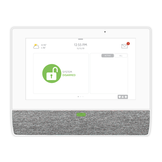
USER INTERFACE HOME SCREEN OVERVIEW The home screen is divided into three sections. The header shows the date & time, today’ s weather (Wi-Fi enrollment only), message center and the Settings tray. The Primary interface shows arming options and sensor status & partition select. -
Page 14: Message Center
USER INTERFACE MESSAGE CENTER The header contains the the pull down settings tray, the weather icon (Wi-Fi enrollment only), time/date and a message icon in the upper right portion of the screen where you will find Security Provider messages and contact info, alerts, video tutorials and FAQ’... - Page 15 USER INTERFACE SETTINGS TRAY FIND IT To access the Settings tray swipe down on the bar at the top of the screen. The Settings tray has quick access to system, battery, PowerG signal strength & Wi-Fi status Swipe down for access as well as volume control, brightness and other quick settings.
- Page 16 PROGRAMMING...
- Page 17 PROGRAMMING SETTINGS FIND IT The Settings page allows quick access to various simple features & settings. Swipe down for access SETTINGS Setting Description ENTER CODE (1111, 2222) Display Adjust brightness, font size & 12/24 hour time About Displays software, battery, Wi-Fi, Panel and PowerG information Restores remote to factory settings and erases all content.
- Page 18 CUSTOMIZATION CONNECTING TO WI-FI FIND IT To connect to a Wi-Fi network, follow Swipe down for access the steps below: Swipe down from the top menu bar SETTINGS and select settings. ENTER CODE (1111, 2222) Touch Settings (Installer Code) WI-FI Then touch “Wi-Fi”...
- Page 19 CUSTOMIZATION WEATHER FIND IT Note: This feature is only available during Wi-Fi enrollment. TODAY’S FORECAST Today’ s forecast is displayed on the weather icon with a graphical representation of precipitation and High and Low temps. 4-DAY FORECAST Touch the weather icon to get a Touch the weather icon in the 4-day forecast.
-
Page 20: Photo Frame
CUSTOMIZATION PHOTO FRAME FIND IT PHOTO FRAME The IQ Remote PowerG can be set to display digital photos when not in use. Swipe down This feature, called “Photo Frame”, can be changed or turned off through for access “Photo Frame Settings”. (Swipe down from the menu bar) PHOTO FRAME Display type... - Page 21 CUSTOMIZATION PHOTO FRAME APP BUTTONS FIND IT PLAY: Starts Photo Frame immediately. Good for testing photo frame Swipe down for access feature appearance and transitions REMOVE PHOTOS: Allows you to remove photos one by one or all at PHOTO FRAME once SETTINGS: Change the Photo Frame’...
- Page 22 CUSTOMIZATION PHOTO FRAME SETTINGS FIND IT Item Default Description Swipe down for access How long each image will show before transitioning to the next image in Duration 1 minute the library (1, 2, or 5 minutes) Effect Dissolve Transition effect used between each image (fade to black, dissolve) Shuffle Enabled Display pictures in random or sequential order...
-
Page 23: Maintenance
MAINTENANCE... -
Page 24: Upgrade Software
MAINTENANCE UPGRADE SOFTWARE FIND IT Upgrade Software Upgrade the software version using PowerG. Swipe down for access To perform a software update, follow the steps below: 1. From the drop down menu select “Settings” and enter access code (Installer/Dealer Code). SETTINGS 2. -
Page 25: Battery Replacement
MAINTENANCE BATTERY REPLACEMENT 1. Power down panel: Press and hold the power button on the side of the IQ Remote PowerG for 2 seconds and select "Power Down" from the pop up 2. Remove Battery Door: Remove the panel from the backplate or table stand and then use a small screwdriver to remove the plastic door covering the battery. -
Page 26: Troubleshooting
TROUBLESHOOTING... - Page 27 TROUBLESHOOTING ABOUT FIND IT Swipe down for access SETTINGS ENTER CODE (1111, 2222) ABOUT QOLSYS CONFIDENTIAL AND PROPRIETARY PAGE...
- Page 28 TROUBLESHOOTING ABOUT Item Description Battery Battery Status: Disconnected, Charging, Full Battery Level: Displayed in % Software Version: Current Software Version LInux Version: Software Build Number: Android Version: Panel MAC Address: Panel Up Time: Radio Software Version Device Radio Frequency PowerG* Device Network Status Sensor ID Connection: Connected/Disconnected...
-
Page 29: Power Down
TROUBLESHOOTING POWER DOWN DO NOT remove all power without following the steps below. In the event of needing to move the panel from one location to another it is safe to unplug the power supply while leaving the battery plugged in. 1. - Page 30 TROUBLESHOOTING PANEL REBOOT If the panel is experiencing difficulties you can often resolve it by resetting the operating system: 1. Press and hold the power button for 2 seconds until a pop up message appears on the screen. 2. Select “Power Reboot”. 3.
- Page 31 LEGAL...
- Page 32 LEGAL UL/cUL RESIDENTIAL FIRE & BURGLARY INSTALLATIONS This product has been tested and found in compliance with the following standards: UL1023 Household Burglar-Alarm System Units, UL985 Household Fire Warning System Units, ULC-S545 Residential Fire Warning Systems Control Units and ULC-S304 Security Level I Control Units, Accessories and Receiving Equipment for Intrusion Alarm Systems. For ULC Installations refer to the Standard for the Installation of Residential Fire Warning Systems, CAN/ULC-S540: - Use only the compatible power supply referenced in this Installation Manual.
- Page 33 LEGAL UL/ULC COMMERCIAL BURGLARY INSTALLATIONS This product has been tested and found in compliance with the following standards: UL2610 Central Station Burglar-Alarm Units and ULC-S304 Control Units, Accessories and Receiving Equipment for Intrusion Alarm Systems, Security Levels I-II. The subscriber control unit shall provide for the connection of protective wiring, conductors, and attachments in accordance with the Standard for Installation and Classification of Burglar and Holdup Alarm Systems, UL 681 in USA and in accordance with ULC-S301, CSA C22.1, Canadian Electrical Code, Part I, Safety Standard for Electrical Installations and ULC-S302 Standard for the Installation, Inspection and Testing of Intrusion Alarm Systems, in Canada.
- Page 34 LEGAL UL/ULC COMMERCIAL BURGLARY INSTALLATIONS continued… UL2610 Central Station with Standard or Encrypted Line Security Service and ULC-S304 Security Level I-II/A3 Active communication channel: - The installation must use the integral cellular communicator, which sends events over Cellular Data Network to the compatible Sur-Gard System I/II/III/IV/5 receiver.
- Page 35 LEGAL UL/ULC COMMERCIAL BURGLARY INSTALLATIONS continued… Protection of the Control Unit: The local control unit and the local power supply must be protected in one of the following ways: - The control unit and audible alarm device must be in a protected area which is armed 24 hours a day. - Each partition must arm the area protecting the control unit and the audible alarm device power supply.
- Page 36 LEGAL UL/ULC COMMERCIAL BURGLARY INSTALLATIONS continued… User Information: - The installer should advise the user and note in the User’ s Manual - Service organization name and telephone number - The programmed exit and entry time - Instructions to test system weekly - Note that the installer code cannot arm or disarm the system - The installer should caution the user not to give system information (e.g., codes, bypass methods, etc.) to casual users (e.g., service people) and to only give out codes set to expire within 24 hours...
- Page 37 LEGAL FCC & ISED CANADA COMPLIANCE STATEMENT This Class [B] digital apparatus meets all requirements of the Canadian Interference-Causing Equipment Regulations. Cet appareil numérique de la classe [B] respecte toutes les exigences du Réglement sur le matériel brouilleur du Canada. IMPORTANT! Changes or modifications not expressly approved by Qolsys Inc.
- Page 38 LEGAL FCC & ISED CANADA COMPLIANCE STATEMENT continued… This equipment has been tested and found to comply with the limits for a Class B digital device, pursuant to part 15 of the FCC Rules. These limits are designed to provide reasonable protection against harmful interference in a residential installation.
-
Page 39: Specifications
SPECIFICATIONS... - Page 40 SPECIFICATIONS Items Parameters IQ Remote PowerG Platform Android OS Android 7.1 LCD Display Size 7” LCD Resolution 1024 x 600 24bit Touchscreen Type Capacitive glass multi-touch User Codes Up to 242 Role based (Dealer, Installer, Master, User, Guest, Duress) Wireless Security R/F PowerG 912- 915MHz.
- Page 41 SPECIFICATIONS Items Parameters IQ Remote PowerG LED Indicator Status LED Disabled Speaker Mono 1W Microphone Microphone x 2 microphone Siren SPL minimum 85dB for UL985 Tamper Tamper Switch Wall and Enclosure Tamper Battery Type Lithium Polymer 2600mAh. Guangzhou Great Power Energy & Technology CO LTD. Model ICR 18650 Buttons Standby Right side button used for sleep/wake, and clean screen cancel, panel power down, panel reboot...
- Page 42 Document#: IQRPG-IM-07-22 Qolsys Inc. proprietary. Revision Date: 07/29/22 Reproduction without permission is not permitted.
Need help?
Do you have a question about the Qolsys IQ Remote PowerG and is the answer not in the manual?
Questions and answers