Advertisement
Quick Links
Advertisement
Troubleshooting

Related Manuals for Johnson Controls Tyco iotega WS910


Summary of Contents for Johnson Controls Tyco iotega WS910
- Page 1 iotega Wireless Security and Automation System V1.2 Reference Manual Models: WS910/ WS912 WARNING: This manual contains information on limitations regarding product use and function and information on the lim- itations as to liability of the manufacturer. The entire manual should be carefully read.
-
Page 2: Table Of Contents
Table of Contents Section 1: Introduction 1.1 About the System 1.2 Compatible Devices List 1.3 Specifications Section 2: Installation 2.1 Alarm Controller Installation 2.2 Controls and Indicators 2.3 Enrolling Wireless PowerG Security Devices Section 3: Operation 3.1 Using the Integrated Keypad 3.1.1 Key Functions 3.1.2 Emergency Keys 3.1.3 WPS Mode ([*][8]) - Page 3 5.2 Viewing Troubles from the Integrated Keypad 5.3 Network Troubleshooting Appendix 1: Guidelines for Locating Smoke Detectors and CO Detectors Appendix 2: Reporting Codes Appendix 3: Regulatory Information Appendix 4: SIA False Alarm Reduction Installations: Quick Reference - 3 -...
- Page 4 iotega Wireless Security and Automation System hazards and to take appropriate actions to reduce the risks of Safety Instructions for Skilled Persons injury to themselves and others). It must be installed and used within an environment that provides the pollution degree max 2, Warning: Save these instructions for future reference.
-
Page 5: Section 1: Introduction
Section 1: Introduction Section 1: Introduction 1.1 About the System The iotega is an easy to use, wireless security and home automation panel. iotega supports a range of wireless devices via PowerG or Z-Wave. Installers set up and configure the panel through a smartphone app or cloud-based portal. End users also interact with the iotega using an intuitive smartphone app, web portal or optional wirefree and touchscreen keypads. - Page 6 Section 1: Introduction Product Type Model Wireless repeater PGx920 IP Devices Camera Wi-Fi IP Camera See the Smarttech portal for available models Touchpad Wi-Fi Touchscreen (dedicated as a system keypad) WS9TCHW Phone Cellular Phone w/Wi-Fi iOS/Android based Z-Wave Devices See the portal for a complete list of supported Z-Wave devices. Central Monitoring Station Receivers Receiver Sur-Gard System I-IP Receiver...
-
Page 7: Specifications
Section 1: Introduction 1.3 Specifications Zone Configuration 128 wireless zones 19 zone types and 4 programmable zone attributes 4 touchscreen keypads supported 4 wirefree keypads 16 wireless sirens 32 wireless keys supported 8 wireless repeaters. Note that more than one wireless repeater shall be installed in a given fire alarm signaling sys- tem to provide a redundant RF transmission path. - Page 8 Section 1: Introduction Temperature range: -10°C to 55°C (50°F-131°F) Relative humidity: <93% non condensing Alarm Transmitter Equipment (ATE) Specification Communications over cellular or Ethernet Supports SIA and Contact ID Complies with TS203 021-1, -2, -3 Telecom equipment requirements Compliant with EN50136-1-1, EN50136-2, EN50131-10 Grade 2, SP2, DP2 requirements System Supervision Features The iotega continuously monitors a number of possible trouble conditions and provides audible and visual indication at the keypad if a trouble is present.
-
Page 9: Section 2: Installation
Section 2: Installation Section 2: Installation 2.1 Alarm Controller Installation A typical installation includes the following steps: 1. Set up the customer account using the SmartTech Dealer portal 2. Connect the panel 3. Enroll sensors and other devices 4. Connect to WiFi router (optional) 5. - Page 10 Section 2: Installation Create a Master Contact: 1. Select “Contacts” in the left side bar. 2. From the “Contacts” page, select “Add Contact” and complete the form. All fields marked with an asterisk (*) are required. 3. Assign a unique username and passcode for the customer to access both the end-user website and mobile applic- ation.
-
Page 11: Battery Replacement
Section 2: Installation Enroll Sensors and Devices To Enroll Sensors (Zones) and Peripheral Devices: 1. On the “Panel Settings” page, select “Add Device”. Devices can be enrolled in two ways, either through Auto Enrollment or by entering the serial number of the device into the “Add Device by Serial Number”... -
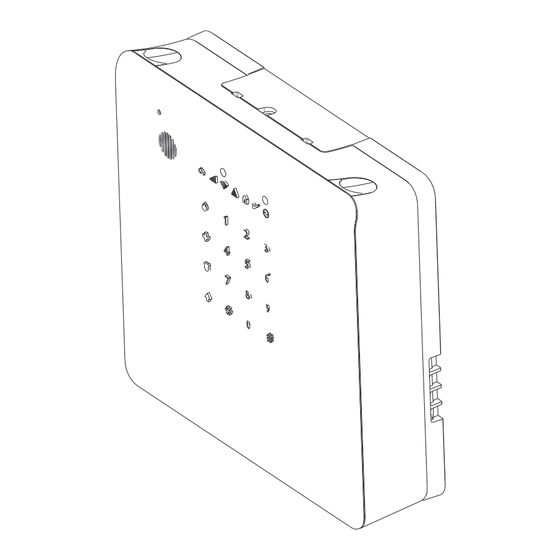
Page 12: Controls And Indicators
Section 2: Installation 1. Detach the iotega from the mounting plate by inserting a flat blade screwdriver into the slots on top of the plate and gently prying. Disconnect the AC and Ethernet cables from the iotega. 2. Remove the access cover from the back of the panel. 3. - Page 13 Section 2: Installation Indicator Description Power ON Steady AC power is connected to the system [Green] - System is not powered On - NO AC connected, and system is operating on backup battery - NO AC connected and backup battery is discharged Flashing System test in progress ( Ready, Trouble and Arm LED’s flashing at same time) Ready...
-
Page 14: Enrolling Wireless Powerg Security Devices
Section 2: Installation Indicator Description Cellular Sig- ON Steady [Green] Strong signal connection nal Strength ON Steady Weak signal connection [Amber] ON Steady No Signal or no connection [Red] Flashing System Test ( AC, Ready, Trouble, Arm LED’s, WiFi Trouble, Cellular Trouble & System remote status flashing at same time) [Amber] Remote Con-... - Page 15 Section 2: Installation 4. Submit the settings to finish enrollment. 5. Continue the above process until all devices are enrolled. To manually enroll: 1. Enable manual enrollment using the installer portal or app 2. Add the device zone type, partition, name, and electronic serial number (ESN). 3.
-
Page 16: Section 3: Operation
Section 3: Operation Section 3: Operation This section describes how to use the iotega‘s integrated keypad. 3.1 Using the Integrated Keypad The iotega includes a built-in, touch sensitive keypad that activates by proximity. From the keypad, users can arm and dis- arm the system, view system troubles, and activate the Fire (F), Auxiliary (A) and Panic (P) keys. -
Page 17: Wps Mode ([*][8])
Section 3: Operation Panic Keypad beeps three times and a signal is sent to the monitoring station. Panic alarm Can be configured as audible or silent To use the Emergency keys: 1. Press the Shift key (↑). The Emergency keys are illuminated (if enabled ). If an Emergency key is not pressed within 10 seconds, the keypad returns to normal operating mode. -
Page 18: Quick Arming
Section 3: Operation Stay Arming is intended to arm the perimeter of the premises while permitting movement within. The Ready light must be on to arm the system. If the Ready light is off, ensure all protected doors and windows are secure or bypassed. To Stay arm the system, enter a valid user code and stay within the premises (do NOT violate a zone programmed as Delay). -
Page 19: Section 4: Programming Options
Section 4: Programming Options Panic Button Section 4: Programming This function is used to enable or disable the Panic [P] but- ton on the integrated keypad. When enabled, pressing and Options holding the [P] button for 2 seconds sends an emergency This section provides descriptions of all alarm controller alarm reporting code to the central monitoring station. -
Page 20: System Configuration Options
Section 4: Programming Options Ready LED Flashes for Force Arm Contact ID When this option is enabled, the keypad Ready LED flashes Each of the digits indicate specific information about the sig- to indicate that a force arm zone is open but the system is nal. - Page 21 Section 4: Programming Options Trouble Beeps (Audible/ Auto-silent) Note: Bypassed wireless zones do not generate an audible zone. When this option is enabled, trouble beeps are not sounded for any trouble condition except Fire/CO. For these, trouble OFF: Wireless zone faults do not sound the siren. beeps sound every 10 seconds for the duration of the Defaul- Disabled...
- Page 22 Section 4: Programming Options When disabled, any burglary alarm requires remote reset When this option is disabled, open zones do not prevent after disarming the partition. arming. Default: Disabled Default: Enabled Valid range: Enabled/Disabled Valid range: Enabled/Disabled EU Entry Procedure Engineer’s Reset (EU) When this option is enabled, if an alarm occurs on a zone When this option is enabled, if the system has gone into...
-
Page 23: Automatic Bypass
Section 4: Programming Options Access Code is Required to View Alarms In Memory 003 Sequential Detection The Burglary Verification Timer operates in minutes. The first alarm in the sequence When this option is enabled, an access code must be causes an audible bell. entered to view alarms in memory. - Page 24 Section 4: Programming Options Gateway IP Address Wireless Supervisory Window This is the resolved value based on the DHCP address Use this option to program the time window for reception of assignment. supervision (keep alive) signals from wireless devices enrolled on the system. If a device does not report at least Default: 000.000.000.000 once within the programmed time window, a hardware fault...
-
Page 25: Reporting Configuration Options
Section 4: Programming Options message is briefly displayed on the keypad when the delay Default: Enabled is canceled. Valid range: Enabled, Disabled Default: 000 (Standard) Valid range: 000-255 Seconds (Standard) New Alarms Disconnect 2-Way Audio When this option is enabled, a listen in/2-way audio session AC Failure Communication Delay in progress is disconnected in favor of the incoming alarm. -
Page 26: Network Configuration Options
Section 4: Programming Options Local keypad Lockout Alarm Restoral Remote Lockout When this option is enabled, the following alarm restoral Default: Enabled events are reported to the central monitoring station when they occur. When disabled, alarm restoral events are not Valid range: Enabled/Disabled reported. - Page 27 Section 4: Programming Options LAN/WAN IP Address WLAN Client Control This section is used to program a static IP address. To use a This option is used to control WiFi client mode. static IP address, the option LAN/WLAN Obtain IP Address Default: Enabled must be set to Static IP address.
-
Page 28: User Configuration Options
Section 4: Programming Options Update WiFi SSID and password 4.2.4 User Configuration Options Create new users Program a duress code This section describes programming options for configuring Program user labels system users. Supervisor users can only add, edit or delete users assigned to the same partitions as they are. -
Page 29: Central Monitoring Station Programming Options
Section 4: Programming Options Note: Powering cycling the panel opens the installer access CMS Ethernet 1 DNIS window. The Dialed Number Information Service (DNIS) is used in addition to the account code to identify the communicator When this option is disabled, the installer does not require a module at the central monitoring station. - Page 30 Section 4: Programming Options Note: If both Ethernet Receiver 2 and Cellular Receiver 1 CMS Ethernet 2 Remote Port are the same receiver (IP and port number are identical), Eth- This section is used to program the port number used by Eth- ernet Receiver 2 account will be used for Ethernet and Cel- ernet 1.
-
Page 31: Other Communicator Related Options
Section 4: Programming Options is available from the network carrier. CMS Cellular 2 APN The APN determines the cellular network that the com- Note: When a SIM card with a custom APN is used, the unit municator will connect to. This information is available from will not have access to the Internet. -
Page 32: Partition Configuration Options
Section 4: Programming Options Note: Programming an interval of less than 5 minutes or a CMS Event Heartbeat Interval value greater than 999999 disables the test transmission. This option is used to program the periodic heartbeat inter- val between the alarm panel and the cellular communicator. The heartbeat is used to monitor for image/audio file Cellular Test Transmission Time requests. - Page 33 Section 4: Programming Options Partition Label Default: Disabled This option is used to add a unique label to each partition on Valid range: Enabled/Disabled the system. This label is displayed on partition keypads and event messages. Quick Exit Default: Blank When this option is enabled, users can temporarily bypass a Valid range: 32 character ASCII...
-
Page 34: Wireless Device Configuration Options
Section 4: Programming Options Auto Arm Postpone Timer (for schedule only) Keypad Label This option is used to program a time delay before the Auto This section is used to program a user-friendly name for the Arm sequence begins. Programming 0 cancels auto arming. keypad. -
Page 35: Wireless Siren Configuration Options
Section 4: Programming Options Armed LED Power Save Option 4.6.2 Wireless Siren Configuration This option is used to control the Armed LED on/off state. If Options enabled, the Armed LED does not illuminate when the sys- tem is armed to conserve battery life. The following section provides descriptions of all wireless Default: Disabled... -
Page 36: Wireless Key Configuration Options
Section 4: Programming Options Activity LED Wireless Key Button Programming When this option is enabled, the Activity LED flashes every This option is used to program functionality for all available few seconds to indicate that the siren is enrolled and active. buttons on the wireless key. -
Page 37: Wireless Glassbreak Configuration Options
Section 4: Programming Options Chime Tone 4.6.5 Wireless Glassbreak Con- This option is used to select the tone emitted by the device figuration Options when the zone is tripped. Default: Beeps The following sections are used for programming glass- Valid range: Beeps, Bing Bing, Ding Dong, Alarm Tone break detectors. -
Page 38: Wireless Temperature Configuration Options
Section 4: Programming Options Swinger Shutdown Enabled (read-only) Door Chime Disabled Two Way Audio Enabled (read-only) Alarm Report Enabled Talk Listen Enabled (read-only) Burglary Verified Disabled Transmission Delay Disabled Bell Audible Enabled (read-only) Supervision Bell Steady Enabled (read-only) This section is used to enable/disable wireless supervision Bypass Enable Enabled (read-only) of the device. -
Page 39: Wireless Flood Configurations
Section 4: Programming Options Low Temperature Alarm Bell Steady Disabled (read-only) This option is used to set the temperature threshold for activ- Bypass Enable Disabled (read-only) ating the Low Temperature alarm. Force Arm Disabled (read-only) This option is disabled by entering -999 or 999. Swinger Shutdown Disabled (read-only) Default:... -
Page 40: Wireless Pir (No Cam) Configurations
Section 4: Programming Options Zone Attribute Default: This section is used to customize zone behavior for the Valid range: -3, -2, -1, 0, 1, 2, 3 device. The table below specifies the status of each attribute for this device. Image Contrast See "Available Zone Attributes"... -
Page 41: Wireless Door Window Configurations
Section 4: Programming Options Chime Tone Default: Enabled This option is used to select the tone emitted by the device Valid range: Enabled/Disabled when the zone is tripped. Default: Beeps High Traffic Shutdown Valid range: Beeps, Bing Bing, Ding Dong, Alarm Tone Activating this feature helps conserve battery power when the system is disarmed by configuring a reporting timer. -
Page 42: Wireless Shock Sensor Configurations
Section 4: Programming Options Zone EOL Configuration Default: Enabled This option is used to configure end of line resistors for the Valid range: external input terminals. The alarm panel uses EOL resistors to monitor for fault or alarm conditions. Chime Tone Default: EOL Disable This option is used to select the tone emitted by the device... -
Page 43: Repeater Configuration Options
Section 4: Programming Options Shock Sensitivity Level Transmission Delay Disabled This option is used to adjust the sensitivity of the sensor. The Bell Audible Enabled (read-only) lower the number, the more sensitive the device. Use the Bell Steady Enabled (read-only) lowest settings for hard surfaces such as concrete. -
Page 44: Available Zone Types
4.8 Available Zone Types Delay 1 Commonly assigned to primary points of entry. Follows entry delay 1 and exit delay timers. Arming the alarm system starts the exit delay timer. After the exit delay has expired, opening the door starts the entry delay timer. During entry delay, the keypad buzzer prompts the user to disarm the system. -
Page 45: Available Zone Attributes
24-Hour This zone is active and reports alarms at all times when tripped. The siren and keypad buzzer do not activate. Supervisory 24-Hour This zone type is used with temperature sensors and is activated when the temperature rises above a programmed threshold. Instant alarm when Temperature activated, audible alarm at default. -
Page 46: System Control
Note: The checksum digit is omitted on 19-digit SIM card numbers. Cellular Device Type This section displays the type of cellular module used by the system. E.g., UE910-N3G, LE910-SVG Cellular Signal Strength This section displays the strength of the cellular signal: Strong, Weak, None. Radio Network Technology This section displays the mobile wireless telecommunications technology used by the cellular radio. -
Page 47: Network
4.11.1 Network Test Transmission Ethernet and Cellular test transmissions check to see if the selected communication path between the iotega and the cent- ral monitoring station is functioning correctly. Both Ethernet/Cellular 1 (primary receiver) and Ethernet/Cellular 2 (secondary receiver) can be tested separately based on individual reporting configurations. -
Page 48: Section 5: Troubleshooting
Section 5: Troubleshooting Section 5: Troubleshooting 5.1 Testing Power up the system Program options as required (see programming section) Trip then restore zones Verify correct reporting codes are sent to the central monitoring station 5.2 Viewing Troubles from the Integrated Keypad 1. - Page 49 Section 5: Troubleshooting Fire/CO Trouble 1-128 RF Delinquency 1-128 Siren Future Use 1-16 Battery Trouble 1-16 Tamper 1-16 Fault (Supervision) 1-16 Not Networked 1-16 RF Delinquency 1-16 Keypad Battery Trouble Tamper Fault (Supervision) Not Networked RF Delinquency Repeater Battery Trouble Tamper Fault (Supervision) Not Networked...
-
Page 50: Network Troubleshooting
Section 5: Troubleshooting 5.3 Network Troubleshooting Network Con- Connection Requirements Comments figuration DHCP (default None Since the iotega can receive IP from the network and the network is not blocking any ports, DHCP router settings) must include the following items •... - Page 51 Appendix 1: Guidelines for Locating Smoke Detectors and CO Detectors Appendix 1: Guidelines for Locating Smoke Detectors and CO Detectors The following information is for general guidance only and it is recommended that local fire codes and regulations be con- sulted when locating and installing smoke and CO alarms.
-
Page 52: Carbon Monoxide Detectors
Appendix 1: Guidelines for Locating Smoke Detectors and CO Detectors Figure 3a Figure 4 Carbon Monoxide Detectors Carbon monoxide is colorless, odorless, tasteless, and very toxic. It also moves freely in the air. CO detectors can measure the concentration and sound a loud alarm before a potentially harmful level is reached. The human body is most vulnerable to the effects of CO gas during sleeping hours;... - Page 53 Appendix 1: Guidelines for Locating Smoke Detectors and CO Detectors Make sure that all border doors and windows are easily opened. Ensure that they are not painted shut, and that their locking mechanisms operate smoothly. If opening or using the exit is too difficult for children, the elderly or handicapped, plans for rescue should be developed.
- Page 54 Appendix 2: Reporting Codes Appendix 2: Reporting Codes The following tables contain Contact ID and Automatic SIA format reporting codes. Contact ID Each of the digits indicate specific information about the signal. For example, if zone 1 is an entry/exit point, the event code contains [34].
- Page 55 Appendix 2: Reporting Codes Section # Definition Dialer Dir- Automatic Contact ID SIA Auto Rep Codes** ection* Codes Repeater 7 tamper/restore alarm E(3)83-907 / R (3)83-907 TA-0907 / TR-0907 Repeater 8 tamper/restore alarm E(3)83-908 / R (3)83-908 TA-0908 / TR-0908 Keypad Lockout - Incorrect access code entry E(4)61-000 / R(4)61-000 JA-0000...
- Page 56 Appendix 2: Reporting Codes Section # Definition Dialer Dir- Automatic Contact ID SIA Auto Rep Codes** ection* Codes Wireless Device Low Battery trouble/restore. MA/R E(3) 84-ZZZ XT-ZZZZ / XR-ZZZZ R(3) 84-ZZZ Wireless Zone AC trouble/restore MA/R E(3)A1-ZZZ AT-ZZZZ / AR-ZZZZ R(3)A1-ZZZ Wireless Device fault/restore MA/R...
- Page 57 Appendix 2: Reporting Codes Section # Definition Dialer Dir- Automatic Contact ID SIA Auto Rep Codes** ection* Codes Miscellaneous Alarms Duress Alarm - Code entered at keypad E(1)21-000 HA-0000/ HH-0000 Opening After Alarm - Disarmed with alarm in memory E(4)58-000 OR-0000 Recent Closing - Alarm occurs within two minutes of system E(4)59-UUU...
- Page 58 Appendix 2: Reporting Codes Zone Definition SIA Auto Rep Codes Contact ID Auto Rep Codes Delay 1 BA-ZZZZ / BH-ZZZZ E(1) 3A - ZZZ / R(1)3A- ZZZ Delay 2 BA-ZZZZ / BH-ZZZZ E(1) 3A - ZZZ / R(1)3A- ZZZ Instant BA-ZZZZ / BH-ZZZZ E(1) 3A - ZZZ / R(1)3A- ZZZ Interior...
- Page 59 Appendix 3: Regulatory Information Appendix 3: Regulatory Information This product has been tested and found in compliance with the following standards: UL1023 Household Burglar-Alarm System Units UL985 Household Fire Warning System Units ULC-S545-02 Residential Fire Warning System Control Units ORD-C1023-1974 Household Burglar-Alarm System Units This product has also been tested and found in compliance with the ANSI/SIA CP-01-2014 Control Panel Standard –...
- Page 60 Appendix 3: Regulatory Information The following models are covered by this guide: WS900-19, WS900-29, 3G7090, LT7090 (used in North America only), WS901-14, WS901-24EU, WS901-18, WS901-28, WS912-18, WS912-28, and 3G7090-EU. The full text of the EU declarations of conformity for the models mentioned below are available at the following internet addresses: Model WS901-14: http://dsc.com/pdf/1707001 Model WS901-24EU: http://dsc.com/pdf/1707002...
- Page 61 Appendix 4: SIA False Alarm Reduction Installations: Quick Reference Appendix 4: SIA False Alarm Reduction Installations: Quick Reference Caution Fire Alarm Verification feature (Auto Verified Fire Zone) is supported on the DSC Wireless Smoke Detector, Model PGx916 and PGx926. The fire alarm delay is 40s. Notes: Programming at installation may be subordinate to other UL requirements for the intended application.
- Page 62 Appendix 4: SIA False Alarm Reduction Installations: Quick Reference SIA Feature Comments Range/Default Requirement Programming Section Cancel Annunciation Access to the reporting code for Alarm Annunciate that a Cancel Required Canceled was transmitted. Default: Panel Settings>Panel Con- Enabled figuration>System Configuration> >...
-
Page 63: Limited Warranty
Digital Security Controls recommends that the entire system be completely tested on a regular Limited Warranty basis. However, despite frequent testing, and due to, but not limited to, criminal tampering or elec- trical disruption, it is possible for this product to fail to perform as expected. Digital Security Controls warrants the original purchaser that for a period of twelve months from Out of Warranty Repairs the date of purchase, the product shall be free of defects in materials and workmanship under nor-... - Page 64 Some of these heat sources could be heaters, radiators, stoves, barbecues, fireplaces, sunlight, WARNING: Installer please read carefully steam vents, lighting and so on. Power Failure Note to Installers Control units, intrusion detectors, smoke detectors and many other security devices require an The warnings on this page contain vital information.
- Page 65 EULA grants You no rights to use such content. All rights not expressly granted under this EULA EULA are reserved by DSC and its suppliers. EXPORT RESTRICTIONS - You agree that You will not export or re-export the SOFTWARE IMPORTANT - READ CAREFULLY: DSC Software purchased with or without Products and PRODUCT to any country, person, or entity subject to Canadian export restrictions.
- Page 66 The trademarks, logos, and service marks displayed on this document are registered in the United States [or other countries]. Any misuse of the trademarks is strictly prohibited and Tyco will aggressively enforce its intellectual property rights to the fullest extent of the law, including pursuit of criminal prosecution wherever necessary.
Need help?
Do you have a question about the Tyco iotega WS910 and is the answer not in the manual?
Questions and answers