Table of Contents
Advertisement
Quick Links
Advertisement
Table of Contents

Subscribe to Our Youtube Channel
Related Manuals for Webasto PosiCharge ProCore Series


Summary of Contents for Webasto PosiCharge ProCore Series
- Page 1 PosiCharge ProCore™ Installation Manual 24407-W-76_02...
- Page 2 Disclaimer: this manual includes the latest information available at the time of printing. Webasto Charging Systems, Inc.. Reserves the right to make changes to this manual and/ or product without further notice. Changes or modifications to this product not com- pleted by an authorized service provider could void the product warranty.
- Page 3 To ensure superior service, please write down the unit’s serial number in the owner’s record above and have it available when contacting Webasto customer support. The serial number can be found on the nameplate rating label on the left side of the unit.
-
Page 4: Table Of Contents
SAVE THESE INSTRUCTIONS! This manual contains important instructions for the installation of the PosiCharge ProCore charger series. CONTENTS 1 INTRODUCTION ................1 1.1 Symbol Usage .................2 1.2 General Safety Precautions .............3 2 SYSTEM DESCRIPTION AND INSTALLATION PROCEDURE ....5 About This Chapter ..............6 Introduction ................6 Performance Ratings ..............7 Site Preparation ..............8... -
Page 5: Introduction
CH A P T ER 1 INTRODUCTION... -
Page 6: Symbol Usage
1.1 SYMBOL USAGE The PosiCharge ProCore is designed with safety as the highest priority. Installation must comply with all local codes and the following safety precautions must be read and observed. Indicates information about safety practices which, if not followed, may result in serious injury or death. Indicates information about safety practices which, if not followed, could result in personal injury, fire, or equipment overheating. -
Page 7: General Safety Precautions
1.2 GENERAL SAFETY PRECAUTIONS BEFORE YOU BEGIN • Read this entire manual and cautionary markings on the PosiCharge™ ProCore cabinet. • Make sure you also read the IMPORTANT SAFETY INSTRUCTIONS below. • Installing or servicing this charger must be done by qualified personnel ONLY. - Page 8 Follow the National Electrical Code (NEC) and local codes. NEC and local codes take precedence. If any instructions in this manual conflict with NEC or local codes, contact Webasto Inc. for further information. CONTACT POSICHARGE’S CUSTOMER SERVICE DEPARTMENT PRIOR TO PERFORMING ANY SERVICE ON THE UNIT.
-
Page 9: System Description And Installation Procedure
C H A P T ER 2 SYSTEM DESCRIPTION AND INSTALLATION PROCEDURE... -
Page 10: About This Chapter
Identifier Module (BMID), precise charging control, electrolyte temperature monitoring, “easy-service” power stage modules, and a dynamic equalization scheduler. ProCore models are based on Webasto’s robust, single-port architecture for maximum flexibility and modularity. The ProCore product line features a proven MOSFET technology, a broad power range, multi-voltage flexibility, and value-added options that can support most material handling and fork truck batteries. -
Page 11: Performance Ratings
The PosiCharge ProCore series is compatible with: • Smart Battery Monitor and Identification Device (BMID) • Electrolyte Immersed Thermistor • Auto watering • Stack lights • CAN Interface • PosiNet data reporting systems Safety Compliance: • CE, UL1564, CSA, RCM •... -
Page 12: Site Preparation
2.4 SITE PREPARATION Refer to the Important Safety Instructions above regarding the environmental considerations for the charging room where you are installing the charger. Figure 1: Mounting Template indicates the locations for the four mounting screws/bolts, where the horizontal distance is 18” on centers and the vertical distance is 29½” on centers. - Page 13 2.4.1 WALL MOUNT The chargers are designed for wall mounting. Refer to Table 1 above for your charger’s weight to determine the correct mounting hardware. The cabinets are built according to the number of charger modules required by your facility. Figure 2: Single and Triple Chargersbelow shows for a single module and multiple modules.
-
Page 14: Unpacking The Product
Figure 4: Rack Mount Figure 4 above shows a rack mount, also using Unistruts. Do NOT mount to walls with steel studs and drywall covering if the steel studs are not structurally rated. In Figures 3 and 4 above, the object next to the cabinet (called a “Pogo Stick”) is a spring-loaded cable support and retractor that keeps the cables off the floor. -
Page 15: Input Wiring
2.6 INPUT WIRING The input wiring is a 3-wire delta configuration, no neutral, and a ground wire. The cabinet has a 1⅛ ” diameter to accept a ¾” conduit. See Figure 5: Wiring Panel. Figure 5: Wiring Panel Cabinet has a knock-out of 1⅛” diameter fitting on the bottom left of the cabinet (next to the output cables) to accommodate ¾”... -
Page 16: Installation
2.7 INSTALLATION This section discusses the installation procedures for wall-mounted and pedestal- mounted cabinets and charger modules, as well as pogo stick cable mounts and stack lights. 2.7.1 WALL MOUNT Based on the planning you performed in Section 2.4, you are now ready to begin installation. - Page 17 Figure 7: Pedestal Mount 2.7.3 POGO STICK WALL MOUNT An optional kit allows pogo stick cable hangers to be mounted next to a charger. Refer to Figure 8 below. 1. From the kit, select the right angle mounting bracket, the spring clamping nut, the washers and the machine screw.
- Page 18 3. Use the crimp terminals (P/N# 05358) to splice the RED, YELLOW, VIOLET and BLACK wires to the stack light lead wires, as shown in Figure 11. 4. Insulate unused wires with heat shrink tubing (P/N# 02422). 5. Install four cable tie mounts (P/N# 03484) at the locations shown in Figure 10, then secure the wiring with the included cable ties.
- Page 19 Stack Light Pole Stack Light Mount Wiring Cable Tie Mounts Figure 11: Stack Light Mounting and Wiring 2.7.5 CHARGER MODULE INSTALLATION The cabinet can contain up to three charger modules. To install the charger modules, remove the cover plate from the right side of the cabinet. You may insert modules in the cabinet in any of the three positions—there are no requirements for the order or position in which they are installed.
-
Page 20: Battery Connection
2.8 BATTERY CONNECTION Connect the charger to the battery by positioning the fork truck within the charging cable length, then grasp the connector handle and firmly insert the connector into the connector socket on the fork truck. See Figure 13: Charging Cable Connector below. -
Page 21: Checklist
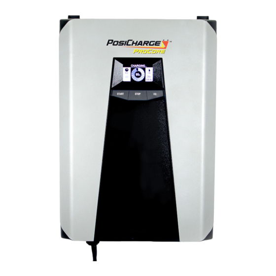
2.9 CHECKLIST Perform the following steps in order after you have completed the utility-to- charger wiring connections. At the charger: Lockout utility breaker. Confirm that utility breakers and wire gauge conform to requirements. Confirm that charger is securely attached to its supports. Confirm that utility cover plate is installed. - Page 22 Figure 15: Configuring the Charger Once the charger is programmed and set up, connected to the battery, and in operation, the final result of the battery charge is shown in Figure 16: Charge Complete. Figure 16: Charge Complete INSTALLATION COMPLETE...
- Page 24 PosiCharge™ systems, a product line of Webasto Charging Systems, Inc.. 1.866.767.4242 | posicharge.com | posichargeprocore.com | customerservice@posicharge.com © 2020 Webasto Charging Systems, Inc. 1960 Walker Avenue, Monrovia, CA 91016-4847 24407-W-76_02...
Need help?
Do you have a question about the PosiCharge ProCore Series and is the answer not in the manual?
Questions and answers