Table of Contents
Advertisement
Quick Links
Advertisement
Chapters
Table of Contents

Related Manuals for Komatsu D65EX-12


Summary of Contents for Komatsu D65EX-12
- Page 2 FOREWORD...
- Page 3 If you sell the machine, be sure to give this manual to the new owners together with the machine. Komatsu delivers machines that comply with all applicable regulations and standards of the country to which it has been shipped. If this machine has been purchased in another country or purchased from someone in another country, it may lack certain safety devices and speciffications that are necessary for use in your country.
- Page 4 FOREWORD FOREWORD...
- Page 5 FOREWORD FOREWORD...
-
Page 6: Foreword
FOREWORD SAFETY INFORMATION SAFETY INFORMATION To enable you to use this machine safely, safety precautions and labels are given in this manual and affixed to the machine to give explanations of situations involving potential hazards and of the methods of avoiding such situa- tions. - Page 7 Continuing improvements in the design of this machine can lead to changes in detail which may not be reflected in this manual. Consult Komatsu or your Komatsu distributor for the latest available information of your machine or for questions regarding information in this manual.
-
Page 8: Introduction
FOREWORD INTRODUCTION INTRODUCTION This Komatsu machine is designed to be used mainly for the following works: Dozing Smoothing Cutting into hard or frozen ground or ditching. Felling trees, removing stumps See the section "WORK POSSIBLE USING BULLDOZER (PAGE 3-86)" for further details. -
Page 9: Necessary Information
FOREWORD NECESSARY INFORMATION NECESSARY INFORMATION When requesting service or ordering replacement parts, please inform your Komatsu distributor of the following items. MACHINE SERIAL NO. PLATE AND POSITION This is at the front bottom right of the operator's seat. ENGINE SERIAL NO. PLATE AND POSITION... -
Page 10: Position Of Service Meter
FOREWORD NECESSARY INFORMATION POSITION OF SERVICE METER Monitor panel specification This is at the left upper part of the monitor panel. Gauge panel specification The gauge is located on the left lower part of the monitor panel. TABLE OF ENTER SERIAL NO. AND DISTRIBUTOR Machine serial No. -
Page 11: Table Of Contents
FOREWORD CONTENTS CONTENTS FOREWORD FOREWORD................................. 1-2 SAFETY INFORMATION............................1-5 INTRODUCTION..............................1-7 FRONT/REAR, LEFT/RIGHT DIRECTIONS OF MACHINE ............... 1-7 NECESSARY INFORMATION ..........................1-8 MACHINE SERIAL NO. PLATE AND POSITION ..................1-8 ENGINE SERIAL NO. PLATE AND POSITION ..................1-8 POSITION OF SERVICE METER ......................1-9 TABLE OF ENTER SERIAL NO. - Page 12 FOREWORD CONTENTS LAMP ................................ 3-17 CONTROL LEVERS AND PEDALS ......................3-18 FUSE ................................ 3-26 ELECTRIC POWER TAKE-OUT ADAPTER .................... 3-28 DOOR-OPEN LOCK ..........................3-29 SASH GLASS INTERMEDIATE LOCK..................... 3-29 CAP, COVER WITH LOCK........................3-30 HOT AND COOL BOX ..........................3-31 OPERATION MANUAL STORAGE ......................
- Page 13 FOREWORD CONTENTS TROUBLESHOOTING............................3-111 AFTER RUNNING OUT OF FUEL......................3-111 TOWING THE MACHINE ........................3-111 IF BATTERY IS DISCHARGED......................3-112 OTHER TROUBLE ..........................3-116 MAINTENANCE GUIDE TO MAINTENANCE ..........................4-2 OUTLINE OF SERVICE............................4-5 OUTLINE OF OIL, FUEL, COOLANT ......................4-5 RELATING TO ELECTRIC SYSTEM ......................
- Page 14 FOREWORD CONTENTS ATTACHMENTS, OPTIONS GENERAL PRECAUTIONS ..........................6-2 PRECAUTIONS RELATED TO SAFETY ....................6-2 SUSPENSION SEAT ............................6-3 HEADREST ................................6-4 HANDLING ACCUMULATOR..........................6-5 EQUIPPING THE FIRE EXTINGUISHER AND THE FIRST-AID KIT ..............6-7 INDEX ................................... 7-1 1-13...
-
Page 15: Safety
SAFETY WARNING Please be sure that you fully understand this manual and the precautions related to safety for the machine. When operat- ing or servicing the machine, always follow these precaus- tions strictly. - Page 16 SAFETY SAFETY SAFETY SAFETY LABELS..............................2-4 POSITIONS OF SAFETY PICTOGRAMS ....................... 2-4 SAFETY LABELS............................. 2-5 GENERAL PRECAUTIONS ..........................2-8 SAFETY RULES ............................2-8 IF ABNORMALITIES ARE FOUND ......................2-8 CLOTHING AND PERSONAL PROTECTIVE ITEMS ................2-8 FIRE EXTINGUISHER AND FIRST AID KIT ....................2-8 SAFETY FEATURES ..........................
- Page 17 SAFETY SAFETY PRECAUTIONS FOR OPERATION ........................2-17 STARTING ENGINE ............................2-17 CHECKS BEFORE STARTING ENGINE ....................2-17 PRECAUTIONS WHEN STARTING......................2-18 PRECAUTIONS IN COLD AREAS ......................2-18 OPERATION..............................2-19 CHECKS AFTER OPERATION ........................ 2-19 PRECAUTIONS FOR MOVING MACHINE FORWARD OR IN REVERSE ..........2-19 PRECAUTIONS WHEN TRAVELING.......................
-
Page 18: Safety Labels
If the labels are damaged, lost, or cannot be read properly, replace them with new ones. For details of the part numbers for the labels, see this manual or the actual label, and place an order with Komatsu distributor. POSITIONS OF SAFETY PICTOGRAMS... -
Page 19: Safety Labels
SAFETY SAFETY LABELS SAFETY LABELS (1) Precautions for operation, inspection and mainte- (2) Precautions when traveling in reverse nance (09651-03001) (09802-13000) (3) Precautions for leaving the operator's seat (4) Precautions for high-temperature hydraulic oil (09654-33001) (09653-03001) - Page 20 SAFETY SAFETY LABELS (5) Precautions for high-temperature cooling water (6) Precautions for handling accumulator (09668-03001) (7) Precautions for check and adjust track tension (8) Precautions for handling electric wires (09657-03003) (09808-03000) Safety label is attached on the back side of the inspection cover of the track frame.
- Page 21 COMPLY WITH THE FOLLOWING REQUIREMENTS: a) ISO 3471 (ROPS) & ISO 3449 (FOPS) b) SAE J & SAE J Altering ROPS may weaken it. Consult Komatsu Distoributor before altering. WA R N I N G ROPS may provide less protection if it has been structurally dam- aged or involved in roll-over.
-
Page 22: General Precautions
SAFETY GENERAL PRECAUTIONS GENERAL PRECAUTIONS SAFETY RULES Only trained and authorized personnel can operate and maintain the machine. Follow all safety rules, precautions and instructions when operating or performing maintenance on the machine. If you are under the influence of alcohol or medication, your ability to safely operate or repair your machine may be severly impaired putting yourself and everyone else on your jobsite in danger. -
Page 23: Safety Features
SAFETY GENERAL PRECAUTIONS SAFETY FEATURES Be sure that all guards and covers are in their proper position. Have guards and covers repaired immediately if they are damaged. Understand the method of use of safety features and use them properly. Never remove any safety features. Always keep them in good operating condition. KEEP MACHINE CLEAN If water gets into the electrical system, there is a hazard that it will cause malfunctions or misoperation. -
Page 24: Handrails And Steps
SAFETY GENERAL PRECAUTIONS When leaving the machine, always lower the work equip- ment completely to the ground, set safety lock lever (1) and brake lock lever (2) securely to the LOCK position, then stop the engine. Use the key to lock all the equipment. Always remove the key, take it with you, and keep it in the specified place. -
Page 25: Mounting And Dismounting
SAFETY GENERAL PRECAUTIONS MOUNTING AND DISMOUNTING Never jump on or off the machine. Never get on or off a moving machine. If the machine starts to move when there is no operator on the machine, do not jump on to the machine and try to stop it. -
Page 26: Prevention Of Burns
SAFETY GENERAL PRECAUTIONS PREVENTION OF BURNS Hot coolant To prevent burns from hot water or steam spurting out when checking or draining the coolant, wait for the water to cool to a temperature where it is possible to touch the radi- ator cap by hand before starting the operation. -
Page 27: Action If Fire Occurs
Komatsu distributor. If ROPS is deformed by falling objects or by rolling over, its strength lowers and its design functions cannot be maintained. In this case, be sure to ask your Komatsu distributor about repair method. 2-13... -
Page 28: Precautions For Attachments
Any modification mode without authorization from Komatsu can create hazards. Before making a modification, consult your Komatsu distributor. Komatsu will not be responsible for any injuries, accidents, or product failures resulting from modifications made without authorization from Komatsu. SAFETY AT WORKSITE Before starting operations, thoroughly check the area for any unusual conditions that could be dangerous. -
Page 29: Working On Loose Ground
SAFETY GENERAL PRECAUTIONS WORKING ON LOOSE GROUND Avoid traveling or operating your machine too close to the edge of cliffs, overhangs, and deep ditches. The ground may be weak in such areas. If the ground should collapse under the weight or vibration of the machine, there is a hazard that the machine may fall or tip over. -
Page 30: Ventilation For Enclosed Areas
Do not allow other persons to approach during the operation. Always observe the rules and regulations for the work site and environmental standards. This machine does not use asbestos, but there is a danger that imitation parts may contain asbestos, so always use genuine Komatsu parts. 2-16... -
Page 31: Precautions For Operation
SAFETY PRECAUTIONS FOR OPERATION PRECAUTIONS FOR OPERATION STARTING ENGINE If there is a warning tag hanging from the work equipment con- trol lever, do not start the engine or touch the levers. CHECKS BEFORE STARTING ENGINE Carry out the following checks before starting the engine at the beginning of the day's work. Remove all dirt from the surface of the window glass to ensure a good view. -
Page 32: Precautions When Starting
SAFETY PRECAUTIONS FOR OPERATION PRECAUTIONS WHEN STARTING When starting the engine, sound the horn as a warning. Start and operate the machine only while seated. Do not allow anyone apart from the operator to ride on the machine. Do not short circuit the starting motor circuit to start the engine. It is not only dangerous, but will also cause damage to the equipment. -
Page 33: Operation
SAFETY PRECAUTIONS FOR OPERATION OPERATION CHECKS AFTER OPERATION When carrying out the checks, move the machine to a wide area where there are no obstructions, and operate slowly. Do not allow anyone near the machine. Always fasten your seat belt. Check for any abnormality in the sound of the machine, vibration, heat, smell, or gauges;... -
Page 34: Precautions When Traveling
SAFETY PRECAUTIONS FOR OPERATION PRECAUTIONS WHEN TRAVELING When operating the machine, take care that it will not exceed its performance values such as stability, maxi- mum using load, etc. to prevent rolling of the machine caused by an overload and disasters caused by break- age of the work equipment. -
Page 35: Traveling On Slopes
SAFETY PRECAUTIONS FOR OPERATION TRAVELING ON SLOPES To prevent the machine from tipping over or slipping to the side, always do as follows. When traveling on slopes, keep the work equipment approximately 20 to 30cm (8 to 12 in) above the ground. In case of emergency, quickly lower the work equipment to the ground immediately to help stop the machine. -
Page 36: Parking Machine
SAFETY PRECAUTIONS FOR OPERATION PARKING MACHINE Park the machine on firm, level ground. Select a place where there is no hazard of falling rocks or landslides, or of flooding if the land is low. Lower the work equipment completely to the ground. When leaving the machine, set the steering, directional and gear shift levers in the N (Neutral) position and set the blade lever in the holding position, then apply safety lock... -
Page 37: Transportation
SAFETY PRECAUTIONS FOR OPERATION TRANSPORTATION LOADING AND UNLOADING When loading or unloading the machine, mistaken operation may bring the hazard of the machine tipping over or falling, so particular care is necessary. Always do as follows. Perform loading and unloading on firm, level ground only. Maintain a safe distance from the edge of the road or cliff. -
Page 38: Battery
SAFETY PRECAUTIONS FOR OPERATION BATTERY BATTERY HAZARD PREVENTION Battery electrolyte contains sulphuric acid, and batteries generate flammable hydrogen gas, which may explode. Mistaken handling can lead to serious injury or fire. For this reason, always observe the following precautions. Do not use or charge the battery if the battery electrolyte level is below the LOWER LEVEL line. This may cause an explosion. -
Page 39: Starting With Booster Cable
SAFETY PRECAUTIONS FOR OPERATION STARTING WITH BOOSTER CABLE If any mistake is made in the method of connecting the booster cables, it may cause the battery to explode, so always do as follows. When starting with a booster cable, carry out the starting operation with two workers (one worker sitting in the opera- tor's seat and the other working with the battery). -
Page 40: Towing
SAFETY PRECAUTIONS FOR OPERATION TOWING WHEN TOWING Serious injury or death could result if a disabled machine is towed incorrectly or if there is a mistake in the selec- tion or inspection of the wire rope. For towing method, see the section of "TOWING THE MACHINE (PAGE 3-111)". Always wear leather gloves when handling wire rope. -
Page 41: Precautions For Maintenence
SAFETY PRECAUTIONS FOR MAINTENENCE PRECAUTIONS FOR MAINTENENCE WARNING TAG Always attach the "DO NOT OPERATE" warning tag to the work equipment control lever in the operator's cab to alert others that you are performing service or maintenance on the machine. Attach additional warning tags around the machine if necessary. -
Page 42: Stop Engine Before Carrying Out Inspection And Maintenance
SAFETY PRECAUTIONS FOR MAINTENENCE STOP ENGINE BEFORE CARRYING OUT INSPECTION AND MAINTENANCE Stop the machine on firm, level ground. Select a place where there is no hazard of falling rocks or landslides, or of flooding if the land is low. Lower the work equipment completely to the ground and stop the engine. -
Page 43: Two Workers For Maintenance When Engine Is Running
SAFETY PRECAUTIONS FOR MAINTENENCE TWO WORKERS FOR MAINTENANCE WHEN ENGINE IS RUNNING To prevent injury, do not carry out maintenance with the engine running. If maintenance must be carried out with the engine running, carry out the operation with at least two workers and do as follows. -
Page 44: Attachments
SAFETY PRECAUTIONS FOR MAINTENENCE ATTACHMENTS Appoint a leader before starting removal or installation operations for attachments. Place attachments that have been removed from the machine in a stable condition so that they do not fall. And take steps to prevent unauthorized persons from entering the storage area. -
Page 45: Repair Welding
SAFETY PRECAUTIONS FOR MAINTENENCE REPAIR WELDING Welding operations must always be carried out by a qualified welder and in a place equipped with a proper equip- ment. There is a hazard of fire or electrocution when carrying out welding, so never allow any unqualified person- nel to carry out welding. -
Page 46: Precaution With High-Pressure Oil
If any loose bolts are found, stop work and tighten to the specified torque. If any damaged hoses are found, stop operations immediately and contact your Komatsu distributor. Replace the hose if any of the following problems are found. -
Page 47: Maintenance For Air Conditioner
SAFETY PRECAUTIONS FOR MAINTENENCE MAINTENANCE FOR AIR CONDITIONER If air conditioner refrigerant gets into your eyes, it may cause blindness; if it touches your skin, it may cause frost- bite. Never touch refrigerant. COMPRESSED AIR When carrying out cleaning with compressed air, there is a hazard of serious injury or property damage caused by flying particles. -
Page 48: Operation
OPERATION WARNING Please read and make sure that you understand the safety volume before reading this section. -
Page 49: General View
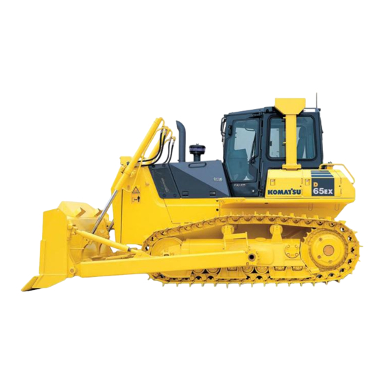
OPERATION GENERAL VIEW GENERAL VIEW GENERAL VIEW OF MACHINE Machine equipped with cab Machine equipped with canopy Blade Sprocket Tilt cylinder Pivot shaft Radiator mask Track frame Lift cylinder (10) Frame (11) Idler Track shoe (12) Canopy... -
Page 50: General View Of Controls And Gauges
OPERATION GENERAL VIEW GENERAL VIEW OF CONTROLS AND GAUGES Machine equipped with cab Fuel control lever (16) Service meter Cigarette lighter (17) Engine water temperature gauge Steering, directional and gear shift lever (18) Transmission oil temperature gauge Air conditioner panel or heater panel (19) Fuel gauge Head lamp switch (20) Transmission oil temperature caution lamp... - Page 51 OPERATION GENERAL VIEW Machine equipped with canopy Monitor panel specification Fuel control lever (13) Brake lock lever Steering, directional and gear shift lever (14) Service meter Head lamp switch (15) Engine water temperature gauge Rear lamp switch (16) Transmission oil temperature gauge Glow switch (17) Fuel gauge Speed range display lamp...
- Page 52 OPERATION GENERAL VIEW Machines equipped with canopy Gauge panel specification Fuel control lever (10) Horn switch Steering, directional and gear shift lever (11) Safety lock lever (for blade control lever) Head lamp switch (12) Brake lock lever Rear lamp switch (13) Engine water temperature gauge Speed range display lamp (14) Transmission oil temperature gauge...
-
Page 53: Explanation Of Components
OPERATION EXPLANATION OF COMPONENTS EXPLANATION OF COMPONENTS The following is an explanation of the devices needed for operating the machine. To carry out suitable operations correctly and safely, it is important to understand fully the methods of operating the equipment and the meanings of the displays. MONITOR PANEL (Monitor panel specification) Service meter... - Page 54 OPERATION EXPLANATION OF COMPONENTS ENGINE WATER TEMPEARTURE GAUGE This gauge (2) indicates the cooling water temperature. When the indicator is in the white range during operation, the water temperature is normal. If the indicator moves from the white range into the red range during operation, stop the machine immediately, run the engine under no load at a midrange speed, and wait for the indicator to go down to the white range.
- Page 55 OPERATION EXPLANATION OF COMPONENTS CHARGE LAMP This lamp (6) indicates malfunction of the alternator. When the starting switch is turned ON, it will light up, but it should go out when the engine speed rises. If the lamp lights up during operation, stop the engine and check the V-belt tension.
- Page 56 OPERATION EXPLANATION OF COMPONENTS MONITOR CAUTION LAMP This lamp (10) lights up when any of the following caution lamps lights up. In addition, the alarm buzzer sounds at the same time. Engine water temperature caution lamp Charge lamp Engine oil pressure caution lamp Transmission oil temperature caution lamp MONITOR CAUTION CANCAL SWITCH This switch (11) is used to cancel monitor caution lamp.
-
Page 57: Gauge Panel
OPERATION EXPLANATION OF COMPONENTS GAUGE PANEL (Gauge panel specification) Service meter Charge lamp Engine water temperature gauge Engine oil pressure caution lamp Transmission oil temperature gauge Glow signal lamp SERVICE METER This meter (1) shows the total number of hours the machine has operated. - Page 58 OPERATION EXPLANATION OF COMPONENTS TRANSMISSION OIL TEMPERATURE GAUGE This meter (3) shows transmission lubrication oil temperature. The temperature is normal, if the needle remains in the green range while in operation. If the needle goes into the red range while operating, stop the machine and let the engine idle with middle rpm and wait until the needle drops to the green range.
-
Page 59: Switches
OPERATION EXPLANATION OF COMPONENTS SWITCHES Machine equipped with cab Machine equipped with canopy Starting switch Additional working lamp switch Glow switch (machine equipped with cab) (if equipped) Horn switch Wiper switch (machine equipped with cab) Head lamp switch Room lamp (machine equipped with cab) Rear lamp switch Cigarette lighter (machine equipped with cab) 3-12... - Page 60 OPERATION EXPLANATION OF COMPONENTS STARTING SWITCH This switch (1) is used to start the engine. OFF position: At this position, the starting switch key can be inserted and removed. When the switch is turned to this position, all the electric circuits are turned off and the engine stops. ON position: In this position, electric current flows in the charging and lamp circuits.
- Page 61 OPERATION EXPLANATION OF COMPONENTS HORN SWITCH The horn sounds when the button (3) at the rear of the blade control lever at the right side of the operator’s seat is pressed. HEAD LAMP SWITCH This switch (4) lights up the head lamps. OFF position: Lamps are out ON position: Lamps light up REAR LAMP SWITCH...
- Page 62 OPERATION EXPLANATION OF COMPONENTS ADDITIONAL WORK LAMP SWITCH (Machine equipped with cab) (If equipped) This switch (6) is used to turn on the additional working lamp. (A)Head lamp switch (B)Rear lamp switch Push in the direction of the arrow to turn on the lamps. WIPER SWITCH (Machine equipped with cab) This switch (7) activates the wipers.
- Page 63 OPERATION EXPLANATION OF COMPONENTS Wiper only If this is switched on, the wiper will start. Wiper and window washer If this is kept pressed to the ON position while the wiper is working, water will be sprayed out. ROOM LAMP SWITCH (Machine equipped with cab) This lamp is used to turn on and off room lamp (8).
-
Page 64: Lamp
OPERATION EXPLANATION OF COMPONENTS LAMP Machine equipped with cab. Following illustration shows machine equipped with air conditioner. Machine equipped with canopy Speed range display lamp SPEED RANGE DISPLAY LAMP This lamp (1) indicates the currently selected gear speed range. When lamp 1 lights up: 1st When lamp 2 lights up: 2nd When lamp 3 lights up: 3rd 3-17... -
Page 65: Control Levers And Pedals
OPERATION EXPLANATION OF COMPONENTS CONTROL LEVERS AND PEDALS Safety lock lever (for blade control lever) Brake pedal Brake lock lever Decelerator pedal Fuel control lever Blade control lever Steering, directional and gear shift lever SAFETY LOCK LEVER (for blade control lever) WARNING When leaving the operator's seat, always set the safety lever securely to the LOCK position. - Page 66 OPERATION EXPLANATION OF COMPONENTS BRAKE LOCK LEVER WARNING When the machine is parked, always set the brake lock lever to the LOCK position. If the brake lock lever is operated, the brake operates even while the machine is traveling. Do not operate the brake lever while the machine is traveling since it stops the machine suddenly, but oper- ate it only in an emergency.
- Page 67 OPERATION EXPLANATION OF COMPONENTS STEERING, DIRECTIONAL AND GEAR SHIFT LEVER This lever (4) is used to select the direction of travel, to carry out steering, and to carry out counterrotation turns. Forward-reverse shifting Position (a): FORWARD Position (b): REVERSE Position N: NEUTRAL Steering Position (c): LEFT TURN Position (d): RIGHT TURN...
- Page 68 OPERATION EXPLANATION OF COMPONENTS As the gear is shifted, one of the gear speed lamps on the front panel lights up. 1st: Lamp 1 lights up. 2nd: Lamp 2 lights up. 3rd: Lamp 3 lights up. Counterrotation turn WARNING When carrying out a counterrotation turn, if the load is not equal on the left and right sides, the machine may carry out a pivot turn, so check the ground coditions and be careful not to hit any obsta- cles.
- Page 69 OPERATION EXPLANATION OF COMPONENTS DECELERATION PEDAL WARNING Do not place your foot on this pedal unnecessarily. When passing over the top of a hill or when a load is dumped over a cliff, the load is suddenly reduced, so there is danger that the travel speed will also increase suddenly. To prevent this, depress the decelerator pedal to reduce the travel speed.
- Page 70 OPERATION EXPLANATION OF COMPONENTS Tilting control (b) HOLD: Blade is stopped and held in this position. (e) LEFT TILT (f) RIGHT TILT POWERTILT POWER PITCHDOZER This lever (7) is used to lift or tilt and pitch the blade. Lifting control (a) RAISE: (b) HOLD: Blade is stopped and held in this position.
- Page 71 OPERATION EXPLANATION OF COMPONENTS Tilting control (e) LEFT TILT (f) RIGHT TILT Pitch control (b) HOLD: Blade is stopped and held in this position. (e) REAR PITCH:Min. digging angle (f) FORWARD PITCH:Max. digging angle First set the lever to the neutral position, then keep switch (A) in the center of the knod pushed down and carry out the tilt operation to change the cutting angle of the blade.
- Page 72 OPERATION EXPLANATION OF COMPONENTS Precautions when using pitch control When using the pitch operation, the tilt operation changes as follows. Pitch condition Tilt operation Amount of tilt Max.forward Only left tilt Max. 890mm (35 in) pitch operation is possible Compared with standard: Forward pitch LEFT tilt is LARGER...
-
Page 73: Fuse
OPERATION EXPLANATION OF COMPONENTS FUSE NOTICE Before replacing a fuse, be sure to turn off the starting switch. The fuses protect the electrical equipment and wiring from burning out. If the fuse becomes corroded, or white powder can be seen, or the fuse is loose in the fuse holder, replace the fuse. - Page 74 OPERATION EXPLANATION OF COMPONENTS Fuse box (2) Fuse capacity Name of circuit Cab radio Power pitch switching Air conditioner — — Chassis power source Fuse box (3) (Machine equipped with cab) Fuse capacity Name of circuit Radio memory Radio, lamp, cigarette lighter Rear window windshield wiper Right door windshield wiper Front window windshield wiper...
-
Page 75: Electric Power Take-Out Adapter
OPERATION EXPLANATION OF COMPONENTS ELECTRIC POWER TAKE-OUT ADAPTER NOTICE Do not use as a power supply for 12V equipment. This will cause failure of the equipment. When using as a power supply pickup, do not install equipment which exceeds 120W (24V x 5A). Open battery cover (1) on the left side of the machine. -
Page 76: Door-Open Lock
OPERATION EXPLANATION OF COMPONENTS DOOR-OPEN LOCK (Machine equipped with cab) Use this when your want to keep the door held open. Push the door against the door catch (1). The door will be held by the door catch. To release the door, move lever (2) inside the cab to the front of the cab. -
Page 77: Cap, Cover With Lock
OPERATION EXPLANATION OF COMPONENTS CAP, COVER WITH LOCK Use the starting switch key to open and close the caps and covers. For their locations , see "LOCKING (PAGE 3-94)". Insert the key as far as it will go to the shoulder. If the key is turned before it is inserted all the way, it may break. -
Page 78: Hot And Cool Box
OPERATION EXPLANATION OF COMPONENTS METHOD OF OPENING AND CLOSING COVER WITH LOCK TO OPEN THE COVER (LOCKED COVER) Insert the key into the key slot. Turn the key counterclockwise and open the cover by pulling the cover grip. TO LOCK THE COVER Close the cover and insert the key into the key slot. -
Page 79: Ashtray
OPERATION EXPLANATION OF COMPONENTS Machine not equipment with cab There is a pocket on the back of the operator's seat. Keep the operation manual in this pocket so that the operator can read it whenever necessary. ASHTRAY (Machine equipped with cab) This is on the left side of the operator's seat. -
Page 80: Air Conditioner
OPERATION EXPLANATION OF COMPONENTS AIR CONDITIONER (Machine equipped with cab, air conditioner) EXPLANATION OF PARTS Fresh/recirc selector lever Blower switch Air condition switch Temperature control lever FRESH/RECIRC SELECTOR LEVER This lever (1) changes the air intake port used when cooling or heating. - Page 81 OPERATION EXPLANATION OF COMPONENTS BLOWER SWITCH This switch (3) acts as the wind flow control switch and main switch when cooling or heating. The air flow can be set to three stages: 1 (LOW) → 2 (MEDIUM) → 3 (HIGH). If the switch is set to 0, the power is switched off and the air conditioner stops.
- Page 82 OPERATION EXPLANATION OF COMPONENTS COOLING OPERATION When the cooling operation is carried out, the inside of the cab is cooled, and at the same time the drinks inside the hot and cool box can be cooled. COOLING (RECIRC) When the control switch and lever are operated as shown in the diagram, a cool breeze is sent out.
- Page 83 OPERATION EXPLANATION OF COMPONENTS HEATING OPERATION When the heating operation is carried out, the inside of the cab is heated, and at the same time the drinks inside the hot and cool box can be heated. HEATING (RECIRC) When the control switch and lever are operated as shown in the diagram, warm air is sent out.
- Page 84 OPERATION EXPLANATION OF COMPONENTS PREVENTION METHOD OF ENTRY OF DUST Entry of dust into the cab can be prevented by starting the blower fan for the air conditioner to raise the pressure in the cab a little higher than outside. When working in a dusty job site or when preventing dust from entering the cab, use this function.
- Page 85 OPERATION EXPLANATION OF COMPONENTS PROCEDURE FOR REPLACING RECEIVER Replace the receiver once every two years. After replacing the receiver, add compressor oil. Turn the receiver at an angle and measure the oil remaining inside the receiver, then add the same amount of oil (Denso Oil 6) to fill the receiver. REMARK Depending on the condition of use, the replacement interval may be shorter.
-
Page 86: Heater
OPERATION EXPLANATION OF COMPONENTS HEATER (Machine equipped with cab, heater) EXPLANATION OF PARTS FRESH/RECIRC selector lever Temperature control lever Blower switch FRESH/RECIRC SELECTOR LEVER This lever (1) changes the air intake port used when cooling or heating. RECIRC: If lever (1) is shifted to the left, the air conditioner sucks inside air. - Page 87 OPERATION EXPLANATION OF COMPONENTS TEMPERATURE CONTROL LEVER This lever (3) is used to control the temperature for heating. When the temperature control lever is moved to the right, the temperature of the air coming from the vents becomes lower. When the temperature control lever is moved to the left, the temperature of the air coming from the vents becomes higher.
- Page 88 OPERATION EXPLANATION OF COMPONENTS CREANING AIR FILTER If the air filter for the FRESH or RECIRC air intake becomes clogged, the heating capacity will drop. In places where there is a lot of dust, clean the air with compressed air once a week. For details of the cleaning method, see "CLEAN AIR CONDITIONER AIR FILTER (FRESH/RECIRC FILTER) (PAGE 4-51)".
-
Page 89: Operation
Check carefully, and if any abnormality is found, repair it or contact your Komatsu distributor. Do not get on or off the machine from the rear. Using this position is dangerous because it is easy to slip and you cannot be seen from the operator's compartment. - Page 90 OPERATION OPERATION Check for damage to gauges, lamps on instrument panel, loose bolts Check that there is no damage to the panel, gauges and lamps. If any abnormality is found, replace the parts. Clean off any dirt on the surface. Seat belt and mounting clamps Check that there is no abnormality in the seat belt or mounting clamps.
- Page 91 OPERATION OPERATION CHECK BEFORE STARTING Always carry out the items of the checks in this section before starting the engine each day. CHECK COOLANT LEVEL, ADD WATER WARNING Do not open the radiator cap unless necessary. When checking the coolant, always wait for the engine to cool down and check the sub tank.
- Page 92 2 seconds, and the alarm buzzer sounds for 1 second. REMARK If the lamps do not light up, there may be a failure or discon- nection in the monitor, so please contact your Komatsu distrib- utor. 3-45...
- Page 93 If any lamp does not light up or two or more lamps light up, or if the lighting lamp does not change even the gear is shifted, the gear speed lamp system or its wire may be broken. In this case, call your Komatsu distributor and ask for inspection. 3-46...
- Page 94 OPERATION OPERATION CHECK FUEL LEVEL, ADD FUEL WARNING When adding fuel, never spill the oil or let it overflow. It can catch fire. If any fuel is spilled, wipe it up com- pletely. If fuel has spilled over soil or sand, remove that soil or sand. Fuel is highly flammable and dangerous.
- Page 95 OPERATION OPERATION NOTICE If breather hole (1) in the cap is clogged, the pressure inside the tank will drop and fuel will not flow. Clean breather (1) from time to time and check that it is not clogged. CHECK OIL LEVEL IN ENGINE OIL PAN, ADD OIL WARNING The parts and oil are at high temperature after the engine is stopped, and may cause serious burns.
- Page 96 Depress the brake pedal all the way until it stops. The distance of travel at the center of the pedal should be 70 to 90mm (2.8 to 3.5in). When this value exceeds 91mm (3.6in), or the brake fails to work, please contact your Komatsu distributor for adjustment. 3-49...
- Page 97 Be particularly careful to check the wiring of the battery, starting motor, and alternator. Always check also that there is no flammable material accumulated around the engine. Remove any such flamma- ble material. Please contact your Komatsu distributor for advice on investigation and correction of the cause. 3-50...
- Page 98 Check that the head lamp, rear lamp, additional working lamp (if equipped), and instrument lamp light up normally and they are free from stain and damage. If the lamps do not light up, there is probably a broken bulb or disconnection in the wiring, so contact your Komatsu distributor for repairs.
- Page 99 Check that the horn sounds. If it does not sound at all or the sound is extremely feeble, a defect or broken wire is suspected, ask your Komatsu distributor for possible repairs. Insert the key into starting switch and turn the key to the ON position.
- Page 100 OPERATION OPERATION Set the brake lock lever to the FREE position. Set the steering, directional and gear shift lever in the REVERSE position. The buzzer must sound immediately at this time. The buzzer keeps sounding until the steering, directional and gear shift lever is set to the NEUTRAL or FORWARD position.
- Page 101 OPERATION OPERATION CHECK FOR WATER AND SEDIMENT IN WATER SEPARATOR, DRAIN WATER (If equipped) The water separator separates water mixed in the fuel. If float (2) is at or above red line (1) , drain the water according to the following procedure.
- Page 102 OPERATION OPERATION ADJUSTMENT ADJUST OPERATOR'S SEAT WARNING Adjust the seat position at the beginning of each shift or when operators change. Adjust the seat so that the brake pedal can be depressed all the way with the operator’s back against the backrest.
- Page 103 OPERATION OPERATION ADJUST ARM REST The height of the armrests on both sides of the operator's seat can be adjusted to three levels. After adjusting the operator's seat, adjust the height of the armrests properly. Loosen knobs (1) on both sides of the operator's seat. Move the armrests on both sides of the operator's seat forward, then adjust their height to (H), (M), or (L).
- Page 104 OPERATION OPERATION USING SEAT BELT Always install a seat belt on machines equipped with ROPS. WARNING Before fitting the seat belt, check that there is no abnormality in the mounting bracket and mounting belt of the belt. If the belt is worn or damaged, replace it. Replace the seat belt every three years, even if their outside is free from abnormality.
- Page 105 OPERATION OPERATION OPERATION AND CHECK BEFORE STARTING ENGINE WARNING When starting the engine, check that the safety lock lever is securely at the LOCK position. If the control levers are not locked and they are touched by accident when starting the engine, the work equipment may move unexpectedly, and this may lead to a serious accident.
- Page 106 OPERATION OPERATION Insert the key into starting switch (2) and turn the key to the ON position. Check that speed range display lamp (3) shows 1st. Check that steerling, directional and gear shift lever (4) is at the N (neutral) position. Check that the blade is lowered to the ground and that blade control lever (5) is at the HOLD position.
-
Page 107: Starting Engine
OPERATION OPERATION STARTING ENGINE NORMAL STARTING WARNING Check that there are no persons or obstacles in the surrounding area, then sound the horn and start the engine. Exhaust gas is toxic. When starting the engine in con- fined spaces, be particularly careful to ensure good ventilation. - Page 108 OPERATION OPERATION When the engine starts, release the key in starting switch (2). The key will return automatically to the ON position. Continue idling for 10 seconds after the engine starts. During this time, do not operate the control levers or fuel control lever.
- Page 109 OPERATION OPERATION Before starting the engine, check that fuel control lever (1) is at the low idling position. Pull fuel control lever (1) to a position midway between the low idling and full speed positions. Insert the key into starting switch (2) and turn the key to the ON position.
- Page 110 OPERATION OPERATION AUTOMATIC PREHEATING Turn glow switch (3) to the AUTO position. When it is turned to the AUTO position, preheating is automatically carried out according to the ambient tem- perature. Lamp (4) lights up during the preheating opera- tion. When the preheating is completed, lamp (4) will go out.
- Page 111 OPERATION OPERATION MANUAL PREHEATING Turn glow switch (3) to position I or II. Lamp (4) lights up during the preheating operation. When the preheating is completed, release the switch. The key will then return automatically to the following position. From position I, it will return to AUTO From position II, it will return to OFF The preheating times are as shown below.
- Page 112 OPERATION OPERATION GAUGE PANEL SPEC. NOTICE Do not start the engine with the fuel control lever near the FULL position. There is danger that this will damage the engine parts. Do not keep the starting motor rotating continuously for more than 20 seconds. If the engine fails to start, repeat steps 2 and 3 after waiting for about 2 minutes.
- Page 113 OPERATION OPERATION The preheating times are as shown below. Ambient temperature Preheat time 0ºC to -5ºC (32°F to 23°F) -5ºC to -10ºC 15 seconds (23°F to 14°F) -10ºC to -20ºC 30 seconds (14°F to -4°F) -20ºC to -30ºC 45 seconds (-4°F to -22°F) If the preheating time is too long or too short, the engine will not start easily.
-
Page 114: Operations And Checks After Starting Engine
OPERATIONS AND CHECKS AFTER STARTING ENGINE BREAKING IN THE NEW MACHINE CAUTION Your Komatsu machine has been thoroughly adjusted and tested before shipment. However, operating the machine under severe conditions at the beginning can adversely affect the performance and shorten the machine life. - Page 115 OPERATION OPERATION Pull fuel control lever (1) to the center position between LOW IDLING and HIGH IDLING and run the engine at medium speed for about 5 minutes with no load. After warm-up has completed, check gauges and caution lamps for proper operation. If any abnormality is found, repair it.
- Page 116 OPERATION OPERATION STARTING IN COLD WEATHER After starting the engine, do not immediately start operations. First, carry out the following operations and checks. NOTICE Avoid abrupt acceleration until warm-up run is completed. Do not run the engine at low idling or high idling for more than 20 minutes.
-
Page 117: Stopping Engine
OPERATION OPERATION After warm-up has completed, check gauges and caution lamps for proper operation. If any abnormality is found, repair it. Continue to run the engine at low load until engine water temperature gauge (2) falls within the white range (Moni- tor Panel Spec.) or green range (Gauge Panel Spec.). - Page 118 OPERATION OPERATION Place fuel control lever (1) in the low idling position and run the engine at low idling speed for about 5 minutes to allow it to gradually cool down. Place fuel control lever (1) in the engine stop position and stop the engine.
-
Page 119: Check After Stopping Engine
OPERATION OPERATION CHECK AFTER STOPPING ENGINE Walk around the machine and check the work equipment, machine exterior, and undercarriage, and check also for leakage of oil or water. If any abnormalities are found, repair them. Fill the fuel tank. Check the engine compartment for paper and debris. Clean out any paper and debris to avoid a fire hazard. Remove any mud affixed to the undercarriage. -
Page 120: Machine Operation
OPERATION OPERATION MACHINE OPERATION MOVING MACHINE OFF WARNING When starting the machine off, check that the area around the machine is safe and sound the horn before moving. Do not allow people to enter the area around the machine. The area at the rear of the machine is a blind spot, so be extremely careful when reversing the machine. - Page 121 OPERATION OPERATION Operate steering, directional and gear shift lever (4) to the desired position, and check that speed range display lamp (3) shows the correct position. Pull the safety lock lever (6) to the free position. Put blade control lever (5) in the RAISE position to raise the blade 40 to 50mm (1.6 to 2.0in) off the ground.
- Page 122 OPERATION OPERATION STOPPING MACHINE WARNING Avoid stopping suddenly. Give yourself ample room when stopping. Depress brake pedal (1) to stop the machine. Place steering, directional and gear shift lever (2) in the N (neutral) position. 3-75...
- Page 123 OPERATION OPERATION Operate steering, directional and gear shift lever (2) to 1st, and check that speed range display lamp (3) shows the correct position. 3-76...
-
Page 124: Shifting Gaer
OPERATION OPERATION SHIFTING GAER There is no need to stop machine to shift gears. Set steering, directional and gear shift lever (1) in the desired position to shift gear. Gear shifting Rotate Steering, directional and gear shift lever 30º to carry out gear shifting operation. -
Page 125: Shifting Between Forward And Reverse
OPERATION OPERATION SHIFTING BETWEEN FORWARD AND REVERSE CAUTION The travel direction can be changed without stopping the machine. Do not change it while the engine is running at the full speed, however, but depress the decelerator pedal to lower the engine speed before changing the travel direction for safety, comfort, and longer life of the power train. - Page 126 For machines equipped with a backup alarm, check that the backup alarm sounds when steering, directional and gear shift lever (4) is placed in REVERSE. If the alarm does not sound, please contact your Komatsu distributor.
-
Page 127: Steering Machine
OPERATION OPERATION STEERING MACHINE WARNING Avoid as much as possible turning the machine on a slope. The machine will tend to slip sideways. Particular care should be taken on soft or clay land. Never try to turn the machine sharply when traveling at high speed. NORMAL TURNING WARNING The feeling of the operation if the operator carries out a counterrotation turn when your head is facing the... - Page 128 OPERATION OPERATION TURNING TO LEFT WHILE TRAVELING FORWARD NOTICE If the lever is operated partially to the forward or reverse position and then is operated in the direction of turn, the machine may carry out a counterrotation turn, so operate the lever fully to the forward or reverse position.
- Page 129 OPERATION OPERATION TURNING WHILE DESCENDING A SLOPE This machine (which can turn by counterrotation) does not cross-steer even when it descends a steep slope where it is driven down by its own weight or when it is pushed down by a towed machine on a slope. Accordingly, descend a slope as explained below.
- Page 130 OPERATION OPERATION WHEN MAKING A PIVOT TURN TO THE LEFT WHILE TRAVELING If the steering, directional and gear shift lever (1) is pushed for- ward and moved fully to the left (L), the machine turns sharply to the left. (Does not become reverse steering) REMARK When making sharp turns to the right, push the steering, direc- tional and gear shift lever (1) forward, and move it fully to the...
-
Page 131: Precautions For Operation
OPERATION OPERATION PRECAUTIONS FOR OPERATION PERMISSIBLE WATER DEPTH When operating in water, always keep the bottom of carrier roller (1) above the surface of the water. Also, be careful that the engine cooling fan will not come in contact with water. The fan can be damaged. - Page 132 OPERATION OPERATION IT IS PROHIBITED TO MODIFY THE CAB GLASS IN ANY WAY THAT OBSTRUCT THE VIEW (Machine equipped with cab) For safety reasons, do not install anything to the cab glass that will obstruct the view. Always keep the glass clean to ensure safety during operations. PRECAUTIONS FOR BLIND SPOTS CAUSED BY CAB STAY WARNING The cab stay cause blind spots.
-
Page 133: Work Possible Using Bulldozer
OPERATION OPERATION WORK POSSIBLE USING BULLDOZER In addition to the following, it is possible to further increase the range of applications by using various attachments. DOZING A bulldozer digs and transports dirt in a forward direction. Slope excavation can always be most effectively carried out by proceeding from the top downward. - Page 134 OPERATION OPERATION CUTTING INTO HARD OR FROZEN GROUND OR DITCHING For digging and ditch excavation of hard or frozen ground, tilt the blade. Even hard ground can be dug effectively by a tilted or angled blade. FELLING TREES, REMOVING STUMPS NOTICE Do not up root trees or stumps or fell trees by angling or tilting the blade.
- Page 135 OPERATION OPERATION Raise the blade 300 to 400 mm (11.8 to 15.8 in) above the ground, then put blocks under the frame so that the blade does not come down. Remove pins (1) on the left and right sides, then remove arm (2) from the frame.
- Page 136 OPERATION OPERATION ADJUST AMOUNT OF TILT POWER TILT (Angledozers only) WARNING When adjusting the amount of tilt, it is dangerous if the work equipment is moved by mistake. Set the work equipment in a safe condition, then stop the engine and lock the work equipment securely with the safety lock lever.
- Page 137 OPERATION OPERATION ADJUST ANGLE OF BLADE EDGE (Power tiltdozer only) WARNING It is dangerous if the work equipment moves by mistake when adjusting angle of the blade edge. Set the work equipment in a stable condition, then stop the engine and lock the work equipment securely with the safety lock lever.
- Page 138 OPERATION OPERATION PROCEDURE FOR ADJUSTING SHIM WHEN ASSEMBLING WORK EQUIP- MENT When assembling the work equipment, adjust the play at all parts to the correct value. Adjustment portion Tilt Lift Center Trunnion Item 0.2 to 0.5 0.2 to 0.5 0.2 to 0.5 0.2 to 1.0 Correct value (mm) (0.008 to...
-
Page 139: Parking Machine
OPERATION OPERATION PARKING MACHINE WARNING Avoid stopping suddenly. Give yourself ample room when stopping. When stopping the machine, select flat hard ground and avoid dangerous places. If it is unavoidably necessary to park the machine on a slope, place the parking lever in the LOCK position and insert blocks underneath the track shoes. -
Page 140: Check After Finishing Work
OPERATION OPERATION Operate blade control lever (2) to the LOWER position, and lower the blade to the ground. Set safety lock lever (3) to the LOCK position. CHECK AFTER FINISHING WORK Use the meters and caution lamps to check the engine water temperature, engine oil pressure, fuel level, and transmission oil temperature. -
Page 141: Locking
OPERATION OPERATION LOCKING To prevent vandalism, there are locks at the following places. Places that can be locked with the starting switch key. Top cover at front of chassis (1) Right and left engine side cover (2) Battery inspection cover (3) Inspection cover for fuel tank drain valve (4) Cab door opener (5) (machines equipped with cab) Fuel tank filler cap (6) -
Page 142: Tips For Longer Undercarriage Life
OPERATION METHOD Select the track shoe that best suits the type of soil to be encountered in service. Please consult your Komatsu distributor when selecting track shoes. Do not allow shoe slipping to occur during operation. If shoe slipping occurs, reduce load to the blade until slipping stops. - Page 143 OPERATION OPERATION INSPECTION AND ADJUSTMENT Properly adjust track tension. Check the track tension by measuring clearance A between the idler and carrier roller shown in the figure at right. Clearance A should be 20 to 30mm (0.8 to 1.2in) nor- mally.
- Page 144 Frequent inspection and prompt repair will reduce repair costs. The following items for inspection will serve as a guide to maintenance service of each undercarriage part. Per- form periodical inspection and contact the Komatsu distributor in your area when machine has approached repair- able limits and reversing limits.
- Page 145 OPERATION OPERATION MEASURING OUTSIDE DIAMETER OF TRACK ROLLER Measure height (size C) of link tread as shown. Stop machine at position where link tread, whose size C has been measured completely, contacts roller tread. Then measure size B. Calculate outside diameter of tread (size A): A = (B - C) x 2 Standard size (A): 210 mm (8.3 in) Repair limits: 172 mm (6.8 in)
-
Page 146: Transportation
If it is necessary to remove the cab for transportation, there is danger that the seal may be damaged when remov- ing or installing the cab, so please contact your Komatsu distributor. When installing the cab, please contact your Komatsu distributor, too. - Page 147 OPERATION TRANSPORTATION Remove the left and right trunnions. (D65PX and D65EX wide gauge specified) REMARK In the case of D65PX, remove the left and right trunnions. In the case of D65EX, the width including the left and right trunnions is within 3.0 m (118.1 in), so there is no need to remove them.
-
Page 148: Loading, Unloading Work
OPERATION TRANSPORTATION LOADING, UNLOADING WORK WARNING Since loading and unloading of the machine is dangerous, be extremely careful. When loading or unloading the machine, operate it slowly with the engine speed low and the trans- mission in the 1st gear. Use ramps having sufficient width, length, thickness, and strength. - Page 149 OPERATION TRANSPORTATION SECURING MACHINE WARNING When the edge of the blade protrudes beyond the trailer, angle the blade. (Angledozer) NOTICE Be sure to retract the car radio antenna (if the machine equipped with cab). Load the machine on to a trailer as follows. Lower the work equipment slowly.
- Page 150 OPERATION TRANSPORTATION Put blocks in front and behind the track shoes of both sides. Set up chain or wire, following (A) or (B). A: Set up chain or wire through the holes of track links. B: Set up chain or wire around the track shoes. Protect the wire from contacting directly with angular parts of the machine, by inserting pads.
- Page 151 OPERATION TRANSPORTATION UNLOADING Perform loading and unloading on firm, level ground only. Maintain a safe distance from the edge of a road. Properly apply the brakes on the trailer and put blocks under the tires to ensure that the trailer does not move. Then fix the ramps in line with the centers of the trailer and the machine.
-
Page 152: Lifting Machine
The lifting procedure applies to machines with standard specifications. The method of lifting differs according to the attachments and options actually installed. In such cases, please contact your Komatsu distributor for information. For details of the weight, see "SPECIFICATIONS (PAGE 5-2)". - Page 153 OPERATION TRANSPORTATION For machine equipped with ripper When lifting the machine, stop it on a level place, then observe the following procedure. Stop the engine and set the brake lock lever to the LOCK position. Install wire ropes, slings, etc. matched to the weight of the machine to the lifting points as shown in the above figure.
-
Page 154: Cold Weather Operation
Antifreeze is toxic. Be extremely careful when handling it. When replacing coolant containing anti- freeze or when handling coolant when repairing the radiator, contact your Komatsu distributor or ask your local antifreeze dealer. Be careful not to let the water flow into drainage ditches or spray on to the ground surface. - Page 155 OPERATION COLD WEATHER OPERATION BATTERY WARNING The battery generates flammable gas, so do not bring fire or sparks near the battery. Battery electrolyte is dangerous. If it gets in your eyes or on your skin, wash it off with large amounts of water, and consult a doctor.
-
Page 156: After Completion Of Work
OPERATION COLD WEATHER OPERATION AFTER COMPLETION OF WORK WARNING After completion of operations, fill the fuel tank to prevent the formation of water caused by condensation of moisture in the empty space in the tank when the temperature goes down. To prevent mud, water, or the undercarriage from freezing and making it impossible for the machine to move on the following morning, always observe the following precautions. -
Page 157: Long-Term Storage
NOTICE If the machine is to be used when the monthly rust prevention operation has not been carried out, please contact your Komatsu distributor. When using the machine after long-term storage, do as follows before using it. Wipe off the grease from the hydraulic cylinder rods. -
Page 158: Troubleshooting
OPERATION TROUBLESHOOTING TROUBLESHOOTING AFTER RUNNING OUT OF FUEL When starting after running out of fuel, fill with fuel and bleed the air from the fuel system before starting. For details of bleeding the air, see "REPLACE FUEL FILTER CARTRIDGE (PAGE 4-52)". TOWING THE MACHINE WARNING Be sure to use a wire rope sufficiently strong for the towing weight. -
Page 159: If Battery Is Discharged
OPERATION TROUBLESHOOTING IF BATTERY IS DISCHARGED WARNING When checking or handling the battery, stop the engine and turn the starting switch key to the OFF position. The battery generates hydrogen gas, so there is a haz- ard of explosion. Do not bring lighted cigarettes near the battery, or do anything that will cause sparks. - Page 160 OPERATION TROUBLESHOOTING REMOVE AND INSTALL BATTERY Open battery cover (1), remove 4 bolts (2) on the inside, then remove cover (1). Before removing battery, remove the ground cable (nor- mally connected to the negetive (-) terminal). If any tool touches between the positive terminal and the chassis, there is danger of sparks being generated.
- Page 161 OPERATION TROUBLESHOOTING STARTING ENGINE WITH BOOSTER CABLE When starting the engine with a booster cable, do as follows: PRECAUTIONS WHEN CONNECTING AND DISCONNECTING BOOSTER CABLE WARNING When connecting the cables, never contact the posi- tive (-) and negative (+) terminals. When starting the engine with a booster cable, always wear safety glasses and rubber gloves.
- Page 162 OPERATION TROUBLESHOOTING STARTING ENGINE CAUTION Always check that the safety lock lever is set to the LOCK position, regardless of whether the machine is working normally or has failed. Check also that all the control levers are at the HOLD or neutral position. Make sure the clips are firmly connected to the battery terminals.
-
Page 163: Other Trouble
OPERATION TROUBLESHOOTING OTHER TROUBLE ELECTRICAL SYSTEM ( ): Always contact your Komatsu distributor when dealing with these items. In cases of abnormalities or causes which are not listed below, please contact your Komatsu distributor for repairs. Problem Main causes Remedy... - Page 164 OPERATION TROUBLESHOOTING Problem Main causes Remedy Defective wiring Check, repair) Blade does not pitch when pitch is oper- Defective switch Replace) ated (pitch specification only) Defective solenoid valve Replace) 3-117...
- Page 165 OPERATION TROUBLESHOOTING CHASSIS ( ): Always contact your Komatsu distributor when dealing with these items. In cases of abnormalities or causes which are not listed below, please contact your Komatsu distributor for repairs. Problem Main causes Remedy When brake pedal is depress,...
- Page 166 OPERATION TROUBLESHOOTING Problem Main causes Remedy Lack of oil in power train case Add oil to specified level, see CHECK BEFORE STARTING Transmission oil pressure dose See "Transmission oil pres- Torque converter overheats not rise sure dose not rise" above (indicator enters red range) Wear, scuffing of gear pump Check, repair)
- Page 167 OPERATION TROUBLESHOOTING ENGINE ( ): Always contact your Komatsu distributor when dealing with these items. In cases of abnormalities or causes which are not listed below, please contact your Komatsu distributor for repairs. Problem Main causes Remedy Engine oil pan oil level is low...
- Page 168 OPERATION TROUBLESHOOTING Problem Main causes Remedy Low grade fuel being used Change to specified fuel Overheating See item "Indicator of water tem- Abnormal noise generated perature gauge is in red range (combustion or mechanical) on right side of gauge" Damage inside muffler Replace muffler) Excessive valve clearance Adjust valve clearance)
-
Page 169: Maintenance
MAINTENANCE WARNING Please read and make sure that you understand the safety volume before reading this section. -
Page 170: Guide To Maintenance
KOMATSU GENUINE REPLACEMENTPARTS: Use Komatsu genuine parts specified in the Parts Book as replacement parts. KOMATSU GENUINE OILS: Use Komatsu genuine oils and grease. Choose oils and grease with proper viscosities specified for ambient tem- perature. ALWAYS USE CLEAN WASHER FLUID: Use automobile windshield washer fluid, and be sure not to let any dirt get into it. - Page 171 MAINTENANCE GUIDE TO MAINTENANCE DO NOT DROP THINGS INSIDE MACHINE: When opening inspection windows or the oil filler port of the tank to carry out inspection, be careful not to drop nuts, bolts, or tools inside the machine. If such things are dropped inside the machine, it will cause damage and malfunction of the machine, and will lead to failure.
- Page 172 MAINTENANCE GUIDE TO MAINTENANCE LOOKING THE INSPECTION COVERS: When carrying out maintenance with the inspection cover open, lock it in position securely with a lock bar. If inspection or maintenance is carried out with the inspection cover open and not locked in position, there is a haz- ard that it may be suddenly blown shut by the wind and cause injury to the worker.
-
Page 173: Outline Of Service
When changing the oil, always replace the related filters at the same time. We recommend you to have an analysis made of the oil periodically to check the condition of the machine. For those who wish to use this service, please contact your Komatsu distributor. FUEL The fuel pump is a precision instrument, and if fuel containing water or dirt is used, it cannot work properly. - Page 174 When using anti-freeze, always observe the precautions given in the Operation and Maintenance Manual. Komatsu machines are supplied with Komatsu original anti-freeze in the coolant when the machine is shipped. This anti-freeze is effective in preventing corrosion of the cooling system.
- Page 175 Carry out sampling regularly at fixed intervals. Do not carry out sampling on rainy or windy days when water or dust can get into the oil. For further details of KOWA, please contact your Komatsu distributor. STORING OIL AND FUEL Keep indoors to prevent any water, dirt, or other impurities from getting in.
-
Page 176: Relating To Electric System
Service relating to the electric system is check of fan belt tension, check of damage or wear in the fan belt and check of battery fluid level. Never install any electric components other than there specified by Komatsu. External electrical interference may cause malfunction of the control system controller, so before installing a radio receiver or other wireless equipment, please contact your Komatsu distributor. - Page 177 MAINTENANCE OUTLINE OF SERVICE Inspection and maintenance includes inspection of the hydraulic oil level, replacement of filters, and changing the hydraulic oil. When removing high-pressure hoses, check that there is no damage to the O-ring. If any damage is found, replace.
-
Page 178: Wear Parts
The wear parts should be changed correctly in order to use the machine economically. When changing parts,use Komatsu genuine parts of excellent quality. When ordering parts, please check the part number in the parts book. - Page 179 MAINTENANCE WEAR PARTS Weight Item Part No. Part Name Q'ty Replacement (kg) 14X-71-11310 Cutting edge 38.4 144-71-11330 End bit (left) D65EX 144-71-11340 End bit (right) Tilt dozer (02090-11270) (Bolt) (28) (02290-11219) (Nut) (28) 14Y-71-11210 Cutting edge 45.5 D65PX 14Y-71-11330 End bit (left) Tilt dozer 14Y-71-11340 End bit (right)
-
Page 180: Use Of Fuel, Coolant And Lubricants According To Ambient Temperature
MAINTENANCE USE OF FUEL, COOLANT AND LUBRICANTS ACCORDING TO AMBIENT TEMPERATURE USE OF FUEL, COOLANT AND LUBRICANTS ACCORDING TO AMBIENT TEMPERATURE PROPER SELECTION OF FUEL, COOLANT AND LUBRICANTS 4-12... - Page 181 There is no problem if single grade oil is mixed with multigrade oil (SAE10W-30, 15W-40), but be sure to add single grade oil than matches the temparature in the table. We recommend Komatsu genuine oil which has been specifically formulated and approved for use in engine and hydrauric work equipment applications.
- Page 182 SAE80, 90, 140 NLGI No.2 Base] (The 15W40 oil Permanent Type marked * is CE.) EO10-CD AF-ACL EO30-CD GO90 G2-LI AF-PTL KOMATSU EO10-30CD GO140 G2-LI-S AF-PT (Winter, one EO15-40CD season type) Diesel sigma S super dieselmulti- AGIP Rotra MP GR MU/EP...
- Page 183 MAINTENANCE USE OF FUEL, COOLANT AND LUBRICANTS ACCORDING TO AMBIENT TEMPERATURE Engine Oil Anti-freeze [CD or CE] Gear Oil Grease Coolant SAE10W, 30, 40 Supplier [GL-4 or GL-5] [Lithium-Base] [Ethylene Glycol 10W30, 15W40 SAE80, 90, 140 NLGI No.2 Base] (The 15W40 oil Permanent Type marked * is CE.) FINA potonic N...
-
Page 184: Standard Tightening Torques For Bolts And Nuts
The tightening torque is determined by the width across the flats of the nut and bolt. If it is necessary to replace any nut or bolt, always use a Komatsu genuine part of the same size as the part that was replaced. -
Page 185: Periodic Replacement Of Safety Critical Parts
These parts are particularly closely connected to safety and fire prevention, so please contact your Komatsu distributor to have them replaced. With these parts, the material changes as time passes, or they easily wear out or deteriorate. However, it is difficult to judge the condition of the parts simply by periodic maintenance, so they should always be replaced after a fixed time has passed, regardless of their condition. -
Page 186: Safety Critical Parts
MAINTENANCE PERIODIC REPLACEMENT OF SAFETY CRITICAL PARTS SAFETY CRITICAL PARTS Safety critical parts for periodic replacement Q'ty Replacement interval Fuel hose (fuel tank - injection pump) Fuel hose (injection pump - fuel filter) Feul return hose (injection pump - fuel tank) Fuel return hose (injection nozzle - fuel tank) Hose (PPC charge valve - PPC valve) Hose (hydraulic tank - PPC valve) -
Page 187: Maintenance Schedure Chart
MAINTENANCE MAINTENANCE SCHEDURE CHART MAINTENANCE SCHEDURE CHART MAINTENANCE SCHEDURE CHART WHEN REQUIRED CHECK, CLEAN AND REPLACE AIR CLEANER ELEMENT 4-21 CLEAN INSIDE OF COOLING SYSTEM......................4-25 CHECK TRACK TENSION ..........................4-28 CHECK AND TIGHTEN TRACK SHOE BOLTS ....................4-29 CHECK ELECTRICAL INTAKE AIR HEATER ....................4-30 REVERSE AND REPLACE THE END BITS AND CUTTING EDGES.............. - Page 188 MAINTENANCE MAINTENANCE SCHEDURE CHART REPLACE POWER TRAIN OIL FILTER ELEMENT ................... 4-48 CHECK BRAKE PERFORMANCE ........................4-50 CLEAN AIR CONDITIONER AIR FILTER (FRESH/RECIRC FILTER) ............... 4-51 EVERY 500 HOURS SERVICE REPLACE FUEL FILTER CARTRIDGE ......................4-52 METHOD OF USING AUTOMATIC AIR BLEED MECHANISM................4-53 CHANGE OIL IN ENGINE OIL PAN, REPLACE ENGINE OIL FILTER CARTRIDGE ........
-
Page 189: Service Procedure
MAINTENANCE SERVICE PROCEDURE SERVICE PROCEDURE WHEN REQUIRED CHECK, CLEAN AND REPLACE AIR CLEANER ELEMENT WARNING If inspection, cleaning, or maintenance is carried out with the engine running, dirt will get into the engine and the engine will suffer damage. Always stop the engine before carrying out these opera- tions. - Page 190 MAINTENANCE SERVICE PROCEDURE CLEANING OUTER ELEMENT Open the left engine side cover. Loosen bolt (2), remove cover (3). Remove the wing nut (4) and the seal washer (5), and take out the outer element (6). Clean the air cleaner housing interior and the cover. Direct dry compressed air (less than 0.69MPa (7kg/cm ,99.4 PSI)) to the outer element from inside along its folds, then direct it from outside along its folds and again...
- Page 191 MAINTENANCE SERVICE PROCEDURE Install the cleaned element and secure it with wing nut (5) and seal washer (4). If seal washer (4) or threads of wing nut (5) are damaged or have any defect, replace with new one. Remove the evacuator valve (11), clean with dry compressed air and then reinstall it. Install the cover (3).
- Page 192 MAINTENANCE SERVICE PROCEDURE Install a new outer element (6) and secure it with the wing nut (4) and seal washer (5). 10. Remove the evacuator valve (11), clean with dry compressed air and then reinstall it. 11. Install the cover (3). 12.
-
Page 193: Clean Inside Of Cooling System
MAINTENANCE SERVICE PROCEDURE CLEAN INSIDE OF COOLING SYSTEM WARNING Just after the engine is stopped, the cooling water is still hot and the internal pressure in the radiator is still high. If the radiator cap is removed under this condition, you may scald yourself. Accordingly, wait until the temperature lowers, then loosen the cap slowly to release the pressure. - Page 194 If it gets in your eyes, flush your eyes with large quantities of fresh water and see a doctor at once. Use city water for the cooling water. If river water, well water or other such water supply must be used, contact your Komatsu distributor. We recommend use of an antifreeze density gauge to control the mixing proportions.
- Page 195 MAINTENANCE SERVICE PROCEDURE 11. Drain the cooling water inside sub-tank (4), clean the inside of the sub-tank, then fill again with cooling water to a point midway betwee the FULL and LOW marks. 12. Stop the engine and tighten the cap. Check the coolant level and add water if necessary.
-
Page 196: Check Track Tension
Furthermore, do not bring your face in front of the grease fitting. If the track tension is not relieved by this procedure, please contact your Komatsu distributor. WHEN INCREASING TENSION Prepare a grease gun. Pump in grease through the grease fitting (2) with a grease pump. -
Page 197: Check And Tighten Track Shoe Bolts
Continue to pump in grease until S becomes 0mm. If the tension is still loose, the pin and bushing are excessively worn, so they must be either turned or replaced. Please contact your Komatsu distributor. WHEN LOOSENING TENSION WARNING It is extremely dangerous to release the grease by any method except the procedure given below. -
Page 198: Check Electrical Intake Air Heater
Tighten the bolts in the order shown in the diagram on the right. CHECK ELECTRICAL INTAKE AIR HEATER Before the start of the cold season (once a year), contact your Komatsu distributor to have the electrical intake air heater repaired or checked for dirt or disconnections. -
Page 199: Reverse And Replace The End Bits And Cutting Edges
MAINTENANCE SERVICE PROCEDURE REVERSE AND REPLACE THE END BITS AND CUTTING EDGES WARNING It is dangerous if the work equipment moves by mistake when the cutting edges and end bits are being reversed or replaced. Set the work equipment in a stable condition, then stop the engine and lock the blade control lever securely with the safety lock lever. - Page 200 MAINTENANCE SERVICE PROCEDURE The symbols in the work equipment column have the following meaning. A: Powertilt dozer (D65EX) B: Powertilt dozer (D65PX) C: Powertilt, Power pitch dozer (D65PX) D: Semi-U blade (3m) (D65EX) E: Semi-U blade (D65EX) (D65EX wide gauge specified) F: Angledozer (D65EX) REMARK If the cutting edge and the end bit on both sides are worn out, replace with new one.
-
Page 201: Clean, Check Radiator Fins
MAINTENANCE SERVICE PROCEDURE CLEAN, CHECK RADIATOR FINS Remove bolts (1) (4 bolts). Open the A side (hinge side) of the radiator mask. It opens approx. 10 mm (0.4 in). Open the B side of the radiator mask. Clean the radiator fins clogged with mud, dust and leaves with compressed air. -
Page 202: Check, Adjust Air Conditioner
MAINTENANCE SERVICE PROCEDURE CHECK, ADJUST AIR CONDITIONER (Machine equipped with cab) CHECKING TENSION OF COMPRESSOR BELT If the belt is loose, it will slip and the cooling effect will be reduced. From time to time, press a point midway between the drive pulley and compressor pulley with your finger (approx. -
Page 203: Grease Door Hinge
MAINTENANCE SERVICE PROCEDURE OPERATING THE AIR CONDITIONER OFF-SEASON Even during the off-season, run the compressor at low speed for 3 to 5 minutes once a month to prevent the loss of the oil film at the lubricated parts of the compressor. GREASE DOOR HINGE (Machine equipped with cab) If the door makes a squeaking noise when it is opened or... -
Page 204: Check Door Latch
MAINTENANCE SERVICE PROCEDURE CHECK DOOR LATCH (Machine equipped with cab) Hold the door open and check that there is still grease inside the latch. If the amount of grease is low or there is no more grease, coat the inside of the latch with grease from portion (1). REMARK If there is no more grease inside the latch, the movement will become poor because of dust inside the latch, and the handle... -
Page 205: Check Window Washer Fluid Level, Add Fluid
MAINTENANCE SERVICE PROCEDURE CHECK WINDOW WASHER FLUID LEVEL, ADD FLUID (Machine equipped with cab) If there is air in the window washer fluid, check the level and add fluid. Open the engine side cover on the left side, check the level of the fluid in window washer tank (1), and if it is low, add automo- bile window washer fluid. -
Page 206: Replace Wiper Blade
MAINTENANCE SERVICE PROCEDURE REPLACE WIPER BLADE (Machine equipped with cab) If the blade is damaged, it will not wipe the window clean, so replace the blade. REPLACEMENT FRONT, REAR WIPER Remove screw (1), then remove the blade. Install a new blade, then tighten screw (1) securely. DOOR WIPER It is hooked at portion (A), so move the blade in the direc- tion of the arrow to remove it. -
Page 207: Check Idler Oil Level, Add Oil
If the oil level in the idler is low, new oil must be added, and the machine body must be inclined in this case. Since this work is dangerous, ask your Komatsu distributor. If the oil level in the idler is low, noise will be generated and there will be seizure, so check the oil level and add oil as follows. -
Page 208: Adjust Idler Clearance
MAINTENANCE SERVICE PROCEDURE ADJUST IDLER CLEARANCE Since the idlers are forced to move forward and backward by an external force guide plates will be worn out. Wear of these plates will cause the vibration of idlers from side to side or inclination of the idlers, and running off of track links from the idlers or unevenly worn idler and links may result. -
Page 209: Check Before Starting
MAINTENANCE SERVICE PROCEDURE CHECK BEFORE STARTING For details of the following items, see "CHECK BEFORE STARTING (PAGE 3-44)" in the OPERATION section. Check coolant level, add water Checking with machine monitor Check speed range display lamp Check fuel level, add fuel Check oil level in engine oil pan, add oil Check oil level in power train case, add oil Check brake pedal travel... -
Page 210: Every 50 Hours Service
MAINTENANCE SERVICE PROCEDURE EVERY 50 HOURS SERVICE DRAIN WATER, SEDIMENT FROM FUEL TANK Drain water and sediment before starting the machine. Prepare a container to receive fuel to be drained. Open drain valve (1) at the bottom of the tank to drain sediment and water accumulated on the bottom, together with fuel. -
Page 211: Every 250 Hours Service
MAINTENANCE SERVICE PROCEDURE EVERY 250 HOURS SERVICE Maintenance for every 50 hours service should be carried out at the same time. LUBRICATING Lower the blde to the ground, then stop the engine. Using a grease pump, pump in grease through the grease fittings shown by arrows. After greasing, wipe off any old grease that was pushed out. - Page 212 MAINTENANCE SERVICE PROCEDURE (3) Lift cylinder ball joint (2 places) (4) Tilt cylinder ball joint (1 place) (5) Pitch cylinder ball joint (1 place) (6) Brace ball joint (2 places) ANGLEDOZER (1) Lift cylinder support yoke (4 places) (2) Lift cylinder support shaft (2 places) (3) Lift cylinder ball joint (2 places) (4) Tilt brace ball joint (2 places) (5) Tilt brace thread (2 places)
- Page 213 MAINTENANCE SERVICE PROCEDURE GREASE EQUALIZER BAR CENTER PIN (1 place) Open the left side cover of the machine body. Clean the grease fitting indicated with the arrow, then supply grease to that fitting with a grease pump. CHECK OIL LEVEL IN FINAL DRIVE CASE, ADD OIL WARNING The oil is at high temperature immediately after the machine has been operated.
- Page 214 MAINTENANCE SERVICE PROCEDURE Lower the blade to the ground, stop the engine and wait for about 5 minutes before checking oil level. If oil level is between H and L in sight gauge (G). If the level is below the L mark, add engine oil through oil filler (F).
- Page 215 MAINTENANCE SERVICE PROCEDURE DRAIN WATER, SEDIMENT FROM FUEL FILTER Open the engine side cover on the left side of the machine, remove drain plug (1) at the bottom of the fuel filter, and drain the sediment and water together with fuel. Tighten drain plug (1).
-
Page 216: Replace Power Train Oil Filter Element
V-belt is not touching the bottom of the V-groove. If any pulley is defective, ask your Komatsu distributor to replace it. If any belt has stretched and there is no allowance for adjustment, or if there are cuts or cracks on any belt, replace both belts at the same time. - Page 217 Take out element (7). Clean the removed parts and the inside of the case, then install a new element. Use Komatsu genuine element. Fix cover (6) with bolt (5) by making a horizontal hole of the cover with filter case hole (A).
-
Page 218: Check Brake Performance
SERVICE PROCEDURE CHECK BRAKE PERFORMANCE WARNING If the machine moves during the following operation, please contact your Komatsu distributor for repairs immediately. NOTICE Do not place the gear shift lever in 1st under any circumstances. The machine will be damaged. -
Page 219: Clean Air Conditioner Air Filter (Fresh/Recirc Filter)
MAINTENANCE SERVICE PROCEDURE CLEAN AIR CONDITIONER AIR FILTER (FRESH/RECIRC FILTER) (Machine equipped with cab) Clean the air conditioner air filter if it becomes clogged or if there is dirt or oil stuck to it. In places where there is a lot of dust, clean the air filter once a week. In addition, clean the air conditioner air filter at the same time when cleaning the engine air cleaner. -
Page 220: Every 500 Hours Service
MAINTENANCE SERVICE PROCEDURE EVERY 500 HOURS SERVICE Maintenance for every 50 and 250 hours service should be carried out at the same time. REPLACE FUEL FILTER CARTRIDGE WARNING Engine is at high temperature immediately after the machine has been operated. Wait for engine to cool down before replacing the filter. -
Page 221: Method Of Using Automatic Air Bleed Mechanism
MAINTENANCE SERVICE PROCEDURE METHOD OF USING AUTOMATIC AIR BLEED MECHANISM (If equipped) WARNING When cranking the engine, ensure no one is around the engine, as the engine may start. NOTICE When the engine has run out of fuel, turn the starting switch key to the START position and rotate the starting motor for 15-20 seconds to crank the engine and bleed the air. -
Page 222: Change Oil In Engine Oil Pan, Replace Engine Oil Filter Cartridge
Check the drained oil, and if there are excessive metal particles or foreign material, please contact your Komatsu distributor. Install drain plug (P). Using a filter wrench, turn filter cartridge (1) counterclock- wise to remove it. -
Page 223: Every 1000 Hours Service
MAINTENANCE SERVICE PROCEDURE EVERY 1000 HOURS SERVICE Maintenance for every 50, 250 and 500 hours should be carried out at the same time. CHANGE OIL IN POWER TRAIN CASE, CLEAN STRAINERS (POWER TRAIN STRAINER, SCAVENGING PUMP STRAINER) WARNING The oil is at high temperature immediately after the machine has been operated. Wait for the oil to cool down before starting the operation. - Page 224 MAINTENANCE SERVICE PROCEDURE Loosen mounting bolt (3) of the power train strainer, then remove cover (4). Take out spring (5), then take out strainer (6). Remove all dirt from strainer (6), then wash in clean die- sel oil or flushing oil. Clean the case interior and the removed parts.
-
Page 225: Check Oil Level In Damper Case, Add And Change Oil
MAINTENANCE SERVICE PROCEDURE CHECK OIL LEVEL IN DAMPER CASE, ADD AND CHANGE OIL WARNING The oil is at high temperature immediately after the machine has been operated. Wait for the oil to cool down before starting the operation. The undercover is heavy. Never try to open or close the cover when directly beneath it. -
Page 226: Change Oil In Final Drive Case
MAINTENANCE SERVICE PROCEDURE CHANGE OIL IN FINAL DRIVE CASE WARNING The oil is at high temperature immediately after the machine has been operated. Wait for the oil to cool down before starting the operation. If there is still pressure remaining inside the case, the oil or plug may fly out. Loosen the plug slowly to release the pressure. - Page 227 MAINTENANCE SERVICE PROCEDURE Remove seal (3) installed to the frame. Remove breather (4), wash with clean diesel fuel and rinse the dirt out from the inside. Power train case breather (1 place) Tighten filter cover (1), then tighten bolt (2). NOTICE When installing seal (3), always close filter cover (1) first.
-
Page 228: Grease Universal Joint
MAINTENANCE SERVICE PROCEDURE GREASE UNIVERSAL JOINT WARNING The undercover is heavy. Never try to open or close the cover when directly beneath it. When removing bolts (2), carry out the work from the rear below the cover so that you can easily get out of the way. Remove the undercover at the rear bottom of the chassis as follows. -
Page 229: Replace Corrosion Resistor Cartridge
Check for loose and damaged bolts. If any loose bolt is found, tighten to a torque of 927 ± 103N•m (94.5 ± 10.5kgf•m, 684 ± 76lbft) If any damaged bolt is found, replace the bolt with a genuine Komatsu bolt. 4-61... -
Page 230: Every 2000 Hours Service
MAINTENANCE SERVICE PROCEDURE EVERY 2000 HOURS SERVICE Maintenance for every 50, 250, 500 and 1000 hours service should be carried out at the same time. CHANGE OIL IN HYDRAULIC TANK, REPLACE HYDRAULIC OIL FILTER ELEMET AND CLEAN SUCTION STRAINER WARNING The parts and oil are at high temperature after the engine is stopped, and may cause burns.Wait for the temperature to go down before starting the work. - Page 231 Take out element (10). Clean the inside of the case and the removed parts, then install a new element. Always use a genuine Komatsu element. 10. Install drain plug (3). 11. After installing, loosen air bleed plug (11), start the engine, and when oil oozes out, tighten plug (11).
-
Page 232: Replace Hydraulic Tank Breather Element
MAINTENANCE SERVICE PROCEDURE REPLACE HYDRAULIC TANK BREATHER ELEMENT WARNING The parts and oil are at high temperature after the engine is stopped, and may cause burns.Wait for the temperature to go down before starting the work. When removing the oil filler cap, turn it slowly to release the internal pressure, then remove it. Remove the cap of oil filler (F) at the top of the hydraulic tank. -
Page 233: Clean Engine Breather Element
MAINTENANCE SERVICE PROCEDURE CLEAN ENGINE BREATHER ELEMENT WARNING The parts and oil are at high temperature after the engine is stopped, and may cause serious burns. Wait for the temperature to go down before cleaning the engine breather. When using compressed air, there is a hazard that dirt may be blown up and cause serious injury. Always use safety glasses, dust mask, or other protective equipment. -
Page 234: Clean, Check Turbocharger
If any cracks or peeling are found, contact your Komatsu distributor to have the parts replaced. CHECK ALTERNATOR, STARTING MOTOR The brush may be worn or the bearing may have run out of grease, so contact your Komatsu distributor for inspec- tion or repair. -
Page 235: Every 4000 Hours Service
Maintenance for every 50, 250, 500, 1000 and 2000 hours service should be carried out at the same time. CHECK WATER PUMP Check that there is no play in the pulley, leakage of oil or water, or clogging of the drain hole. If any abnormality is found, please contact your Komatsu distributor for repairs or replacement. 4-67... -
Page 236: Specifications
SPECIFICATIONS... - Page 237 SPECIFICATIONS SPECIFICATIONS SPECIFICATIONS D65EX-12 straight tiltdozer with ROPS D65PX-12 straight tiltdozer with ROPS Item Unit D65EX-12 D65PX-12 Operating weight kg (lb) 18,900 (41,675) 20,250 (44,651) (without operator) Name of engine — Komatsu S6D125E-2 diesel engine Engine horsepower Kw{HP}/rpm 140{187}/1,950 Overall length mm (ft in) 5,260 (17’3")
-
Page 238: Attachments, Options
ATTACHMENTS, OPTIONS WARNING Please read and make sure that you understand the safety volume before reading this section. -
Page 239: General Precautions
GENERAL PRECAUTIONS PRECAUTIONS RELATED TO SAFETY If attachments or options other than those authorized by Komatsu are installed, this will not only affect the life of the machine, but will also cause problems with safety. When installing attachments not listed in this Operation and Maintenance Manual, contact your Komatsu distribu- tor first. -
Page 240: Suspension Seat
ATTACHMENTS, OPTIONS SUSPENSION SEAT SUSPENSION SEAT (Deluxe seat) ADJUSTMENT WARNING Adjust the seat position at the beginning of each shift or when opertors change. Adjust the seat so that the brake pedal can be depressed all the way with the operator's back against the backrest. -
Page 241: Headrest
ATTACHMENTS, OPTIONS HEADREST HEADREST Removal of headrest Pull up the headrest. REMARK The headrest cannot be fixed to halfway. -
Page 242: Handling Accumulator
Do not weld any boss to the accumulator. When disposing the accumulator, it is necessary to release the gas from the accumulator, so please contact your Komatsu distributor. The accumulator is a device to store the pressure in the control circuit, and when it is installed, the control circuit can be oper- ated for a short time even after the engine is stopped. - Page 243 ATTACHMENTS, OPTIONS HANDLING ACCUMULATOR METHOD OF RELEASING PRESSURE IN OPERATING CIRCUIT ON MACHINE EQUIPPED WITH ACCUMULATOR WARNING The hydraulic system is always under internal pressure, so release the pressure inside the circuit before checking or replacing the piping and hoses. There is danger that high- pressure oil may spurt out and cause serious personal injury.
-
Page 244: Equipping The Fire Extinguisher And The First-Aid Kit
Equipping the fire extinguisher and the first-aid kit at the illustrated position needs brackets (if equipped). The fire extinguisher and the first-aid kit can be installed to the positions shown in the following illustration. (1) First-aid kit (2) Fire extinguisher For brackets, please contact your Komatsu distributor. -
Page 245: Index
CHECK, CLEAN AND REPLACE AIR CLEANER ELEMENT ............4-21 CAP, COVER WITH LOCK ......... 3-30 CHECK, CLEAN FUEL STRAINER ....4-48 CARRYING OUT KOWA (Komatsu Oil Wear Analysis) CHECKING FOREIGN MATERIALS DRAINED OIL ................4-6 CHANGE OIL IN DAMPER CASE ...... 4-65 CHECKING SIGNALMAN'S SIGNALS AND SIGNS . - Page 246 INDEX CLEAN, CHECK RADIATOR FINS .....4-33 FELLING TREES, REMOVING STUMPS ..3-87 CLEAN, CHECK TURBOCHARGER ....4-66 FILTERS ............... 4-8 CLOTHING AND PERSONAL PROTECTIVE ITEMS FIRE EXTINGUISHER AND FIRST AID KIT ..2-8 FIRE PREVENTION ........... 2-12 COLD WEATHER OPERATION .......3-107 FOREWORD ............
- Page 247 KEEP MACHINE CLEAN ........2-9 OPERATIONS AND CHECKS AFTER STARTING KEEP WORK PLACE CLEAN AND TIDY ... 2-27 ENGINE ............3-67 KOMATSU GENUINE OILS OTHER TROUBLE ........... 3-116 OUTLINE OF OIL, FUEL, COOLANT ....4-5 KOMATSU GENUINE REPLACEMENTPARTS OUTLINE OF SERVICE ........4-5 PARKING MACHINE .........
- Page 248 INDEX PROCEDURE FOR REPLACING RECEIVER ...3-38 STOPPING ENGINE .......... 3-70 PROPER SELECTION OF FUEL, COOLANT AND STOPPING MACHINE ........3-75 LUBRICANTS ..........4-12 STORING OIL AND FUEL ........4-7 PROPER TOOLS ..........2-29 SUSPENSION SEAT ..........6-3 PROSEDURE FOR LIFTING OPERATIONS ...3-105 SWITCHES ............
- Page 249 D65EX-12, D65PX-12 BULLDOZER Form No. SEAM007209T ©2002 All Rights Reserved Printed in Japan 06-02...
Need help?
Do you have a question about the D65EX-12 and is the answer not in the manual?
Questions and answers
machine not moving back or forward hydraulic for blade operations working fine machine just wornt move
wiring details with pictures or videos for wiring system installation from ECM to injecter nozzles