Table of Contents
Advertisement
Operation &
Maintenance Manual
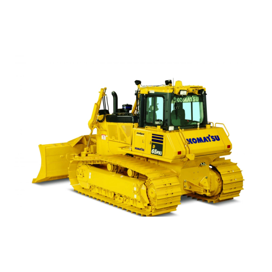
D65EXi
D65PXi
BULLDOZER
SERIAL NUMBER
D65EXi-18 - 90023
D65PXi-18 - 90023
WARNING
Unsafe use of this machine may cause serious injury or
death. Operators and maintenance personnel must read
this manual before operating or maintaining this
machine. This manual should be kept inside the cab for
reference and periodically reviewed by all personnel who
will come into contact with the machine.
-18
-18
and up
and up
ORIGINAL INSTRUCTIONS
EENAM03390
Advertisement
Chapters
Table of Contents


Need help?
Do you have a question about the D65EXi-18 and is the answer not in the manual?
Questions and answers