Table of Contents
Advertisement
Quick Links
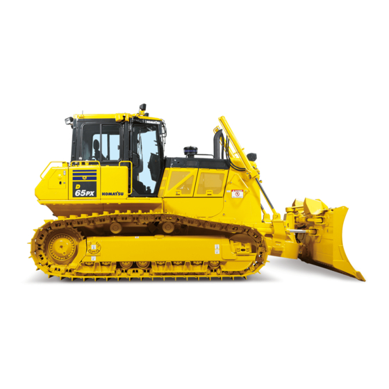
BULLDOZER
Unsafe use of this machine may cause serious injury or
death. Operators and maintenance personnel must read
this manual before operating or maintaining this machine.
This manual should be kept near the machine for
reference and periodically reviewed by all personnel who
will come into contact with it.
Komatsu has Operation & Maintenance Manuals
written in some other languages. If a foreign language
manual is necessary, contact your local distributor for
availability.
D65EX
D65PX
D65WX
SERIAL NUMBERS
WARNING
NOTICE
TEN00653-01
-18
-18
-18
90001
and up
Advertisement
Chapters
Table of Contents


Need help?
Do you have a question about the D65EX-18 and is the answer not in the manual?
Questions and answers