Table of Contents
Advertisement
Quick Links
Operation & Maintenance
Manual
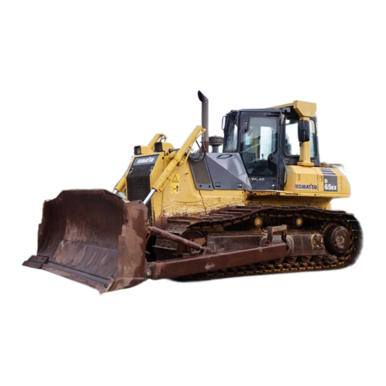
D65EX
D65PX
D65WX
BULLDOZER
SERIAL NUMBERS
This material is proprietary to Komatsu America Corp. and is not to be reproduced, used, or disclosed except in
accordance with written authorization from Komatsu America Corp.
It is our policy to improve our products whenever it is possible and practical to do so. We reserve the right to make
changes or improvements at any time without incurring any obligation to install such changes on products sold
previously.
Due to this continuous program of research and development, revisions may be made to this publication. It is
recommended that customers contact their distributor for information on the latest revision.
December 2004
-15
-15
-15
D65EX-15
D65PX-15
D65WX-15 67001
Copyright 2004 Komatsu
Printed in U.S.A.
Komatsu America Corp.
TEN00013-00
(Replaces SEAM049901T)
67001
and up
67001
and up
and up
Advertisement
Chapters
Table of Contents
Troubleshooting

Related Manuals for Komatsu GALEO D65EX-15


Summary of Contents for Komatsu GALEO D65EX-15
- Page 1 D65WX-15 67001 and up This material is proprietary to Komatsu America Corp. and is not to be reproduced, used, or disclosed except in accordance with written authorization from Komatsu America Corp. It is our policy to improve our products whenever it is possible and practical to do so. We reserve the right to make changes or improvements at any time without incurring any obligation to install such changes on products sold previously.
- Page 2 1 - 1...
-
Page 3: Foreword
Keep this manual at the storage location for the operation and maintenance manual given below, and have all personnel read it periodically. If this manual has been lost or has become dirty and cannot be read, request a replacement manual immediately from Komatsu or your Komatsu distributor. - Page 4 FOREWORD FOREWORD FOREWORD FOREWORD If machine is not equipped with cab. Rear face of floor 1 - 3...
- Page 5 FOREWORD FOREWORD 1 - 4...
- Page 6 FOREWORD FOREWORD 1 - 5...
- Page 7 FOREWORD SAFETY INFORMATION SAFETY INFORMATION To enable you to use this machine safely, safety precautions and labels are given in this manual and affixed to the machine to give explanations of situations involving potential hazards and of the methods of avoiding such situations.
- Page 8 Continuing improvements in the design of this machine can lead to changes in detail which may not be reflected in this manual. Consult Komatsu or your Komatsu distributor for the latest available information of your machine or for questions regarding information in this manual.
-
Page 9: Introduction
FOREWORD INTRODUCTION INTRODUCTION This Komatsu machine is designed to be used mainly for the following work: Dozing Smoothing Cutting into hard or frozen ground or ditching Felling trees, removing stumps See the section "WORK POSSIBLE USING BULLDOZER (PAGE 3-103)" for further details. -
Page 10: Necessary Information
FOREWORD NECESSARY INFORMATION NECESSARY INFORMATION When requesting service or ordering replacement parts, please inform your Komatsu distributor of the following items. PRODUCT IDENTIFICATION NUMBER (PIN)/MACHINE SERIAL NO. PLATE This is at the front bottom right of the operator's seat. The design of the nameplate differs according to the territory. -
Page 11: Position Of Service Meter
FOREWORD NECESSARY INFORMATION POSITION OF SERVICE METER The service meter is provided at the lower part of the monitor panel. TABLE OF ENTER SERIAL NO. AND DISTRIBUTOR Machine serial No. Engine serial No. Product identification number (PIN) Distributor name Address Service Personnel Phone/Fax 1 - 10... -
Page 12: Table Of Contents
FOREWORD CONTENTS CONTENTS FOREWORD FOREWORD SAFETY INFORMATION INTRODUCTION FRONT/REAR, LEFT/RIGHT DIRECTIONS OF MACHINE NECESSARY INFORMATION PRODUCT IDENTIFICATION NUMBER (PIN)/MACHINE SERIAL NO. PLATE ENGINE SERIAL NO. PLATE POSITION OF SERVICE METER 1- 10 TABLE OF ENTER SERIAL NO. AND DISTRIBUTOR 1- 10 SAFETY SAFETY SAFETY LABELS... - Page 13 4- 11 USE OF FUEL, COOLANT AND LUBRICANTS ACCORDING TO AMBIENT TEMPERATURE 4- 12 RECOMMENDED BRANDS, RECOMMENDED QUALITY FOR PRODUCTS OTHER THAN KOMATSU GENUINE OIL 4- 13 STANDARD TIGHTENING TORQUES FOR BOLTS AND NUTS 4- 14 TORQUE LIST 4- 14...
- Page 14 FOREWORD CONTENTS MAINTENANCE SCHEDULE CHART 4- 17 ADJUST INJECTOR 4- 19 SERVICE PROCEDURE 4- 20 WHEN REQUIRED 4- 20 CHECK BEFORE STARTING 4- 40 EVERY 50 HOURS SERVICE 4- 41 EVERY 250 HOURS SERVICE 4- 42 EVERY 500 HOURS SERVICE 4- 52 EVERY 1000 HOURS SERVICE 4- 56...
- Page 16 2 - 1...
-
Page 17: Safety
SAFETY SAFETY SAFETY SAFETY LABELS POSITIONS OF SAFETY PICTOGRAMS SAFETY LABELS GENERAL PRECAUTIONS Safety rules If abnormalities are found Clothing and personal protective items Fire extinguisher and first aid kit Safety features Keep machine clean 2- 10 Inside operator's compartment 2- 10 Always apply lock when leaving operator's seat 2- 10... - Page 18 SAFETY SAFETY PRECAUTIONS FOR OPERATION 2- 17 STARTING ENGINE 2- 17 Checks before starting engine 2- 17 Precautions when starting 2- 17 Precautions in cold areas 2- 17 OPERATION 2- 19 Checks before operation 2- 19 Precautions for moving machine forward or in reverse 2- 19 Precautions when traveling 2- 19...
-
Page 19: Safety Labels
If the labels are damaged, lost, or cannot be read properly, replace them with new ones. For details of the part numbers for the labels, see this manual or the actual label, and place an order with Komatsu distributor. POSITIONS OF SAFETY PICTOGRAMS... -
Page 20: Safety Labels
SAFETY SAFETY LABELS SAFETY LABELS (1) Caution before operating or maintaining machine (09651-03001) (2) Caution before moving in reverse (09802-13000) (3) Caution for leaving operator's seat (09654-33001) 2 - 5... - Page 21 SAFETY SAFETY SAFETY LABELS SAFETY LABELS (4) Caution for high-temperature cooling water (09668-03001) (5) Caution for high-temperature oil (09653-03001) (6) Caution for accumulator (09659-53000) 2 - 6...
- Page 22 SAFETY SAFETY SAFETY LABELS SAFETY LABELS (7) Caution for adjusting track tension (09657-03003) The safety label is attached to the rear side of the track adjustment window cover. (8) Caution for battery cable (09808-03000) (9) Caution for engine running (09667-03001) (10) Caution for approach when machine moving (09812-13000) 2 - 7...
- Page 23 SAFETY SAFETY SAFETY LABELS SAFETY LABELS (11) Jump start prohibited (09842-A0481) (12) Precautions when handling battery (13) Caution for ROPS (09620-B2000) (14) Caution for FOPS (09620-C2000) 2 - 8...
-
Page 24: General Precautions
SAFETY GENERAL PRECAUTIONS GENERAL PRECAUTIONS SAFETY RULES Only trained and authorized personnel can operate and maintain the machine. Follow all safety rules, precautions and instructions when operating or performing maintenance on the machine. If you are under the influence of alcohol or medication, your ability to safely operate or repair your machine may be severly impaired putting yourself and everyone else on your jobsite in danger. -
Page 25: Keep Machine Clean
SAFETY GENERAL PRECAUTIONS KEEP MACHINE CLEAN If water gets into the electrical system, there is a hazard that it will cause malfunctions or misoperation. Do not use water or steam to wash the electrical system (sensors, connectors). If inspection and maintenance is carried out when the machine is still dirty with mud or oil, there is a hazard that you will slip and fall, or that dirt or mud will get into your eyes. -
Page 26: Handrails And Steps
SAFETY GENERAL PRECAUTIONS HANDRAILS AND STEPS To prevent personal injury caused by slipping or falling off the machine, always do as follows. Use the handrails and steps marked by arrows in the diagram on the right when getting on or off the machine. To ensure safety, always face the machine and maintain three-point contact (both feet and one hand, or both hands and one foot) with the handrails and steps (including the track shoe) -
Page 27: Prevention Of Burns
SAFETY GENERAL PRECAUTIONS PREVENTION OF BURNS Hot coolant To prevent burns from hot water or steam spurting out when checking or draining the coolant, wait for the water to cool to a temperature where it is possible to touch the radiator cap by hand before starting the operation. -
Page 28: Action If Fire Occurs
If ROPS is deformed by falling objects or by rolling over, its strength lowers and its design functions cannot be maintained. In this case, be sure to ask your Komatsu distributor about repair method. Even if ROPS is installed, it does not work normally, if your seat belt is not fastened. Be sure to fasten your seat belt when operating machine. -
Page 29: Unauthorized Modification
Any modification made without authorization from Komatsu can create hazards. Before making a modification, consult your Komatsu distributor. Komatsu will not be responsible for any injuries, accidents, product failures or other property damages resulting from modifications made without authorization from Komatsu. -
Page 30: Ensure Good Visibility
SAFETY SAFETY SAFETY GENERAL PRECAUTIONS GENERAL PRECAUTIONS GENERAL PRECAUTIONS Even going close to high-voltage cables can cause electric Voltage of Cables Safety Distance shock, which may cause serious burns or even death. Always 100 V - 200 V Over 2 m (7 ft) maintain a safe distance (see the table on the right) between the 6,600 V Over 2 m (7 ft) -
Page 31: Be Careful About Asbestos Dust
Do not allow other persons to approach during the operation. Always observe the rules and regulations for the work site and environmental standards. This machine does not use asbestos, but there is a danger that imitation parts may contain asbestos, so always use genuine Komatsu parts. 2 - 16... -
Page 32: Precautions For Operation
SAFETY PRECAUTIONS FOR OPERATION PRECAUTIONS FOR OPERATION STARTING ENGINE If there is a warning tag hanging from the work equipment control lever, do not start the engine or touch the levers . CHECKS BEFORE STARTING ENGINE Carry out the following checks before starting the engine at the beginning of the day's work. Remove all dirt from the surface of the window glass to ensure a good view. - Page 33 SAFETY PRECAUTIONS FOR OPERATION If the battery electrolyte is frozen, do not charge the battery or start the engine with a different power source. There is a hazard that this will ignite the battery and cause the battery to explode. Before charging or starting the engine with a different power source, melt the battery electrolyte and check that there is no leakage of electrolyte before starting.
-
Page 34: Operation
SAFETY PRECAUTIONS FOR OPERATION OPERATION CHECKS BEFORE OPERATION When carrying out the checks, move the machine to a wide area where there are no obstructions, and operate slowly. Do not allow anyone near the machine. Always fasten your seat belt. Check the operation of travel, steering and brake systems, and work equipment control system. -
Page 35: Traveling On Slopes
SAFETY SAFETY PRECAUTIONS FOR OPERATION PRECAUTIONS FOR OPERATION Avoid traveling over obstacles when possible. If the machine has to travel over an obstacle, keep the work equipment close to the ground and travel at low speed. Never travel over obstacles which make the machine tilt strongly to one side. When traveling or carrying out operations, always keep a safe distance from people, structures, or other machines to avoid coming into contact with them. -
Page 36: Parking Machine
SAFETY PRECAUTIONS FOR OPERATION If the machine enters deep snow, there is a hazard that it may tip over or become buried in the snow. Be careful not to leave the road shoulder or to get trapped in a snow drift. When clearing snow, the road shoulder and objects placed beside the road are buried in the snow and cannot be seen. -
Page 37: Transportation
PRECAUTIONS FOR OPERATION TRANSPORTATION The machine can be divided into parts for transportation, so when transportating the machine, please contact your Komatsu distributor to have the work carried out. LOADING AND UNLOADING When loading or unloading the machine, mistaken operation may bring the hazard of the machine tipping over or falling, so particular care is necessary. -
Page 38: Battery
SAFETY PRECAUTIONS FOR OPERATION BATTERY BATTERY HAZARD PREVENTION Battery electrolyte contains sulphuric acid, and batteries generate flammable hydrogen gas, which may explode. Mistaken handling can lead to serious injury or fire. For this reason, always observe the following precautions. Do not use or charge the battery if the battery electrolyte level is below the LOWER LEVEL line. This may cause an explosion. -
Page 39: Starting With Booster Cable
SAFETY PRECAUTIONS FOR OPERATION STARTING WITH BOOSTER CABLE If any mistake is made in the method of connecting the booster cables, it may cause the battery to explode, so always do as follows. When starting with a booster cable, carry out the starting operation with two workers (one worker sitting in the operator's seat and the other working with the battery). -
Page 40: Towing
SAFETY PRECAUTIONS FOR OPERATION TOWING WHEN TOWING Serious injury or death could result if a disabled machine is towed incorrectly or if there is a mistake in the selection or inspection of the wire rope. For towing method, see section "MACHINE TOWING METHOD (PAGE 3-127)". Always wear leather gloves when handling wire rope. -
Page 41: Precautions For Maintenance
SAFETY PRECAUTIONS FOR MAINTENANCE PRECAUTIONS FOR MAINTENANCE WARNING TAG Always attach the "DO NOT OPERATE" warning tag to the work equipment control lever in the operator's cab to alert others that you are performing service or maintenance on the machine. Attach additional warning tags around the machine if necessary. -
Page 42: Two Workers For Maintenance When Engine Is Running
SAFETY SAFETY PRECAUTIONS FOR MAINTENANCE PRECAUTIONS FOR MAINTENANCE Set work equipment lock lever (1) and parking brake lever (2) to the LOCK position. Put blocks under the track to prevent the machine from moving. TWO WORKERS FOR MAINTENANCE WHEN ENGINE IS RUNNING To prevent injury, do not carry out maintenance with the engine running. -
Page 43: Proper Tools
Do not make holes in it, weld it, or use a cutting torch. Do not hit or roll the accumulator, or subject it to any impact. When disposing of the accumulator, the gas must be released. Please contact your Komatsu distributor to have this work performed. NO UNAUTHORIZED PERSONNEL INTO AREA Only authorized personnel can service and repair the machine. -
Page 44: Work Under The Machine
SAFETY PRECAUTIONS FOR MAINTENANCE WORK UNDER THE MACHINE If it is necessary to go under the work equipment or the machine to carry out service and maintenance, support the work equipment and machine securely with blocks and stands strong enough to support the weight of the work equipment and machine. -
Page 45: Precautions When Using High-Pressure Grease To Adjust Track Tension
If it is disassembled by mistake, the spring will fly out and cause serious injury. When it becomes necessary to disassemble it, ask your Komatsu distributor to do the work. PRECAUTION WITH HIGH-PRESSURE OIL The hydraulic system is always under internal pressure. -
Page 46: Handling High-Pressure Hoses
If any loose bolts are found, stop work and tighten to the specified torque. If any damaged hoses are found, stop operations immediately and contact your Komatsu distributor. Replace the hose if any of the following problems are found. -
Page 47: Periodic Replacement Of Safety Critical Parts
SAFETY PRECAUTIONS FOR MAINTENANCE PERIODIC REPLACEMENT OF SAFETY CRITICAL PARTS In order for the machine to be operated safety for a long time, it is necessary to add oil and to carry out service and maintenance at periodic intervals. In order to further increase safety, components with a strong relationship to safety, such as hoses and seat belts, must be replaced at periodic intervals. - Page 48 3 - 1...
-
Page 49: General View
OPERATION GENERAL VIEW GENERAL VIEW GENERAL VIEW OF MACHINE Machine equipped with cab Machine equipped with canopy Blade Track shoe Tilt cylinder Sprocket Lift cylinder Track frame Push arm ROPS canopy (10) Idler 3 - 2... -
Page 50: General View Of Controls And Gauges
OPERATION GENERAL VIEW GENERAL VIEW OF CONTROLS AND GAUGES Machine equipped with cab Parking brake lever (12) Fan rotation selector switch Work equipment lock lever (13) Starting switch Cigarette lighter (14) Information switch Fuel control dial (15) Buzzer cancel switch Joystick (Steering, directional and (16) Brake pedal... - Page 51 OPERATION GENERAL VIEW Machine equipped with canopy Parking brake lever (10) Fan rotation selector switch Work equipment lock lever (11) Information switch (12) Buzzer cancel switch Fuel control dial Joystick (Steering, directional and (13) Starting switch gear shift lever) (14) Brake pedal Auto shift down switch (15)
- Page 52 OPERATION GENERAL VIEW MONITOR PANEL Display panel A (Speed range, Engine speed) Filter, oil change interval lamp Power train oil temperature gauge (10) Warning lamp Engine coolant temperature gauge (11) Engine coolant temperature caution lamp Hydraulic oil temperature gauge (12) Maintenance caution lamp Fuel gauge (13)
-
Page 53: Explanation Of Components
OPERATION EXPLANATION OF COMPONENTS EXPLANATION OF COMPONENTS The following is an explanation of devices needed for operating the machine. To perform suitable operations correctly and safely, it is important to completely understand methods of operating the equipment, and the meanings of the displays. FRONT PANEL Emergency caution group Lamp... - Page 54 Stop the engine, then turn the starting switch to the ON position and check that the lamps light up for approx. 2 seconds. If they do not light up, please ask your Komatsu distributor to carry out inspection. The monitor check cannot be carried out until at least 5 seconds has passed after the engine was stopped.
- Page 55 OPERATION EXPLANATION OF COMPONENTS EMERGENCY CAUTION ITEMS CAUTION If any of the caution lamps begins to flash, stop the engine or reduce the engine speed to low idling immediately and check the trouble spot for necessary actions. These items must be monitored when the engine is running. If there is any problem, the caution lamp for the location of the problem and warning lamp (A) flash, and the alarm buzzer sounds intermittently.
- Page 56 OPERATION EXPLANATION OF COMPONENTS ENGINE OIL PRESSURE CAUTION LAMP This lamp (1) indicates a low engine oil pressure. If the monitor lamp flashes, stop the engine and check it immediately. REMARK The alarm buzzer sounds, when the starting switch is turned to ON immediately after the engine oil has been changed.
- Page 57 OPERATION EXPLANATION OF COMPONENTS CAUTION ITEMS CAUTION If these caution lamps item flash, check and repair the appropriate location as soon as possible. These are items which need to be observed when the engine is running. If any problem occurs, the item needing immediate repair is displayed.
- Page 58 OPERATION EXPLANATION OF COMPONENTS MAINTENANCE CAUTION LAMP This lamp (2) lights up for approx. 30 seconds after the starting switch is turned to the ON position if the filter or oil replacement interval has been reached. After replacing the indicated filter or oil displayed on display panel B (multi-information), reset the interval.
- Page 59 OPERATION EXPLANATION OF COMPONENTS METER GROUP Engine coolant temperature gauge Engine preheating pilot lamp Power train oil temperature gauge Display panel A Hydraulic oil temperature gauge (Speed range display, Engine speed) Fuel gauge Display panel B (multi-information) ENGINE COOLANT TEMPERATURE GAUGE NOTICE If the coolant temperature gauge often enters red range (C), check the radiator for clogging.
- Page 60 OPERATION EXPLANATION OF COMPONENTS POWER TRAIN OIL TEMPERATURE GAUGE NOTICE If the power train oil temperature gauge often enters the red range (C), we recommend you to lower the travel speed one range (for example, F2 → F1) to reduce the load on the power train when operating. Gauge (2) indicates the torque converter outlet oil temperature.
- Page 61 OPERATION EXPLANATION OF COMPONENTS ENGINE PRE-HEATING PILOT LAMP This lamp (5) indicates that the engine is being preheated with an electric heater in cold weather. When the engine starting switch is turned to the ON position, the engine controller detects the engine coolant temperature and automatically starts to preheat the engine at low temperature.
- Page 62 OPERATION EXPLANATION OF COMPONENTS DISPLAY PANEL B (multi-information) The top and bottom lines in display panel B (multi-information) display information related to the condition of the machine. The content of the display is divided into "OPERATING MODE" and "MAINTENANCE MODE". Use the buzzer cancel switch to switch between the operating mode and maintenance mode.
- Page 63 OPERATION OPERATION EXPLANATION OF COMPONENTS EXPLANATION OF COMPONENTS Maintenance mode This displays various types of information related to maintenance of the machine. For details, see "METHOD OF USING MAINTENANCE MODE (PAGE 3-24)". 3 - 16...
- Page 64 OPERATION EXPLANATION OF COMPONENTS LAMPS Warning lamp Fan operation confirmation lamp Filter, oil change interval lamp WARNING LAMP (Red) NOTICE If alarm buzzer sounds, stop work immediately and perform inspection and maintenance of the appropriate point. This lamp (1) flashes when the caution lamp flashes and when an action code is displayed on display panel B (multi-information).
- Page 65 OPERATION EXPLANATION OF COMPONENTS FILTER/OIL REPLACEMENT INTERVAL LAMP (Yellow) If it is time to replace a filter or change the oil, this lamp (2) lights up or flashes for approx. 30 seconds after the starting switch is turned REMARK This lamp (2) lights up if there is less than 30 hours remaining until replacement, and flashes when the replacement interval has passed.
-
Page 66: Switches
OPERATION EXPLANATION OF COMPONENTS SWITCHES Machine equipped with cab Machine equipped with canopy Starting switch Rear lamp switch Auto shift down switch Fan rotation selector switch Preset mode switch Information switch Head lamp switch Buzzer cancel switch 3 - 19... - Page 67 OPERATION EXPLANATION OF COMPONENTS STARTING SWITCH This switch (1) is used to start or stop the engine. OFF position At this position, the starting switch key can be inserted and removed. When the switch is turned to this position, all the electric circuits are turned off and the engine stops.
- Page 68 OPERATION EXPLANATION OF COMPONENTS HEAD LAMP SWITCH This switch (4) lights up when the front lamp, and panel lamp light (OFF) position: Lights out (ON) position: Lights on REAR LAMP SWITCH This switch (5) lights up the rear lamps. (OFF) position: Lights out (ON) position: Lights on 3 - 21...
- Page 69 OPERATION EXPLANATION OF COMPONENTS FAN ROTATION SELECTOR SWITCH This switch (6) is used to switch the direction of rotation of the cooling fan. position : Normal rotation Normally use this position. The air is pushed out to the front through the radiator mask.
- Page 70 OPERATION EXPLANATION OF COMPONENTS INFORMATION SWITCH This switch (7) is used to operate display panel B (multi-information). When the switch is released, it returns automatically to the center position. When display panel B (multi-information) is in the operation mode turn the switch to < or > to switch the display to service meter or engine speed.
- Page 71 OPERATION EXPLANATION OF COMPONENTS METHOD OF USING MAINTENANCE MODE To switch from the operation mode to the maintenance mode, turn the buzzer cancel switch to the position and hold it there for at least 2.5 seconds. The screen will switch to the maintenance mode.
- Page 72 OPERATION EXPLANATION OF COMPONENTS METHOD OF SELECTING EACH MODE 3 - 25...
- Page 73 This function is only a guideline. If dirty oil or filters are found during daily maintenance, replace them immediately. If the controllers or monitor panel are replaced, the timer for this function will not work properly. Contact your Komatsu distributor for replacement.
- Page 74 OPERATION OPERATION EXPLANATION OF COMPONENTS EXPLANATION OF COMPONENTS REMARK To return to the maintenance mode, operate the buzzer cancel switch to 3 - 27...
- Page 75 OPERATION EXPLANATION OF COMPONENTS METHOD OF USING PM CLINIC AUXILIARY MODE CAUTION When moving the work equipment or setting the transmission to the travel position for carrying out measurements, check carefully that the situation is safe. The PM clinic auxiliary mode displays the engine speed or hydraulic pressure on display panel B (multi-information). Display panel B displays the item on the top line (1) and the measured value on the bottom line (2).
- Page 76 When any disconnection or short circuit in any sensor is detected, the location and fault code are displayed by a 6-digit code on display panel B (multi-information). When contacting your Komatsu distributor, inform your distributor of the code at the same time.
- Page 77 OPERATION EXPLANATION OF COMPONENTS METHOD OF USING USER ADJUST MODE With the user adjust mode, the brightness of the panel screen backlighting and the contrast of the liquid crystal panel can be changed. 1. Adjusting backlighting of liquid crystal display 1) The diagram on the right is the mode for adjusting the brightness of the backlighting of the liquid crystal panel.
- Page 78 OPERATION EXPLANATION OF COMPONENTS 2. Adjusting backlighting of display panel B (multi-information) 1) The diagram on the right is the mode for adjusting the brightness of the backlighting of the display panel B (multi-information). On the screen, operate the buzzer cancel switch to switch to the screen for adjusting the brightness.
- Page 79 OPERATION EXPLANATION OF COMPONENTS 3. Adjusting contrast of liquid crystal display panel B (multi-information) 1) The diagram on the right is the mode for adjusting the contrast liquid crystal display panel (multi-information). On this screen, operate the buzzer cancel switch to to switch to the screen to adjust the contrast.
- Page 80 OPERATION EXPLANATION OF COMPONENTS SWITCHES Machine equipped with cab Machine equipped with canopy Fuel control dial Wiper switch Horn switch Cigarette lighter Room lamp switch Accessory socket 3 - 33...
- Page 81 OPERATION EXPLANATION OF COMPONENTS FUEL CONTROL DIAL Dial (1) is used to control the engine speed and output. (a) Low idling position: Turn fully to the left (b) High idling position: Turn fully to the right HORN SWITCH The horn sounds when the button (2) at the rear of the blade control lever at the right side of the operator's seat is pressed.
- Page 82 OPERATION EXPLANATION OF COMPONENTS WIPER SWITCH This (4) activates the wipers. The wiper switches are as follows: (LH) Left door (FF) Front window (RH) Right door (RR) Rear window (INT) Wiper intermittent operation switch This is also used as the window washer switch. The switch is operated as follows.
- Page 83 OPERATION OPERATION EXPLANATION OF COMPONENTS EXPLANATION OF COMPONENTS Wiper intermittent operation switch If the wiper is operated with the switch at the ON position, the wiper will move once every four seconds. REMARK When the wiper intermittent operation switch is ON, if the wiper switch for each window is turned ON, the wiper will move intermittently.
-
Page 84: Control Levers And Pedals
OPERATION EXPLANATION OF COMPONENTS CONTROL LEVERS AND PEDALS Work equipment lock lever Brake pedal Parking brake lever Deceleration pedal Joystick (steering, directional and Blade control lever gear shift lever) WORK EQUIPMENT LOCK LEVER WARNING When leaving the operator's compartment, set the work equipment lock lever securely to the LOCK position. If the work equipment lock lever is not at the LOCK position and the control levers are touched by mistake, it may lead to serious personal injury. - Page 85 OPERATION EXPLANATION OF COMPONENTS PARKING BRAKE LEVER WARNING When parking the machine, always set the parking brake lever in the LOCK position. If the parking brake lever is operated, the brake is applied, even when the machine is traveling. The machine will suddenly stop, so this is dangerous. For this reason, do not operate the parking brake lever when the machine is moving, except in emergencies.
- Page 86 OPERATION OPERATION EXPLANATION OF COMPONENTS EXPLANATION OF COMPONENTS Gear shifting When switch (c) or switch (d) is pushed, the transmission speed will change. UP switch (c): Each time the switch is pressed, the transmission will up shift one speed. DOWN switch (d): Each time the switch is pressed, the transmission will down shift one speed.
- Page 87 OPERATION EXPLANATION OF COMPONENTS BRAKE PEDAL WARNING Do not place your foot on this pedal unnecessarily. Depress the pedal (4) to apply the right and left brakes. DECELERATOR PEDAL WARNING Do not place your foot on this pedal unnecessarily. When passing over the top of a hill or when a load is dumped over a cliff, the load is suddenly reduced, so there is danger that the travel speed will also increase suddenly.
- Page 88 OPERATION EXPLANATION OF COMPONENTS BLADE CONTROL LEVER POWER TILTDOZER This lever (6) is used to lift or tilt the blade. Lifting control (a) RAISE: (b) HOLD: Blade is stopped and held in this position. (c) LOWER: (d) FLOAT: Blade will move freely according to external force. REMARK If the lever is in the FLOAT position, even when it is released, it does not return to the HOLD position, so return it by hand.
- Page 89 OPERATION EXPLANATION OF COMPONENTS POWERTILT POWER PITCHDOZER This lever (6) is used to lift or tilt and pitch the blade. Lifting control (a) RAISE: (b) HOLD: Blade is stopped and held in this position. (c) LOWER: (d) FLOAT: Blade will move freely according to external force. REMARK If the lever is in the FLOAT position, even when it is released, it does not return to the HOLD position, so return it by hand.
- Page 90 OPERATION OPERATION EXPLANATION OF COMPONENTS EXPLANATION OF COMPONENTS Pitch control First set the lever to the neutral position, then keep switch (A) in the center of the knob pushed down and carry out the tilt operation to change the cutting angle of the blade. (b) HOLD: Blade is stopped and held in this position.
- Page 91 OPERATION EXPLANATION OF COMPONENTS ANGLE DOZER (D65EX,D65PX) This lever (6) is used to lift the blade. Lifting control (a) RAISE: (b) HOLD: Blade is stopped and held in this position. (c) LOWER: (d) FLOAT: Blade will move freely according to external force. REMARK If the lever is in the FLOAT position, even when it is released, it does not return to the HOLD position, so return it by hand.
-
Page 92: Circuit Breaker
OPERATION EXPLANATION OF COMPONENTS CIRCUIT BREAKER NOTICE When resetting the circuit breaker, always turn off the power first (turn the starting switch OFF). If the reset button for the circuit breaker comes out immediately when it is pushed in, it is necessary to carry out an inspection of the electrical circuit. -
Page 93: Fuse
OPERATION EXPLANATION OF COMPONENTS FUSE NOTICE Before replacing a fuse, be sure to turn starting switch to the OFF position. The fuses protect the electrical equipment and wiring from burning out. If the fuse becomes corroded, or white powder can be seen, or the fuse is loose in the fuse holder, replace the fuse. Replace the fuse with another of the same capacity. -
Page 94: Fusible Link
OPERATION EXPLANATION OF COMPONENTS Fuse box (B) Fuse Circuit capacity Monitor panel Fuel pump Air conditioner (if equipped) Backup alarm (if equipped) Body power source Fuse box (C) Fuse Circuit capacity Radio memory Radio,lamp,cigarette lighter Heated glass (EU specification) Rear wiper Front wiper Left and right door wiper FUSIBLE LINK... -
Page 95: Electric Power Take-Out Adapter
OPERATION OPERATION EXPLANATION OF COMPONENTS EXPLANATION OF COMPONENTS Fusible link (2) Open the engine side cover on the right side of the machine. Fusible link (2) can be seen under the window washer tank. Capacity: 120 A ELECTRIC POWER TAKE-OUT ADAPTER MACHINE EQUIPPED WITH CAB NOTICE The power for the cigarette lighter is 24V. -
Page 96: Door - Open Lock
OPERATION EXPLANATION OF COMPONENTS DOOR - OPEN LOCK (Machines equipped with cab) Use this when your want to keep the door held open. 1. Push the door against the door catch (1). The door will be held by the door catch. 2. -
Page 97: Door Pocket
OPERATION EXPLANATION OF COMPONENTS DOOR POCKET (Machines equipped with cab) This is inside the left and right doors. Use it for storing the Operation and Maintenance Manual or other things. Do not put heavy tools or other heavy objects in it. If the pocket is dirty, turn 4 clips (1), then remove the pocket and rinse it. -
Page 98: Ashtray
OPERATION EXPLANATION OF COMPONENTS ASHTRAY This is on the left side of the operator's seat. Always make sure that you extinguish the cigarette before closing the lid. CUP HOLDER (If equipped) This is the place to put cans or cups. If drinks are put in places other than the cup holder, the can or cup will fall over and make the surrounding area or equipment dirty. -
Page 99: Car Stereo, Handling
OPERATION EXPLANATION OF COMPONENTS CAR STEREO, HANDLING (Machine equipped with cab) (If equipped) EXPLANATION OF COMPONENTS Power switch/volume Cassette door Auto-store/preset scan button Fast forward, rewind buttons Bass control knob (10) Preset buttons Treble control knob (11) Metal tape button Loudness button (12) Manual tuning buttons... - Page 100 OPERATION EXPLANATION OF COMPONENTS POWER SWITCH/VOLUME Turn this knob (1) to the right until it clicks to turn the power on. Turn it further to increase the volume. AUTO-STORE/PRESET SCAN BUTTON Use this button (2) to actuate the preset scan and auto-store functions.
- Page 101 OPERATION EXPLANATION OF COMPONENTS TREBLE CONTROL KNOB Turn this button (4) to the left to reduce the low tones; turn it to the right to emphasize the high tones. Direction (a): High tone reduced Direction (b): High tone emphasized LOUDNESS BUTTON This button (5) is used when playing at low volume.
- Page 102 OPERATION EXPLANATION OF COMPONENTS TAPE EJECT BUTTON This button (7) is used to stop the tape and to eject the cassette. When this button is pressed, the tape is ejected and the radio plays. CASSETTE DOOR Set the cassette with the exposed portion of the tape on the right side and insert it through the cassette door (8).
- Page 103 OPERATION EXPLANATION OF COMPONENTS METAL TAPE BUTTON (used also for preset button No. 5) This button (11) is used when playing a metal or chrome tape. This button is also used for preset button No. 5. When it is pressed, "MTL"...
- Page 104 OPERATION EXPLANATION OF COMPONENTS METHOD OF OPERATION METHOD OF SETTING PRESET BUTTONS It is possible to preset 6 MW (AM) stations and 12 FM stations (FM1: 6 stations, FM2: 6 stations). REMARK If you are playing the cassette, press the tape eject button to stop the tape. METHOD OF AUTO PRESET 1.
- Page 105 OPERATION EXPLANATION OF COMPONENTS LISTENING TO RADIO 1. Turn the starting switch ON, then turn power switch (1) ON. 2. Use band selector button (2) to select MW (AM), FM1 or FM2. 3. Select the station with the preset buttons (3). REMARK In case you do not promptly remember the number assigned to a certain preset station, press auto-store/preset scan button (4) for...
- Page 106 If the sound cannot be heard, nothing is displayed, or any other abnormality occurs, turn off the power switch and ask your Komatsu distributor to make repairs without delay. Stow the antenna when traveling in places with low overhead clearance.
-
Page 107: Air Conditioner, Handling
OPERATION EXPLANATION OF COMPONENTS AIR CONDITIONER, HANDLING (Machine equipped with cab) (If equipped) By taking fresh air into the cab through a filter, it is possible to raise the pressure inside the cab. This makes it possible to provide a pleasant working environment even on dusty jobsites. GENERAL LOCATIONS AND FUNCTION OF CONTROL PANEL Fan switch Fresh/recirc selector switch... - Page 108 OPERATION EXPLANATION OF COMPONENTS FRESH/RECIRC SELECTOR SWITCH This switch (3) is used to select between recirculation of the air inside the cab or intake of fresh air from outside. When the switch is pressed, indicator lamp (A) at the top of the switch lights up.
- Page 109 OPERATION EXPLANATION OF COMPONENTS METHOD OF OPERATION Switch Air conditioner Temperature FRESH/RECIRC Fan switch switch control switch selector switch Condition of use Rapid All blue RECIRC Cooling More than half Normal HI - LO FRESH are blue Dehumidifying, More than half HI - LO FRESH heating...
- Page 110 OPERATION EXPLANATION OF COMPONENTS PRECAUTION WHEN USING AIR CONDITIONER PRECAUTION WHEN USING COOLING OPERATION If you smoke when using the air conditioner, your eyes may start to itch or burn. Ventilate the cab ever so often to remove the smoke. When using the air conditioner for a long period of time, carry out ventilation process at least once every hour.
- Page 111 OPERATION EXPLANATION OF COMPONENTS CLEANING AIR FILTER If the air filter for the FRESH or RECIRC air intake becomes clogged, the cooling or heating capacity will drop. To prevent this, clean the air filter with compressed air once a week. For details of the cleaning method, see "WHEN REQUIRED (PAGE 4-20)".
-
Page 112: Accumulator, Handling
Do not make holes in it or weld it. Do not hit it, roll it, or subject it to any impact. When disposing of the accumulator, the gas must be released. Please contact your Komatsu distributor to have this work carried out. -
Page 113: Operation
Check carefully, and if any abnormality is found, repair it or contact your Komatsu distributor. Do not get on or off the machine from the rear. Using this position is dangerous because it is easy to slip and you cannot be seen from the operator's compartment. - Page 114 OPERATION OPERATION 8. Check for damage to seat belt and mounting clamps (if equipped) Check that there is no abnormality in the seat belt or mounting clamps. If there is any damage, replace with new parts. 3 - 67...
- Page 115 OPERATION OPERATION CHECK BEFORE STARTING Always check the items in this section before starting the engine each day. CHECK OIL LEVEL IN ENGINE OIL PAN, ADD OIL WARNING Parts and oil are at high temperature immediately after the engine is stopped and may cause serious burns. Wait for the oil temperature to go down before performing this operation.
- Page 116 OPERATION OPERATION CHECK DUST INDICATOR 1. Open engine side cover on the left side of machine. 2. Check if a yellow piston in the display of dust indicator (1) has moved into the red area (7.5 kPa). 3. If the yellow piston has already moved into the red area (7.5 kPa), either clean the filter element or replace it with new one immediately.
- Page 117 OPERATION OPERATION CHECK COOLANT LEVEL, ADD COOLANT WARNING Do not open the radiator cap unless necessary. Wait for the engine to cool down before checking the coolant in the sub-tank. Immediately after the engine is stopped, the coolant is at a high temperature and the radiator is under high internal pressure. If the cap is removed to check the coolant level in this condition, there is a hazard of burns.
- Page 118 If the fuses frequently blow or if there are traces of short circuits in the electrical wiring, locate the cause and immediately perform repairs, or contact your Komatsu distributor for repairs. Keep the top surface of the battery clean and check the breather hole in the battery cap. If it is clogged with dirt or dust, wash the battery cap to clean the breather hole.
- Page 119 90 mm (2.8 to 3.5 in). 3. When this value exceeds 91 mm (3.6 in), or the brake fails to work, please contact your Komatsu distributor for adjustment. CHECKING WITH MACHINE MONITOR 1. Turn starting switch (1) to the ON position.
- Page 120 OPERATION OPERATION CHECK FUEL LEVEL, ADD FUEL WARNING When adding fuel, never spill the fuel or let it overflow. It will cause fire. If any fuel has spilled, wipe it up completely. If fuel has spilled over soil or sand, remove that soil or sand. Fuel is highly flammable and dangerous.
- Page 121 Check that the head lamp, rear lamp, additional working lamp (if equipped), and instrument lamp light up normally and they are free from stain and damage. If the lamps do not light, check for a broken bulb or disconected wire, contact your Komatsu distributor for repairs. 1. Turn the starting switch to the ON position.
- Page 122 CHECK OF OPERATION OF BACKUP ALARM (If equipped) Check that the backup alarm sounds normally. If it does not, a defect or broken wire is suspected, ask your Komatsu distributor for possible repairs. 1. Turn the starting switch to the ON position.
- Page 123 OPERATION OPERATION ADJUSTMENT ADJUST OPERATOR'S SEAT WARNING When adjusting the position of the operator's seat, always set the work equipment lock lever to the LOCK position to prevent any accidental contact with the control levers. Always adjust the operator's seat before starting each operation or when the operators change shift. When adjusting the seat, put your back against the backrest and adjust to a position where the brake pedal can be fully depressed.
- Page 124 OPERATION OPERATION FASTENING AND REMOVING SEAT BELT (If equipped) WARNING Before fastening the seat belt, check that there is no problem in the securing brackets or belt. If there is any wear or damage, replace. Even if there appears to be no problem in the seat belt, replace the seat belt once every 3 years. The date of manufacture is woven on the reverse side of the belt.
- Page 125 OPERATION OPERATION ADJUST MIRROR (If equipped) Loosen nut (1) of the mirror and adjust the mirror to a position where it gives the best view from the operator's seat. In particular, be sure to adjust the mirror so that people at the rear left or right of the machine can be seen clearly.
- Page 126 OPERATION OPERATION ADJUST ARMREST The height of the armrest on the left and right sides of the operator's seat can be adjusted to 3 positions. After adjusting the operator's seat, adjust the armrest to a suitable height. ADJUST ARMREST (RIGHT) Armrest (1) on the right side of the operator's seat can be adjusted in 3 stages: up 30 mm (1.2 in), standard height (center), or down 25 mm (1.0 in).
- Page 127 OPERATION OPERATION OPERATION AND CHECK BEFORE STARTING ENGINE WARNING When starting the engine, check that the parking brake lever and work equipment lock lever are placed securely at the LOCK position. If the work equipment control lever is touched by accident when the engine is started, the work equipment may move unexpectedly and cause serious injury or damage.
- Page 128 OPERATION OPERATION OPERATION OPERATION 3. Check that the blade is lowered to the ground and that blade control lever (3) is in the HOLD position. 4. Check that the work equipment lock lever (4) is locked. 3 - 81...
-
Page 129: Starting Engine
OPERATION OPERATION STARTING ENGINE NORMAL STARTING WARNING Sit down in the operator's seat before starting the engine. Do not attempt to start the engine by short-circuiting the engine starting circuit. Such an act may cause serious bodily injury or fire. Check that there are no persons or obstacles in the surrounding area, then sound the horn and start the engine. - Page 130 OPERATION OPERATION OPERATION OPERATION 3. When the engine starts, release the key in starting switch (2). The key will return automatically to the ON position. 3 - 83...
- Page 131 OPERATION OPERATION STARTING IN COLD WEATHER WARNING Start the engine only after sitting down in the operator's seat. Do not attempt to start the engine by short-circuiting the engine starting circuit. Such an act may cause a serious bodily injury or fire.
- Page 132 OPERATION OPERATION OPERATION OPERATION 3. Check that engine pre-heating pilot lamp (3) on the monitor panel lights up. 4. Maintain the key in the on position until the preheating pilot lamp (3) goes off. 5. When engine pre-heating pilot lamp (3) goes off, turn the key of starting switch (2) to the START position to crank the engine.
- Page 133 OPERATION OPERATION 7. When the engine rotation stabilizes, return to the low idle (MIN) position of fuel control dial (1) and then carry out the warming-up operation. REMARK Regardless of the ambient temperature, if the key in starting switch (2) is turned from OFF position to left, preheating pilot lamp (3) will light up and preheating will start.
-
Page 134: Operations And Checks After Starting Engine
BREAKING IN THE NEW MACHINE CAUTION Your Komatsu machine has been thoroughly adjusted and tested before shipment. However, operating the machine under severe conditions at the beginning can adversely affect the performance and shorten the machine life. Be sure to break-in the machine for the initial 100 hours (as indicated by the service meter). - Page 135 (B). (A): White range (B): Green range (C): Red range 3. Check for abnormal exhaust gas color, noise, or vibration. If any abnormality is found, contact your Komatsu distributor. STARTING IN COLD WEATHER (Ambient temperature below 10°C (50°F)) NOTICE When the hydraulic oil is at a low temperature, do not carry out operations or move the levers suddenly.
- Page 136 If the oil temperature in the power train is not raised properly, it will take longer to accelerate to the maximum speed. 6. Check for abnormal exhaust gas color, noise, or vibration. If any abnormality is found, contact your Komatsu distributor.
-
Page 137: Stopping Engine
OPERATION OPERATION STOPPING ENGINE NOTICE If the engine is abruptly stopped before it has cooled down, engine life may be drastically shortened. Do not abruptly stop the engine except for an emergency. If the engine has overheated, do not stop it abruptly, run it at medium speed allowing the engine to gradually cool down, then stop it. -
Page 138: Machine Operation
OPERATION OPERATION MACHINE OPERATION MOVING MACHINE WARNING When moving the machine, check that the area around the machine is safe, and sound the horn before moving. Do not allow anyone to enter the area around the machine. There is a blind spot at the rear of the machine, so be particularly careful when traveling in reverse. - Page 139 (5) and allow the machine to move. REMARK For machines equipped with a backup alarm, check that the backup alarm sounds when joystick (6) is placed in REVERSE. If the alarm does not sound, please contact your Komatsu distributor. 3 - 92...
- Page 140 OPERATION OPERATION STOPPING MACHINE WARNING Avoid stopping suddenly. Give yourself ample room when stopping. 1. Depress brake pedal (1) to stop the machine. NOTICE If the brake is depressed when the engine speed or travel speed is high, the brake disc may make a slipping sound. Normally, depress decelerator pedal (2) to reduce the engine speed and travel speed before depressing the brake.
-
Page 141: Shifting Gears
OPERATION OPERATION SHIFTING GEARS The machine does not have to be stopped to shift gears. 1. Move steering, forward-reverse, gear shift lever (1) to the desired gear position to shift gears. GEARSHIFTING OPERATION Press switch (a) or (b) to shift gears. Up switch (a): Each time switch is pressed, transmission shifts up 1 range Down switch (b): Each time switch is pressed, transmission shifts... - Page 142 OPERATION OPERATION GEARSHIFTING OPERATION USING PRESET MODE FUNCTION If the preset mode function is used, the speed ranges used when the machine travels in forward and reverse can be preset as desired. 1. Set joystick (1) to the N position. 2.
- Page 143 OPERATION OPERATION REMARK Even when the preset mode function is being actuated, it is possible to select the speed range by operating the up switch or down switch when the machine is traveling forward or in reverse. However, the preset mode remains set as it is. If the steering, directional, and speed lever is returned to the N position and then operated again to the forward or reverse position, the set speed range is selected.
-
Page 144: Shifting Between Forward And Reverse
OPERATION OPERATION SHIFTING BETWEEN FORWARD AND REVERSE WARNING When switching between FORWARD and REVERSE, check first that the direction of travel is safe. CAUTION The travel direction can be changed without stopping the machine. Do not change it while the engine is running at the full speed, however, but depress the decelerator pedal to lower the engine speed before changing the travel direction for safety, comfort, and longer life of the power train. - Page 145 4. Release decelerator pedal (1) and raise the engine speed. REMARK For machines equipped with a backup alarm, check that the backup alarm sounds when joystick is placed in REVERSE. If the alarm does not sound, please contact your Komatsu distributor. 3 - 98...
-
Page 146: Steering Machine
OPERATION OPERATION STEERING MACHINE WARNING Avoid as much as possible turning the machine on a slope. The machine will tend to slip sideways. Particular care should be taken on soft or clay land. Never make a pivot turn at high speed. NORMAL TURNING WARNING When performing a counterrotation turn, the feeling of operation when your head is facing the rear is different from the feeling if... - Page 147 OPERATION OPERATION WHEN MAKING PIVOT TURN TO LEFT WHILE TRAVELING NOTICE When carrying out a counterrotation turn, if the load is not equal on the left and right sides, the machine may carry out a pivot turn, so check the ground conditions and be careful not to hit any obstacles.
-
Page 148: Precautions For Operation
OPERATION OPERATION PRECAUTIONS FOR OPERATION PAY ATTENTION TO GAUGES When the red range lights on the power train oil temperature gauge while operating, reduce the load and wait for the temperature to decrease. PERMISSIBLE WATER DEPTH When operating in water, always keep the bottom of carrier rollers (1) above the surface of the water. - Page 149 OPERATION OPERATION METHOD OF USING BRAKES The following actions cause premature damage to the brakes, so avoid such operations. Using emergency brake at full speed Using brake with engine running at full speed in first gear (F1, R1) (Machine stall condition) REMARK Always depress the decelerator pedal to lower the engine speed before actuating the brakes.
-
Page 150: Work Possible Using Bulldozer
OPERATION OPERATION WORK POSSIBLE USING BULLDOZER In addition to the following, it is possible to further increase the range of applications by using various attachments. DOZING A bulldozer digs and transports dirt in a forward direction. Slope excavation can always be most effectively carried out by proceeding from the top downward. - Page 151 OPERATION OPERATION CUTTING INTO HARD OR FROZEN GROUND OR DITCHING For digging and ditch excavation of hard or frozen ground, tilt the blade. Even hard ground can be dug effectively by a tilted or angled blade. FELLING TREES, REMOVING STUMPS NOTICE Do not uproot trees or stumps or fell trees by angling or tilting the blade.
-
Page 152: Adjusting Posture Of Work Equipment
OPERATION OPERATION ADJUSTING POSTURE OF WORK EQUIPMENT METHOD OF ANGLING BLADE Angledozers only When dozing toward one side only, operate with angled blade. WARNING When adjusting the amount of angling, it is dangerous if the work equipment is moved by mistake. Set the work equipment in a safe condition, then stop the engine and lock the work equipment securely with the work equipment lock lever. - Page 153 OPERATION OPERATION OPERATION OPERATION 3. Insert arm (2) into the desired position on the bracket on top of the frame (3 places on each side), and insert pins (1). ADJUST AMOUNT OF TILT Angledozers only WARNING When adjusting the amount of tilt, it is dangerous if the work equipment is moved by mistake. Set the work equipment in a safe condition, then stop the engine and lock the work equipment securely with the work equipment lock lever.
- Page 154 OPERATION OPERATION ADJUST ANGLE OF BLADE EDGE (Power tiltdozer only) WARNING It is dangerous if the work equipment moves by mistake when adjusting angle of the blade edge. Set the work equipment in a stable condition, then stop the engine and lock the work equipment securely with the work equipment lock lever. Adjust the angle (θ) of the blade edge to match the type of soil.
- Page 155 OPERATION OPERATION ADJUSTING SHIMS IN ASSEMBLING WORK EQUIPMENT 1. When assembling the work equipment, adjust plays in various parts to the optimum values. Shim adjusting position Tilt Lift Center Trunnion Item 0.2 - 0.5 0.2 - 0.5 0.2 - 0.5 0.2 - 1.0 Optimum (0.008 -...
-
Page 156: Parking Machine
OPERATION OPERATION PARKING MACHINE WARNING When stopping the machine, select flat hard ground and avoid dangerous places. If it is unavoidably necessary to park the machine on a slope, place the parking brake lever in the LOCK position and insert blocks underneath the track shoes. -
Page 157: Check After Stopping Engine
OPERATION OPERATION OPERATION OPERATION 4. Set the work equipment lock lever (3) in the LOCK position. CHECK AFTER STOPPING ENGINE Use the meters and caution lamps to check the engine coolant temperature, engine oil pressure, fuel level, and Power train oil temperature. -
Page 158: Locking
OPERATION OPERATION LOCKING To prevent vandalism, there are locks at the following places. Places that can be locked with the starting switch key. Top cover at front of chassis (1) Right and left engine side covers (2) Battery inspection cover (3) Inspection cover for fuel tank drain valve(4) Cab door opener (5) (machines equipped with cab) Fuel tank filler cap (6) -
Page 159: Tips For Longer Undercarriage Life
OPERATION METHOD Select the track shoe that best suits the type of soil to be encountered in service. Please consult your Komatsu distributor when selecting track shoes. Do not allow shoe slipping to occur during operation. If shoe slipping occurs, reduce load to the blade until slipping stops. - Page 160 Frequent inspection and prompt repair will reduce repair costs. The following items for inspection will serve as a guide to maintenance service of each undercarriage part. Perform periodical inspection and contact the Komatsu distributor in your area when machine has approached repairable limits and reversing limits.
- Page 161 OPERATION OPERATION MEASURING OUTSIDE DIAMETER OF TRACK ROLLER 1. Measure the height (dimension C) of the link tread as shown in the diagram. 2. Stop machine at position where link tread, whose size C has been measured completely, contacts roller tread. Then measure size B.
-
Page 162: Transportation
If it is necessary to remove the cab for transportation, there is danger that the seal may be damaged when removing or installing the cab, so please contact your Komatsu distributor. When installing the cab, please contact your Komatsu distributor, too. -
Page 163: Precautions When Removing Rops
OPERATION OPERATION OPERATION TRANSPORTATION TRANSPORTATION TRANSPORTATION 3. Remove the left and right trunnions. (D65PX) (D65PX,D65WX) REMARK In the case of D65PX and D65WX, remove the left and right trunnions. In the case of D65EX, the width including the left and right trunnions is within 3.0 m, so there is no need to remove them. -
Page 164: Loading, Unloading Work
OPERATION TRANSPORTATION LOADING, UNLOADING WORK WARNING Since loading and unloading of the machine is dangerous, be extremely careful. When loading or unloading the machine, operate it slowly with the engine speed low and the transmission in the 1st gear. Use ramps having sufficient width, length, thickness, and strength. Install them securely and set their angle to 15° or less. If the ramps are deflected appreciably, reinforce them with blocks. - Page 165 OPERATION TRANSPORTATION SECURING MACHINE NOTICE Be sure to lower the car radio antenna to the stow position (if the machine is equipped with a cab). Load the machine onto a trailer as follows: 1. Lower the work equipment slowly. (When transporting with work equipment installed) 2.
- Page 166 OPERATION TRANSPORTATION UNLOADING WORK 1. Load and unload on firm level ground only. Maintain a safe distance from the edge of a road. 2. Properly apply the brakes on the trailer and put blocks under the tires to ensure that the trailer does not move. Make the slope of the ramps a maximum of 15°.
-
Page 167: Lifting Machine
The lifting procedure applies to machines with standard specifications. The method of lifting differs according to attachments and options actually installed on the machine. For the proper lifting procedures, contact your Komatsu distributor. For details of the weight, see "SPECIFICATIONS (PAGE 5-2)". -
Page 168: Traveling On Roads
OPERATION TRANSPORTATION For machine equipped with ripper When lifting the machine, stop it on a level place, then observe the following procedure. 1. Stop the engine and set the parking brake lever to the LOCK position. 2. Install wire ropes, slings, etc. matched to the weight of the machine to the lifting points as shown in the above figure. -
Page 169: Cold Weather Operation
When changing the coolant or when handling coolant containing antifreeze that has been drained when repairing the radiator, please contact your Komatsu distributor or request a specialist company to carry out the operation. Antifreeze is toxic. Do not let it flow into drainage ditches or spray it onto the ground surface. - Page 170 OPERATION COLD WEATHER OPERATION BATTERY WARNING The battery generates flammable gas. Do not bring fire or sparks near the battery. Battery electrolyte is dangerous. If it gets in your eyes or on your skin, wash it off with a large amount of water and consult a doctor.
-
Page 171: After Completion Of Work
OPERATION COLD WEATHER OPERATION AFTER COMPLETION OF WORK To prevent mud, water, or the undercarriage from freezing and making it impossible for the machine to move on the following morning, observe the following precautions. Remove all the mud and water from the machine body. In particular, wipe the hydraulic cylinder rod clean to prevent damage to the seal caused by mud, dirt, or drops of water on the rod from getting inside the seal. -
Page 172: Long-Term Storage
For machines equipped with an air conditioner, run the air conditioner. AFTER STORAGE NOTICE If the machine has been stored without carrying out the monthly rust-prevention operation, consult your Komatsu distributor before using it. When using the machine after long-term storage, do as follows before using it. -
Page 173: Troubleshooting
OPERATION TROUBLESHOOTING TROUBLESHOOTING AFTER RUNNING OUT OF FUEL WARNING When air bleed plug (2) at the top of the fuel filter head or supply pump air breather (4) are removed, the system is still under pressure, so fuel may spurt out. Loosen these parts slowly before opening them. When starting after running out of fuel, fill the filter cartridge with fuel and bleed the air from the fuel system before starting. -
Page 174: Machine Towing Method
OPERATION OPERATION TROUBLESHOOTING TROUBLESHOOTING 2. Loosen air bleed plug (2) at the fuel filter head. 3. Loosen the knob of priming pump (3), pump the knob, and check that fuel comes out from air bleed plug (2). After checking, tighten the plug. Tightening torque: 7.8 to 9.8 N·m (0.8 to 1 kgf·m, 5.8 to 7.2 lbft) 4. -
Page 175: If Battery Is Discharged
OPERATION TROUBLESHOOTING IF BATTERY IS DISCHARGED WARNING It is dangerous to charge a battery when mounted on a machine. Make sure that it is dismounted before charging. When checking or handling the battery, stop the engine and turn the starting switch key to the OFF position. The battery generates hydrogen gas, so there is a hazard of explosion. - Page 176 OPERATION TROUBLESHOOTING PRECAUTIONS FOR BATTERY CHARGING If the battery is charged improperly, it may explode. Accordingly, charge it according to "IF BATTERY IS DISCHARGED (PAGE 3-128)" and the instruction manual attached to the charger, and observe the following items. Set the voltage of the charger to match the voltage of the battery to be charged.
- Page 177 OPERATION TROUBLESHOOTING STARTING ENGINE WITH BOOSTER CABLE When starting the engine with a booster cable, do as follows: PRECAUTIONS WHEN CONNECTING AND DISCONNECTING BOOSTER CABLE WARNING When connecting the cables, never contact the positive (+) and negative (-) terminals. When starting the engine with a booster cable, wear safety glasses and rubber gloves.
- Page 178 OPERATION TROUBLESHOOTING STARTING ENGINE WARNING Always check that the work equipment lock lever is set to the LOCK position, regardless of whether the machine is working normally or has failed. Check also that all the control levers are in the HOLD or NEUTRAL position. 1.
-
Page 179: Other Trouble
TROUBLESHOOTING OTHER TROUBLE ELECTRICAL SYSTEM ( ): Always contact your Komatsu distributor when dealing with these items. In cases of problem or causes which are not listed below, contact your Komatsu distributor for repairs. Problem Main cause Remedy Lamp does not glow brightly even... - Page 180 Note: If an abnormality display appears on display panel B, check the fault code. For details, see "METHOD OF USING FAULT CODE DISPLAY MODE (PAGE 3-29)". When contacting your Komatsu distributor, please give the fault code also. 3 - 133...
- Page 181 OPERATION TROUBLESHOOTING CHASSIS ( ): Always contact your Komatsu distributor when dealing with these items. In cases of problem or causes which are not listed below, contact your Komatsu distributor for repairs. Problem Main causes Remedy Improper tightening of oil pipe,...
- Page 182 OPERATION TROUBLESHOOTING ENGINE ( ): Always contact your Komatsu distributor when dealing with these items. In cases of problem or causes which are not listed below, contact your Komatsu distributor for repairs. Problem Main causes Remedy Engine oil pan oil level is low...
- Page 184 4 - 1...
-
Page 185: Maintenance
KOMATSU GENUINE REPLACEMENT PARTS: Use Komatsu genuine parts specified in the Parts Book as replacement parts. KOMATSU GENUINE OILS: Use Komatsu genuine oils and grease. Choose oils and grease with proper viscosities specified for ambient temperature. ALWAYS USE CLEAN WASHER FLUID: Use automobile window washer fluid, and be careful not to let any dirt get into it. - Page 186 MAINTENANCE GUIDE TO MAINTENANCE Clean electrical components, especially the starting motor and alternator, to avoid accumulation of dust. When inspecting or changing the oil, move the machine to a place that is free of dust to prevent dirt from getting into the oil.
- Page 187 MAINTENANCE GUIDE TO MAINTENANCE Checks after operation (with engine stopped) Have any inspection and maintenance points been forgotten? Have all inspection and maintenance items been performed correctly? Have any tools or parts been dropped inside the machine? It is particularly dangerous if parts are dropped inside the machine and get caught in the lever linkage mechanism.
-
Page 188: Outline Of Service
Komatsu distributor. When using commercially available oil, it may be necessary to reduce the oil change interval. We recommend that you use the Komatsu oil clinic to carry out a detailed checks of the characteristics of the oil. FUEL To prevent the moisture in the air from condensing and forming water inside the fuel tank, always fill the fuel tank after completing the day's work. - Page 189 Even in the areas where freezing is not an issue, the use of antifreeze coolant is essential. Komatsu machines are supplied with Komatsu Supercoolant (AF-NAC). Komatsu Supercoolant (AF-NAC) has excellent anticorrosion, antifreeze and cooling properties and can be used continuously for 2 years or 4000 hours.
- Page 190 Perform sampling at regular fixed intervals. Do not perform sampling on rainy or windy days when water or dust can get into the oil. For further details of KOWA, please contact your Komatsu distributor. STORING OIL AND FUEL Keep indoors to prevent any water, dirt, or other impurities from getting in.
-
Page 191: Relating To Electric System
External electro-magnetic interference may cause malfunction of the control system controller, so before installing a radio receiver or other wireless equipment, contact your Komatsu distributor. Be careful to keep the electric system free of water when washing the machine or when it rains. -
Page 192: Wear Parts List
When replacing parts, always use Komatsu genuine parts. As a result of our continuous efforts to improve product quality, the part number may change, so inform your Komatsu distributor of the machine serial number and check for the latest part number when ordering parts. WEAR PARTS LIST The parts in parentheses are to be replaced at the same time. - Page 193 MAINTENANCE MAINTENANCE WEAR PARTS LIST WEAR PARTS LIST Weight Replacement Item Part No. Part Name Q'ty (kg(lb)) frequency 130-70-41130 Cutting edge 37.5 130-920-2180 Cutting edge 34.0 – (02090-11270) (Bolt) (17) D65EX (02290-11219) (Nut) – (17) Semi-U blade – 175-71-22272 End bit (left) 39.0 (tilt dozer) 175-71-22282...
-
Page 194: Recommended Fuel, Coolant, And Lubricant
RECOMMENDED FUEL, COOLANT, AND LUBRICANT RECOMMENDED FUEL, COOLANT, AND LUBRICANT Komatsu genuine oils are adjusted to maintain the reliability and durability of Komatsu construction equipment and components. In order to keep your machine in the best conditioner for long periods of time, it is essential to follow the instructions in this Operation and Maintenance Manual. -
Page 195: Use Of Fuel, Coolant And Lubricants According To Ambient Temperature
MAINTENANCE RECOMMENDED FUEL, COOLANT, AND LUBRICANT USE OF FUEL, COOLANT AND LUBRICANTS ACCORDING TO AMBIENT TEMPERATURE 4 - 12... -
Page 196: Recommended Brands, Recommended Quality For Products Other Than Komatsu Genuine Oil
Note 1: SAE0W30EOS and SAE5W40EOS must be fully synthetic and HTHS ( High-Temperature High-Shear Viscosity 150°C) must be equal to or higher than 3.5 cP. Komatsu EOS0W30 and EOS5W40 are the most suitable oils. If these oils are not available, follow the instruction "RECOMMENDED BRANDS, RECOMMENDED QUALITY FOR PRODUCTS OTHER THAN KOMATSU GENUINE OIL (PAGE 4-13)"... -
Page 197: Standard Tightening Torques For Bolts And Nuts
Unless otherwise specified, tighten the metric nuts and bolts to the torque shown in the table below. If it is necessary to replace any nut or bolt, always use a Komatsu genuine part of the same size as the part that was replaced. -
Page 198: Periodic Replacement Of Safety Critical Parts
These parts are particularly closely connected to safety and fire prevention, so please contact your Komatsu distributor to have them replaced. Material quality of these parts can change as time passes and they are likely to wear out or deteriorate. However, it is difficult to determine the extent of wear or deterioration at the time of periodic maintenance. - Page 199 MAINTENANCE PERIODIC REPLACEMENT OF SAFETY CRITICAL PARTS NO. Safety critical parts for periodic replacement Q'ty Replacement interval Hose (main valve - central drain block) Hose (main control valve - blade tilt relay block) Hose (blade tilt relay block - Tilt cylinder) Hose (main valve - blade tilt relay tube) Hose (Radiator guard upper part - Lift cylinder) Hose (self-reducing pressure valve - fan pump)
-
Page 200: Maintenance Schedule Chart
MAINTENANCE MAINTENANCE SCHEDULE CHART MAINTENANCE SCHEDULE CHART MAINTENANCE SCHEDULE CHART The maintenance interval for adjusting the injector differs according to the exhaust gas regulations for each area. When carrying out the adjustment, check the maintenance time. For details, see "ADJUST INJECTOR (PAGE 4-19)". - Page 201 MAINTENANCE MAINTENANCE SCHEDULE CHART EVERY 1000 HOURS SERVICE CHANGE OIL IN POWER TRAIN CASE, CLEAN STRAINERS (POWER TRAIN STRAINER, SCAVENGING PUMP STRAINER) 4- 56 CHECK OIL LEVEL IN DAMPER CASE, ADD OIL 4- 58 CHANGE OIL IN FINAL DRIVE CASE 4- 59 CLEAN BREATHER 4- 59...
-
Page 202: Maintenance Schedule Chart
When transporting a machine from an A regulation area to a B regulation area, always replace all the injector assemblies before transporting the machine to the new area. Check with your Komatsu distributor to confirm if your area of operation is an A regulation area or a B regulation area. A REGULATION AREA... -
Page 203: Service Procedure
MAINTENANCE SERVICE PROCEDURE SERVICE PROCEDURE WHEN REQUIRED CHECK, CLEAN AND REPLACE AIR CLEANER ELEMENT WARNING If inspection, cleaning, or maintenance is carried out with the engine running, dirt will get into the engine and damage it. Always stop the engine before carrying out these operations. When using compressed air, there is danger that dirt may be blown around and cause serious injury. - Page 204 MAINTENANCE MAINTENANCE SERVICE PROCEDURE SERVICE PROCEDURE NOTICE The inner element must not be used again even after cleaning. When replacing the outer element, replace the inner element at the same time. 5. Direct dry compressed air (Max. 0.69 MPa (7 kgf/cm , 99.4 PSI)) from the inside of the outer element along its folds.
- Page 205 MAINTENANCE SERVICE PROCEDURE REPLACING ELEMENT 1. Open the left engine side cover. 2. Remove three clips (2), then remove cover (3). 3. Remove outer element (4). Do not remove inner element (5) at this time, however. 4. Clean the interior of the air cleaner body, cover (3) and evacuator valve (6).
-
Page 206: Clean Inside Of Cooling System
Even in the areas where freezing is not an issue, the use of antifreeze coolant is essential. Komatsu machines are supplied with Komatsu Supercoolant (AF-NAC). Komatsu Supercoolant (AF-NAC) has excellent anticorrosion, antifreeze and cooling properties and can be used continuously for 2 years or 4000 hours. - Page 207 MAINTENANCE SERVICE PROCEDURE When deciding the ratio of antifreeze to water, check the lowest temperature in the past, and decide from the mixing table given below. It is actually better to estimate and temperature about 10°C (18°F) lower when deciding the mixing ratio. The mixing ratio depends on the ambient temperature, but it should always be a minimum of 30% by volume (antifreeze/total amount of coolant x 100).
- Page 208 MAINTENANCE SERVICE PROCEDURE 8. Replace the corrosion resistor, then open 2 valves. For details of the procedure for replacing the corrosion resistor, see "REPLACE CORROSION RESISTOR CARTRIDGE (PAGE 4-60)". 9. Close drain valve (2), (3). 10. Add coolant mixed with antifreeze until it overflows from the water filler. Decide the proportions of antifreeze and water according to the table for the mixing rate of water and antifreeze.
- Page 209 Never loosen any part other than plug (1). Never put your face in the mounting direction of plug (1). If the track tension cannot be loosened with the procedure given here, please contact your Komatsu distributor. WHEN INCREASING TENSION Prepare a grease gun.
- Page 210 It is extremely dangerous to release the grease by any method except the procedure given below. If the track tension is not relieved by this procedure, please contact your Komatsu distributor. 1. Loosen plug (1) gradually to release the grease.
-
Page 211: Check And Tighten Track Shoe Bolts
Tighten the bolts in the order shown in the diagram on the right. CHECK ELECTRICAL INTAKE AIR HEATER Before the start of the cold season (once a year), contact your Komatsu distributor to have the electrical intake air heater repaired or checked for dirt or disconnections. -
Page 212: Reverse And Replace End Bits And Cutting Edges
MAINTENANCE SERVICE PROCEDURE REVERSE AND REPLACE END BITS AND CUTTING EDGES WARNING It is dangerous if the work equipment moves during the turning or replacement operation. Set the work equipment in a stable condition, set the work equipment lock lever to the LOCK position, then stop the engine. Reverse or replace the end bits and cutting edges before it is worn out to the blade end. - Page 213 MAINTENANCE SERVICE PROCEDURE 4. Remove the cutting edge and the end bit and clean the mounting surface. 5. Reverse or replace the cutting edge and the end bit when worn out. 1) Remove nut (1) and bolt (2), then replace or reverse the cutting edge and the end bit.
-
Page 214: Clean, Check Radiator Fins
MAINTENANCE SERVICE PROCEDURE CLEAN, CHECK RADIATOR FINS If the radiator fins are clogged or dirty, clean and inspect them. CLEANING BY ROTATING COOLING FAN IN REVERSE DIRECTION NOTICE When rotating the cooling fan in the reverse direction, be extremely careful of flying dust. - Page 215 MAINTENANCE SERVICE PROCEDURE CLEANING WITH COMPRESSED AIR WARNING If compressed air, high-pressure water, or steam hit your body directly, or they cause dirt or dust to be blown up, there is a hazard of serious injury. Always use safety glasses, dust mask, or other protective equipment. If there is severe clogging of the radiator fins with dust, use compressed air to clean.
-
Page 216: Check, Adjust Air Conditioner
MAINTENANCE SERVICE PROCEDURE CHECK, ADJUST AIR CONDITIONER (Machines equipped with cab) CHECKING TENSION OF COMPRESSOR BELT If the belt is loose, it will slip and the cooling effect will be reduced. From time to time, press a point midway between the drive pulley and compressor pulley with your finger (approx. -
Page 217: Grease Door Hinge
MAINTENANCE SERVICE PROCEDURE GREASE DOOR HINGE (Machines equipped with cab) If the door makes a squeaking noise when it is opened or closed, spray lubricant in through the split in the hinge bushing. If the bushing is worn, replace the hinge. CHECK DOOR LOCK STRIKER (Machines equipped with cab) If the wear of the door lock striker exceeds 0.5 mm (0.02 in),... -
Page 218: Check Door Latch
MAINTENANCE SERVICE PROCEDURE CHECK DOOR LATCH (Machines equipped with cab) Hold the door open and check that there is still grease inside the latch. If the amount of grease is low or there is no more grease, coat the inside of the latch with grease from portion (1). REMARK If there is no more grease inside the latch, the movement will become poor because of dust inside the latch, and the handle may... -
Page 219: Replace Wiper Blade
MAINTENANCE SERVICE PROCEDURE REPLACE WIPER BLADE (Machines equipped with cab) If the blade is damaged, it will not wipe the window clean, so replace the blade. REPLACEMENT FRONT, DOOR WIPER 1. It is hooked at portion (A), so move the blade in the direction of the arrow to remove it. -
Page 220: Check Idler Oil Level, Add Oil
Tighten plug (4). 3. If any oil does not flow out when plug (4) is removed, the quantity of oil is insufficient. In this case, ask your Komatsu distributor for repair. 4. Install guide plate (2) and shim (3) with bolt (1). - Page 221 MAINTENANCE SERVICE PROCEDURE LUBRICATING UNIVERSAL JOINT WARNING The undercover is heavy. Never try to open or close the cover when directly beneath it. When removing bolts(2), carry out the work from the rear of the cover so that you can easily get out of the way. 1.
-
Page 222: Procedure For Bleeding Air In Hydraulic System
MAINTENANCE SERVICE PROCEDURE PROCEDURE FOR BLEEDING AIR IN HYDRAULIC SYSTEM See "STARTING ENGINE (PAGE 3-82)". Since the engine must be started and the blade must be operated, see OPERATION. NOTICE If the engine is run at high speed immediately after startup or a cylinder is pushed up to its stroke end, air taken inside the cylinder may cause damage to the piston packing. -
Page 223: Check Before Starting
MAINTENANCE SERVICE PROCEDURE CHECK BEFORE STARTING For details of the following items, see "CHECK BEFORE STARTING (PAGE 3-68)" in the OPERATION section. Check oil level in engine oil pan, add oil Check dust indicator Check, drain water separator Check coolant level, add coolant Check oil level in power train case, add oil Check electric wiring Check brake pedal travel... -
Page 224: Every 50 Hours Service
MAINTENANCE SERVICE PROCEDURE EVERY 50 HOURS SERVICE DRAIN WATER, SEDIMENT FROM FUEL TANK Carry out this check before operating the machine. Prepare a container to catch the fuel that is drained. 1. Open cover (1). 2. Open valve (2) at the bottom of the tank and drain the sediment and water that has accumulated at the tank bottom together with fuel. -
Page 225: Every 250 Hours Service
MAINTENANCE SERVICE PROCEDURE EVERY 250 HOURS SERVICE Maintenance for every 50 hours service should be carried out at the same time. LUBRICATING 1. Lower the blade to the ground, then stop the engine. 2. Using a grease pump, pump in grease through the grease fittings shown by arrows. 3. - Page 226 MAINTENANCE SERVICE PROCEDURE POWER TILT-POWER PITCH DOZER (1) Lift cylinder support yoke (4 places) (2) Lift cylinder support shaft (2 places) (3) Lift cylinder ball joint (2 places) (4) Tilt cylinder ball joint (1 place) (5) Pitch cylinder ball joint (1 place) (6) Brace ball joint (2 places) ANGLEDOZER (1) Lift cylinder support yoke (4 places)
-
Page 227: Grease Equalizer Bar Side Pin
MAINTENANCE SERVICE PROCEDURE GREASE EQUALIZER BAR SIDE PIN Left and right, 2 places each 1. Remove all dirt from the top of the track frame and cover. 2. Clean the grease fitting indicated with the arrow, then supply grease to that fitting with a grease pump. REMARK Supply 3 shots of grease (Operate the grease pump lever 3 times) to each grease fitting, and check that grease is newly... -
Page 228: Check Oil Level In Hydraulic Tank, Add Oil
MAINTENANCE SERVICE PROCEDURE CHECK OIL LEVEL IN HYDRAULIC TANK, ADD OIL WARNING The parts and oil are at high temperature immediately after the engine is stopped, and may cause burns. Wait for the temperature to go down before starting the work. When removing the oil filler cap, turn it slowly to release the internal pressure, then remove it. -
Page 229: Check Level Of Battery Electrolyte
If distilled water is added to above the U.L. line, use a syringe to lower the level to the U.L. line. Neutralize the removed fluid with baking soda (sodium bicarbonate), then flush it away with a large amount of water or consult your Komatsu distributor or battery maker. 4 - 46... - Page 230 If distilled water is added to above the bottom of the sleeve, use a syringe to lower the level to the bottom of the sleeve. Neutralize the removed fluid with baking soda (sodium bicarbonate), then flush it away with a large amount of water or consult your Komatsu distributor or battery maker. WHEN IT IS POSSIBLE TO USE INDICATOR TO CHECK ELECTROLYTE LEVEL If it is possible to use and indicator to check the electrolyte level, follow the instructions given.
-
Page 231: Check Alternator Drive Belt Tension, Adjust
V-belt is not touching the bottom of the V-groove. If any pulley is defective, ask your Komatsu distributor to replace it. If any belt has stretched and there is no allowance for adjustment, or if there are cuts or cracks on any belt, replace both belts at the same time. - Page 232 MAINTENANCE SERVICE PROCEDURE CHECK, CLEAN ADDITIONAL FUEL STRAINER (If equipped) 1. Open cover (1). 2. Close fuel supply valve (2), then remove strainer cap (3). The strainer forms one unit with the strainer cap. 3. Remove any dirt stuck to the strainer, then wash in clean diesel fuel or flushing oil.
-
Page 233: Check Brake Performance
SERVICE PROCEDURE CHECK BRAKE PERFORMANCE WARNING If the machine moves during the following operation, please contact your Komatsu distributor for repairs immediately. NOTICE Do not place the gear shift lever in 1st under any circumstances. The machine will be damaged. -
Page 234: Clean Air Conditioner Air Filter (Fresh/Recirc Filter)
MAINTENANCE SERVICE PROCEDURE CLEAN AIR CONDITIONER AIR FILTER (FRESH/RECIRC FILTER) (Machines equipped with cab) Clean the air conditioner air filter if it becomes clogged or if there is dirt or oil stuck to it. In places where there is a lot of dust, clean the air filter once a week. In addition, clean the air conditioner air filter at the same time, when cleaning the engine air cleaner. -
Page 235: Every 500 Hours Service
The common rail fuel injection system used on this machine consists of more precise parts than the conventional injection pump and nozzle. If any part other than a genuine Komatsu filter cartridge is used, dust or dirt may get in and cause problems with the injection system. Always avoid using substitute parts. - Page 236 MAINTENANCE SERVICE PROCEDURE 7. When installing, tighten until the packing surface contacts the seal surface of the filter holder, then tighten it up 1/2 to 3/4 of a turn. If the filter cartridge is tightened too far, the packing will be damaged and this will lead to leakage of fuel. If the filter cartridge is too loose, fuel will also leak from the packing, so always tighten to the correct amount.
-
Page 237: Change Oil In Engine Oil Pan, Replace Engine Oil Filter Cartridge
2. Loosen drain plug (P) (with a slit) slowly to avoid getting oil on yourself, and drain the oil. 3. Check the drained oil, and if there are excessive metal particles or foreign material, please contact your Komatsu distributor. 4. Install drain plug (P). -
Page 238: Replace Power Train Oil Filter Element
MAINTENANCE SERVICE PROCEDURE REPLACE POWER TRAIN OIL FILTER ELEMENT WARNING The parts and oil are at high temperature after the engine is stopped, and may cause serious burns. Wait for the temperature to go down before starting the operation. 1. Open cover on the right side of the machine. 2. -
Page 239: Every 1000 Hours Service
MAINTENANCE SERVICE PROCEDURE EVERY 1000 HOURS SERVICE Maintenance for every 50, 250 and 500 hours should be carried out at the same time. CHANGE OIL IN POWER TRAIN CASE, CLEAN STRAINERS (POWER TRAIN STRAINER, SCAVENGING PUMP STRAINER) WARNING The oil is at high temperature immediately after the machine has been operated. Wait for the oil to cool down before starting the operation. - Page 240 MAINTENANCE MAINTENANCE SERVICE PROCEDURE SERVICE PROCEDURE 4. Loosen mounting bolt (4) of the power train strainer, then remove cover (5). 5. Take out spring (6), then take out strainer (7). 6. Remove all dirt from strainer (7), then wash in clean diesel oil or flushing oil.
-
Page 241: Check Oil Level In Damper Case, Add Oil
MAINTENANCE SERVICE PROCEDURE CHECK OIL LEVEL IN DAMPER CASE, ADD OIL WARNING The oil is at high temperature immediately after the machine has been operated. Wait for the oil to cool down before starting the operation. The undercover is heavy. Never try to open or close the cover when directly beneath it. -
Page 242: Change Oil In Final Drive Case
MAINTENANCE SERVICE PROCEDURE CHANGE OIL IN FINAL DRIVE CASE WARNING The oil is at high temperature immediately after the machine has been operated. Wait for the oil to cool down before starting the operation. If there is still pressure remaining inside the case, the oil or plug may fly out. Loosen the plug slowly to release the pressure. -
Page 243: Replace Corrosion Resistor Cartridge
Check that the bolts are not loose and that there is no damage. If any bolt is loose, tighten it to the following torque. If there is any damage, replace the bolt with a genuine Komatsu part. Tightening torque: 785 to 980 N·m (80 to 100 kgf·m, 578.6 to 723.3 lbft) -
Page 244: Every 2000 Hours Service
MAINTENANCE SERVICE PROCEDURE EVERY 2000 HOURS SERVICE Maintenance for every 50, 250, 500 and 1000 hours service should be carried out at the same time. CHANGE OIL IN HYDRAULIC TANK, REPLACE OIL FILTER ELEMENT WARNING The parts and oil are at high temperature immediately after the engine is stopped, and may cause burns. Wait for the temperature to go down before starting the work. -
Page 245: Replace Hydraulic Tank Breather Element
MAINTENANCE SERVICE PROCEDURE REPLACE HYDRAULIC TANK BREATHER ELEMENT WARNING The parts and oil are at high temperature immediately after the engine is stopped, and may cause burns. Wait for the temperature to go down before starting the work. When removing the oil filler cap, turn it slowly to release the internal pressure, then remove it. 1. -
Page 246: Change Oil In Damper Case
MAINTENANCE SERVICE PROCEDURE CHANGE OIL IN DAMPER CASE WARNING The parts and oil is very hot just after the operation. Wait until the oil temperature drops, then start the work. The undercover is heavy. Never try to open or close the cover when directly beneath it. -
Page 247: Clean, Check Turbocharger
If any cracks or peeling are found, contact your Komatsu distributor to have the parts replaced. CHECK ALTERNATOR, STARTING MOTOR The brushes mat be worn or the bearing may have run out of grease, contact your Komatsu distributor for inspection and repairs. -
Page 248: Every 4000 Hours Service
CHECK WATER PUMP Check that there is no play in the pulley, leakage of oil or water, or clogging of the drain hole. If any abnormality is found, please contact your Komatsu distributor for repairs or replacement. CHECK INJECTOR See Section "B REGULATION AREA (PAGE 4-19)". -
Page 249: Checking For Missing Fuel Spray Prevention Cap, Hardening Of Rubber
If there is any problem, the problem part must be replaced. Contact your Komatsu distributor for part replacement. 4 - 66... -
Page 250: Every 8000 Hours Service
See Section "B REGULATION AREA (PAGE 4-19)". REPLACE HIGH-PRESSURE PIPING CLAMP Contact your Komatsu distributor to have the engine high-pressure clamp replaced. REPLACE FUEL SPLAY PREVENTION CAP Contact your Komatsu distributor to have the fuel spray prevention cap replaced. 4 - 67... - Page 252 5 - 1...
-
Page 253: Specifications
Item Unit D65EX-15 D65PX-15 D65WX-15 Machine weight kg (lb) 19,550 (43,108) 20,950 (46,195) 20,860(45,996) Name of engine Komatsu SA6D125E-3 diesel engine Engine horsepower Kw{HP}/rpm 140{187}/1,950 A Overall length mm (ft in) 5,210 (17'1") 5,550 (18'3") 5,440(17'10") B Overall height mm (ft in) 3,220 (10'7") - Page 254 6 - 1...
-
Page 255: Attachments, Options
GENERAL PRECAUTIONS PRECAUTIONS RELATED TO SAFETY If attachments or options other than those authorized by Komatsu are installed, this will not only affect the life of the machine, but will also cause problems with safety. When installing attachments not listed in this Operation and Maintenance Manual, contact your Komatsu distributor first. -
Page 256: Handling Hydraulic Ripper
ATTACHMENTS, OPTIONS HANDLING HYDRAULIC RIPPER HANDLING HYDRAULIC RIPPER This ripper is applicable for the D65EX. GENERAL VIEW (1) Hydraulic cylider (4) Shank (2) Link (5) Point (3) Beam (6) Support 6 - 3... -
Page 257: Explanation Of Components
ATTACHMENTS, OPTIONS HANDLING HYDRAULIC RIPPER EXPLANATION OF COMPONENTS RIPPER CONTROL LEVER WARNING When carrying out inspection or maintenance of the machine, or when parking the machine, lower the ripper to the ground and set the work equipment lock lever to the LOCK position. This lever is used to operate the ripper. -
Page 258: Operation
ATTACHMENTS, OPTIONS HANDLING HYDRAULIC RIPPER OPERATION CHECK BEFORE STARTING ENGINE, ADJUST WALK-AROUND CHECK 1. Check for wear of the point at the tip of the shank, check the mounting condition, and check for damage to the rivets. If any abnormality is found, replace or repair. PRECAUTIONS WHEN OPERATING Travel in low speed and lower the ripper gradually when starting to move the machine off. - Page 259 ATTACHMENTS, OPTIONS ATTACHMENTS, OPTIONS HANDLING HYDRAULIC RIPPER HANDLING HYDRAULIC RIPPER When changing the digging depth, do as follows. 1. Remove cotter pin (1). 2. Remove pin (2), change the position of the shank hole, then insert pin (2). 3. Insert cotter pin (1). ADJUSTING DIGGING ANGLE Adjust the position of the mounting pin hole in the beam and upper link.
-
Page 260: Troubleshooting
HANDLING HYDRAULIC RIPPER TROUBLESHOOTING OTHER TROUBLE ( ): Always contact your Komatsu distributor when dealing with these items. In cases of problem or causes which are not listed below, contact your Komatsu distributor for repairs. Problem Main causes Remedy Slow ripper raising and function,... -
Page 261: Maintenance
ATTACHMENTS, OPTIONS HANDLING HYDRAULIC RIPPER MAINTENANCE EVERY 250 HOURS SERVICE LUBRICATING 1. Lower the ripper to the ground and stop the engine. 2. Using a grease pump, pump in grease through the grease fittings shown by arrows. 3. After greasing, wipe off any old grease that was pushed out. (1) Ripper cylinder foot pin (1 place) (2) Ripper cylinder rod end pin (1 place) (3) Link pin (8 places) -
Page 262: Handling Trimming Dozer
ATTACHMENTS, OPTIONS HANDLING TRIMMING DOZER HANDLING TRIMMING DOZER This trimming dozer is applicable for the D65EX. GENERAL VIEW Blade Pivot shaft Trimming cylinder Track frame Radiator mask (10) Frame Lift cylinder (11) Idler (12) Rear guard Track shoe (13) Red back-up lamp Sprocket (14) Extra fuel tank (if equipped) -
Page 263: Explanation Of Components
ATTACHMENTS, OPTIONS HANDLING TRIMMING DOZER EXPLANATION OF COMPONENTS BLADE CONTROL LEVER This lever is used to raise or trimming the blade. Lifting control (a) RAISE: (b) HOLD: Blade is stopped and held in this position. (c) LOWER: (d) FLOAT: Blade will move freely according to external force. REMARK If the lever is in the FLOAT position, even when it is released, it does not return to the HOLD position, so return it by hand. - Page 264 ATTACHMENTS, OPTIONS HANDLING TRIMMING DOZER RED BACKUP LAMP If the steering, forward-reverse, gear shift lever is set to the REVERSE position, the alarm sounds intermittently to warn people around the machine that the machine will travel in reverse. Red backup lamp (1) lights up that the same time. REMARK The alarm will continue to sound and the red backup lamp will remain lighted up until the steering, forward-reverse, gear shift...
-
Page 265: Operation
ATTACHMENTS, OPTIONS HANDLING TRIMMING DOZER OPERATION WORK POSSIBLE USING TRIMMING DOZER TRIMMING By tilting the blade to the front or rear, it is possible to smoothly push or scoop up a variety of loose materials inside the ship's hold, ranging from heavy materials such as iron ore to comparatively light materials such as coal, salt, sugar, and grain. - Page 266 ATTACHMENTS, OPTIONS HANDLING TRIMMING DOZER LIFTING MACHINE WARNING Do not lift the machine with any worker on it. Use wire ropes having sufficient strength for the weight of the machine. Lift the machine only in the position shown below. If it is lifted in another position, it may be unbalanced. Lift the machine level.
- Page 267 ATTACHMENTS, OPTIONS ATTACHMENTS, OPTIONS HANDLING TRIMMING DOZER HANDLING TRIMMING DOZER 6. Set the lifting angle of the wire rope to 30° - 40°, then lift the machine slowly. 7. After setting the wire ropes, lift up the machine and stop at 100 to 200 mm (3.9 to 7.9 in) above the ground, and check that the wire ropes are not slack and the machine is level, then lift up slowly.
-
Page 268: Maintenance
ATTACHMENTS, OPTIONS HANDLING TRIMMING DOZER MAINTENANCE CAUTION When opening the engine side cover to carry out inspection and maintenance of machines equipped with a trimming dozer, grip the lift cylinder hose by hand and move it to the outside, then open the cover until it is locked.\t The cover is also held by a gas damper, but there are cases where the gas damper may not be able to hold it in cold weather, so always open the cover until it is locked.\t CHECK BEFORE STARTING... - Page 269 If the backup alarm does not work or the lamp does not light up, there is probably a failure or disconnection in the wiring, so please ask your Komatsu distributor to carry out repairs. 1. Turn the starting switch to the ON position.
- Page 270 Replace the cutting edge before it wears to the end face of the blade. The cutting edge is welded to the blade. When replacing the cutting edge,please ask your Komatsu distributor to carry out the replacement operation. Cutting gdges part no.: 144-978-1120 (1 piece; weld)
- Page 271 ATTACHMENTS, OPTIONS HANDLING TRIMMING DOZER EVERY 250 HOURS SERVICE LUBRICATING 1. Lower the blade to the ground, then stop the engine. 2. Using a grease pump, pump in grease through the grease fittings shown by arrows. 3. After greasing, wipe off any old grease that was pushed out. (1) Lift cylinder support yoke (4 places) (2) Lift cylinder support shaft (2 places) (3) Lift cylinder ball joint (2 places)
-
Page 272: Specifications
ATTACHMENTS, OPTIONS HANDLING TRIMMING DOZER SPECIFICATIONS With trimming dozer and ROPS cab Item Unit D65EX-15 Machine weight kg (lb) 20,900 (46,085) Overall length (Incl. rear guard) mm (ft in) 6,475 (21'3") Overall height mm (ft in) 3,220 (10'7") Overall width mm (ft in) 3,210 (10'6") Maximum lift above ground... -
Page 273: Deluxe Seat
ATTACHMENTS, OPTIONS DELUXE SEAT DELUXE SEAT (Rotating seat) ADJUSTMENT WARNING When adjusting the position of the operator's seat, always set the work equipment lock lever to the LOCK position to prevent any accidental contact with the control levers. Always adjust the operator's seat before starting each operation or when the operators change shift. When adjusting the seat, put your back against the backrest and adjust to a position where the brake pedal can be fully depressed. - Page 274 ATTACHMENTS, OPTIONS ATTACHMENTS, OPTIONS DELUXE SEAT DELUXE SEAT (D) Adjusting direction of seat NOTICE Depending on the position of the seat, when changing the direction of the seat, it may contact the console or other parts. Be extremely careful. Pull up lever (5) to unlock the seat, and the seat can be turned by hand to the position of 15°...
-
Page 275: Headrest
ATTACHMENTS, OPTIONS HEADREST HEADREST Removal of headrest Pull up the headrest. REMARK The headrest cannot be fixed to halfway. 6 - 22... -
Page 276: Equipping Fire Extinguisher And First-Aid Kit
ATTACHMENTS, OPTIONS EQUIPPING FIRE EXTINGUISHER AND FIRST-AID KIT EQUIPPING FIRE EXTINGUISHER AND FIRST-AID KIT Equipping the fire extinguisher and the first-aid kit at the illustrated position needs brackets (if equipped). The fire extinguisher and the first-aid kit can be installed to the positions shown in the following illustration. (1) First-aid kit (2) Fire extinguisher For parts that are required to install them in your machine, please... -
Page 278: Index
INDEX INDEX <A> <G> ACCUMULATOR, HANDLING 3- 65 GENERAL PRECAUTIONS ADJUSTING POSTURE OF WORK GENERAL PRECAUTIONS EQUIPMENT 3-105 PRECAUTIONS RELATED TO AIR CONDITIONER, HANDLING 3- 60 SAFETY GENERAL LOCATIONS AND GENERAL VIEW FUNCTION OF CONTROL PANEL 3- 60 GENERAL VIEW OF CONTROLS AND METHOD OF OPERATION 3- 62 GAUGES... - Page 279 TROUBLESHOOTING 3-126 RECOMMENDED QUALITY FOR AFTER RUNNING OUT OF FUEL 3-126 PRODUCTS OTHER THAN IF BATTERY IS DISCHARGED 3-128 KOMATSU GENUINE OIL 4- 13 MACHINE TOWING METHOD 3-127 USE OF FUEL, COOLANT AND OTHER TROUBLE 3-132 LUBRICANTS ACCORDING TO TORQUE LIST...
- Page 281 D65EX-15, D65PX-15, D65WX-15 GALEO BULLDOZER Form No. TEN00013-00 © 2004 KOMATSU All Rights Reserved Printed in Japan 12-04...
Need help?
Do you have a question about the GALEO D65EX-15 and is the answer not in the manual?
Questions and answers