Advertisement
Quick Links
Advertisement

Related Manuals for Energizer Beam Series


Summary of Contents for Energizer Beam Series
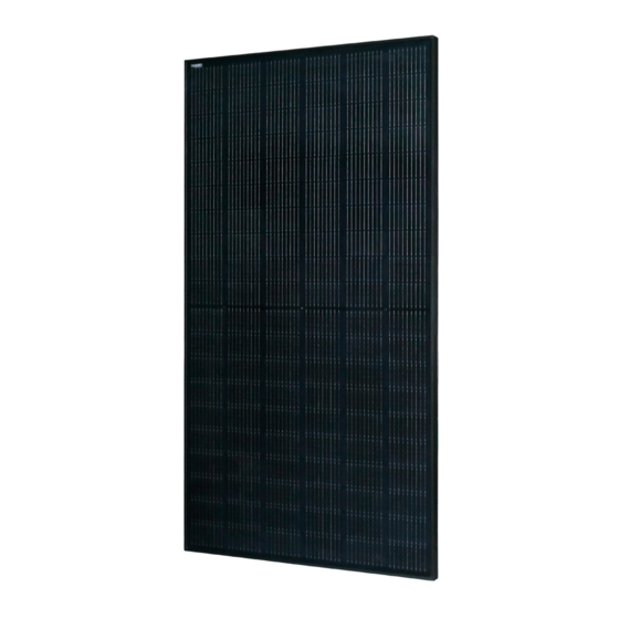
- Page 1 INSTALLER MANUAL Beam Series Crystalline Silicon PV Modules Installation Manual Version 1.4,Released in April 2023. This guide describes how to install the Energizer Solar Beam crystalline silicon PV modules. To prevent improper operation before use, please carefully read this manual.
-
Page 2: Table Of Contents
Table of contents Table of contents ..........................2 Important notes ..........................3 Laws and regulations ......................... 3 Safety measures ..........................3 Handling and unpacking ........................6 Mechanical installation ........................10 Electrical Installation ........................15 Maintenance ............................ 19 Modified version and date ........................20 8 Star Energy Pty Ltd | Level 35, 477 Collins Street, Melbourne VIC 3000 | https://www.energizersolar.com 8 Star Energy ESS Ltd | The Black Church, St Mary’s Place, Dublin DO7 P4AX, Ireland... -
Page 3: Important Notes
2.3 Safety Energizer Solar reserves the right to update this Please read all the instructions in this manual manual without prior notice. - Page 4 All safety rules should be read compounds (such DOP, plasticizers), understood before aromatics, phenols, ketones, halogenated installing, wiring, handling, substances, mineral oil, alkanes (Such as and/or maintaining gasoline, cleaning lubricants, electronic photovoltaic modules. When resurrection agents), alcohol, certain drugs photovoltaic module exposed (white flower oil, active oil, bone-setting water,...
- Page 5 When the photovoltaic modules are electrically • 4.2 Operational safety measures connected choose a dry and low sunlight period, • During transportation storage, avoid preferrably morning or evening; or use opaque packaging damage due to falls or mis-treatment; materials to completely cover the surface of the ensure that the packaging boxes are ventilated, photovoltaic modules...
-
Page 6: Handling And Unpacking
frame, except when it is connected to the typhoons, photovoltaic modules that have not been ground. Scratches may cause corrosion of the installed may also be scraped away. frame, affecting frame's load-bearing capacity and long-term reliability. 5.1 Transport If the photovoltaic module glass or other •... - Page 7 the load. Adjust the position of the sling to 2. Select a suitable tonnage forklift according to ensure the center of gravity is stable and keep the module weight, the fork distance should be moving at a stable speed. Place the package adjusted to the maximum position without any lightly on a flat ground and right the package.
- Page 8 turning, so as to avoid sudden stop and rapid start. 3. When using the hydraulic vehicle to transport the modules, the distance between the upper surfaceof the fork and the ground should be less than or equal to 75mm. Backrest: height≥1.7m, width ≥1.5m Cushion materials in front of the backrest Forklift operation Due to the limitation of the height of...
- Page 9 items to hold one side of the long side frame, and 10. Tear off the anti-fallen tape on the first module then cut the other side. Two people can then move in the front, and then take out the modules in and take out the photovoltaic modules one by one order around the frame;...
-
Page 10: Mechanical Installation
(such as salt, salt spray, module. salt water, active chemical vapor, acid rain, strong Energizer Solar PV modules adopt high and low steam, or any other substances that will corrode current bins, and the handlers need to place them... - Page 11 module, and avoids long-term large amounts of and the roof is 10cm, and air circulation is accumulated water leaving marks on the glass required to prevent damage to the wiring of the surface, thereby affecting the appearance and photovoltaic module. performance of the module.
- Page 12 Figure 9: 400mm spacing bolt installation Figure 5: Outer four-hole bolt installation for 72 cell for 72cell In order to achieve maximum safety precautions against wind and snow loads, it is recommended that all available mounting holes should be used. Figure 6: Internal four-hole bolt installation for 72cell Bolts are inserted as described in the process below.
- Page 13 x M6 stainless steel bolts are required (Figure Secure each bolt frame with ③ stainless-steel washers, one for each side of the mounting structure; and screw on either a stainless-steel spring washer or a toothed lock washer. Finally, secure with a stainless steel nut. Figure 13: Four clamp mounting on short The reference value of tightening torques should ④...
- Page 14 The clamp must overlap the module frame by at 17~23Nm when the property class of bolts and least 8mm but no more than 11mm (The clamp screws is Class 8.8. section can be changed under the premise of ensuring reliable installation components).
-
Page 15: Electrical Installation
Table 2 Installation range and corresponding values Installation method Dimensions Module type Figure Fig 13 L*W*H (mm) Fig 6 Fig 11 Fig 12 Fig 7,8,9 2, 3, 4, 5 +5400/-2400Pa +1800/-1800Pa +1800/-1800Pa 1708*1133*30 +5400Pa Installation Installation Installation 1708*1133*35 -2400Pa scope scope scope ENSP54M2... - Page 16 ratings and capacities. Depending on your local The string voltage must not be higher than the regulations, an additional 1.25 multiplier forthe maximum system voltage, as well as the maximum Isc(giving a total multiplier of 1.56) may be input voltage of the inverter and other electrical applicable when sizing conductors and fuses.
- Page 17 the corresponding open-circuit voltage of the module 7.2 Installation conditions (°C) under STC condition, and is the lowest In order to ensure the normal operation of the on-site temperature. 25 ℃ is the standard cell system, when connecting photovoltaic modules or temperature, and x% is the temperature coefficient connecting loads (such as inverters, batteries, etc.), corresponding to the open-circuit voltage from the...
- Page 18 • When the cable is fixed on the bracket, it is 7.3 Grounding necessary to avoid mechanical damage to the Energizer Solar modules use an anodic oxidized cable or photovoltaic module, and do not press aluminum frame to resist corrosion. So the frame of the cable with force.
-
Page 19: Maintenance
suitable for electrical bonding and grounding PV modules to PV mounting systems. Other grounding methods may be allowable • when tested with the racking system per UL 2703 requirements. Please don’t drill any additional grounding • hole on the frame of the modules. •... -
Page 20: Modified Version And Date
Support Number: +61 1300 757 827 © 2023 Energizer. Energizer and certain graphic designs are trademarks of Energizer Brands, LLC and related subsidiaries and are used under license by 8 Star Energy Pty Ltd. All other brand names are trademarks of their respective owners. Neither 8 Star Energy Pty Ltd nor Energizer Brands is affiliated with the respective owners of their trademarks.
Need help?
Do you have a question about the Beam Series and is the answer not in the manual?
Questions and answers