Sign In
Upload
Download
Table of Contents
Contents
Add to my manuals
Delete from my manuals
Share
URL of this page:
HTML Link:
Bookmark this page
Add
Manual will be automatically added to "My Manuals"
Print this page
×
Bookmark added
×
Added to my manuals
Manuals
Brands
Energizer Manuals
Inverter
ENK1100
User manual
Energizer ENK1100 User Manual
Power inverter
Hide thumbs
1
2
3
4
5
6
7
8
9
10
11
12
13
14
15
16
17
18
19
20
Table Of Contents
21
page
of
21
Go
/
21
Contents
Table of Contents
Troubleshooting
Bookmarks
Table of Contents
Warnings, Cautions, and Notes
Appliance Cautions
Getting Started
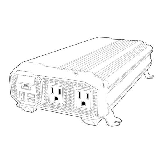
LCD Diagram
Sizing the Battery Bank
Cable Gauges
Mounting the Inverter
Connecting the Inverter
Operation
Television and Audio Suggestions
Troubleshooting
Return Material Authorization Policy
Return Procedure
Advertisement
Quick Links
1
Troubleshooting
Download this manual
ENK1100/ENK1500/ENK2000
POWER INVERTER
USER'S MANUAL
E11347
9
Conforms to / Conforme à UL std. 458,
Certified to / Homologué à
CSA std. C22.2 No. 107.1
Table of
Contents
Previous
Page
Next
Page
1
2
3
4
5
Advertisement
Table of Contents
Need help?
Do you have a question about the ENK1100 and is the answer not in the manual?
Ask a question
Questions and answers
Related Manuals for Energizer ENK1100
Inverter Energizer EN1100 User Manual
110 volt (21 pages)
Inverter Energizer ENA548 Owner's Manual
(20 pages)
Inverter Energizer EN150 Owner's Manual
(24 pages)
Inverter Energizer Beam Series Installer Manual
Crystalline silicon pv modules (20 pages)
Inverter Energizer ENK1500 User Manual
Power inverter (21 pages)
Inverter Energizer ENK2000 User Manual
Power inverter (21 pages)
Inverter Energizer ENK3000 User Manual
(21 pages)
Inverter Energizer ENK4000 User Manual
(21 pages)
Inverter Energizer EZG1300 User Manual
(39 pages)
Inverter Energizer eZV3200 User Manual
(48 pages)
Inverter Energizer EZG Series Manual
(122 pages)
Inverter Energizer eZV 4500W i-Series User Manual
(124 pages)
Inverter Energizer EZG2001I-UK User Manual
(78 pages)
Inverter Energizer PURE SINE EP150 Instruction Manual
150w wave inverter (12 pages)
Inverter Energizer FORCE Series Installer Manual
Solar grid-tied (27 pages)
Inverter Energizer FORCE S Series Installer Manual
(29 pages)
This manual is also suitable for:
Enk1500
Enk2000
Table of Contents
Print
Rename the bookmark
Delete bookmark?
Delete from my manuals?
Login
Sign In
OR
Sign in with Facebook
Sign in with Google
Upload manual
Upload from disk
Upload from URL


Need help?
Do you have a question about the ENK1100 and is the answer not in the manual?
Questions and answers