Advertisement
Quick Links
Advertisement
Chapters
Troubleshooting

Related Manuals for MINOLTA-QMS 4060


Summary of Contents for MINOLTA-QMS 4060
- Page 1 4060 Service and Parts Manual 1750040-001A...
-
Page 3: Table Of Contents
General Information SERVICE MANUAL CHAPTER 1 GENERAL INFORMATION Chapter 1 contents include Section Introduction...................... Printer Specifications ..................1-2.1 Printer General Specifications ............1-2.2 Printer Print Speed Specifications ..........1-2.3 Printer Physical Specifications ............. 1-2.4 Printer Electrical Specifications............ 1-2.5 Environmental Specifications For All Equipment ......Summary of Printer Optional Features and Feature Specifications.... - Page 4 General Information SERVICE MANUAL NOTE This page intentionally left blank.
-
Page 5: Introduction
1-1. Introduction This chapter provides specifications, safety compliance, options, available supplies, printing paper and design, system configuration, related manuals, and servicing approach for the 4060 cut sheet printer and supporting optional Large-Capacity Hopper (LCH) and Large-Capacity Stacker (LCS) paper handlers. -
Page 6: Printer Specifications
) face down tray • 2,000 sheets optional Large-Capacity Stacker (LCS) 1-2.2. Printer Print Speed Specifications Table 1-2 lists the specifications for the 4060 printer print speeds. Table 1-2. 4060 Printer Print Speed Specifications Paper Size (direction) Simplex *2 Duplex *2... -
Page 7: Printer Physical Specifications
*2: Unit of measure: Images Per Minute (IPM). All the speeds have ±5% tolerance. 1-2.3. Printer Physical Specifications Table 1-3 lists the printer physical specifications. Figure 1-2 illustrates the physical specifications and Figure 1-3 illustrates the required printer service area dimensions. Table 1-3. 4060 Printer Physical Specifications Item Specification Dimensions Width Depth Height 585 mm (23.0 in) - Page 8 General Information SERVICE MANUAL 40.5 in. (1030 mm) 23.0 in. 1.38 in 25.2 in. (585 mm) (35 mm) (640 mm) Figure 1-2. 4060 Printer Physical Dimensions...
-
Page 9: Environmental Specifications For All Equipment
55 dBA or less (printer only) Dust 0.15 mg./m (stearic acid) Ozone emission 0.1 PPM or less 1-3. Summary of Printer Optional Features and Feature Specifications Table 1-6 lists the options available with the 4060 printer along with their associated specifications. - Page 10 General Information SERVICE MANUAL Table 1-6. 4060 Printer Available Options and Specifications Summary Item Specification Model Number Large-Capacity Hopper 4060 (Letter) 3,000 sheets (75 g/m (LCH) 4060 (A4) Large-Capacity Stacker 4060 (120 VAC) 2,000 sheets (75 g/m (LCS) 4060 (240 VAC)
-
Page 11: Large-Capacity Hopper (Lch)
Models 4060 and 4060 are the user-installable optional Large-Capacity Hoppers (LCH) units for the 4060 printer, connecting to the right side of the printer. The 4060 can feed Letter size paper only, and the 4060 can feed A4 size paper. Both LCHs can be installed up to 3000 sheets of paper (75g/m2). -
Page 12: Lch Physical Specifications
General Information SERVICE MANUAL Processing speed 40 ppm (4060: Letter landscape and 4060: A4 landscape) Paper Size 4060: Letter and 4060: A4 Type Plain paper, Label paper, Transparency, Bond paper, Pre-punched paper 64 to 90g/m Paper capacity 3,000 sheets (75g/ m 1-4.3. -
Page 13: Lch Electrical Specifications
Table 1-9 lists the LCH electrical specifications. Table 1-9. LCH Electrical Specifications Item Specification Input power 24VDC, supplied from 4060 printer Power consumption 30VA or less during operation 1-4.5. LCH Environmental Specifications Refer to Table 1-5 for LCH environmental specifications. -
Page 14: Large-Capacity Stacker (Lcs)
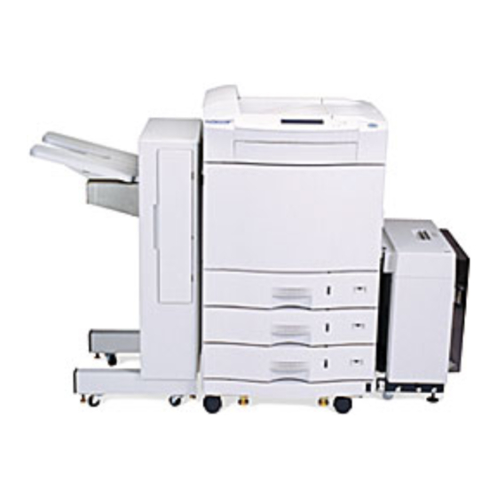
Figure 1-6 shows the user-installable optional Large-Capacity Stacker (LCS) paper handler that connects to the left side of the printer. Model 4060 is for 120V, and model 4060 is for 240V. The LCS can stack up to 2000 sheets of paper (75g/m2). -
Page 15: Lcs Physical Specifications
850 mm (33.5 in) 850 mm (33.5 in) 1-5.4. LCS Electrical Specifications Table 1-12 lists the LCS electrical specifications. Table 1-12. LCS Electrical Specifications Specification Item 4060 4060 Input Power Voltage 100 to 120 VAC 200 to 240 VAC ±10% ±10%... -
Page 16: Printer Custom Paper Tray
1-6. Printer Custom Paper Tray Model 4060 printer custom paper tray is user-installable, optional custom paper tray for the 4060 printer that is compatible and switchable with the standard printer paper tray. The custom paper tray can hold up to 500 sheets (75g/m2) of free sized paper as listed in Table 1-13 specifications. - Page 17 General Information SERVICE MANUAL (2) All the listed values are theoretical. The damage due to improper handling, maintenance, papers, environments, and other uncontrollable occasions are not considered in these values. (3) All the values for replacement cycle/life shown above depends on printing usage’s and conditions: Drum Counts: The drum counter will increment every 150 seconds (equals 100 •...
-
Page 18: Best Printing Area Specifications
Margin Best area Figure 1-7. Best Printing Area If data is printed outside the best printing area, you may obtain poor print quality Figure 1-8 shows the print area of the 4060 printer. Feed direction Paper | D-E | 1.5 mm | F-G | 1.5 mm... - Page 19 General Information SERVICE MANUAL Table 1-16. Print Area Specifications A (mm) B (mm) A (mm) B (mm) 139.6 201.6 LEDGER 271.0 423.4 288.6 201.6 EXECUTIVE 175.75 258.3 288.6 411.6 B5(JIS) 248.6 355.6 LETTER 271.0 207.5 B4 (JIS 173.6 248.6 LEGAL 207.5 347.2 Figure 1-9 shows the printing position precision.
- Page 20 General Information SERVICE MANUAL Ideal print area Print area – MAGNIFICATION Paper | H-I | 2.5 mm | J-K | 1.5 mm Feed direction Print section – SKEW Paper | A-B | 2mm/432mm Feed direction – OFFSET Paper | D-E | 1.5 mm | F-G | 1.5 mm...
-
Page 21: System Configuration Component Locations And Descriptions
General Information SERVICE MANUAL 1-9. System Configuration Component Locations and Descriptions 1-9.1. Front and Right Side of the Printer Ejection unit Standby switch Display contrast Paper stacker shelf Control panel ... . Front cover . -
Page 22: Behind The Front Door
General Information SERVICE MANUAL The LCH cover should be exchanged to the paper input guide when LCH is installed. • The Lower right cover covers the paper path from the paper trays. • The Paper size indicators show what size of paper is in each tray. •... - Page 23 General Information SERVICE MANUAL When you open the front door of the printer, you see the printer internal components shown in Figure 1-11: The Fuser unit applies heat and pressure to the paper using upper and lower rollers which • fuse the toner to the paper.
-
Page 24: Behind The Upper Right Cover
General Information SERVICE MANUAL 1-9.3. Behind the Upper Right Cover ....Toner collector bottle Developer collector bottle Toner hopper Developer unit Upper right cover Figure 1-12. -
Page 25: 1-9.4 Behind The Lower Right Cover
General Information SERVICE MANUAL 1-9.4. Behind the Lower Right Cover Upper paper feed unit Middle paper feed unit Lower paper feed unit Figure 1-13. Printer Lower-right Side View By opening the lower right cover, you gain access to the paper feed units as shown in Figure 1-13: The Upper, Middle, and Lower paper feed units feed paper picked from the three paper •... -
Page 26: Rear And Left Side Of The Printer
General Information SERVICE MANUAL 1-9.5. Rear and Left Side of the Printer Main controller (Under top cover) Optical unit (Under main controller) Ejection unit Upper left cover LCS cover Ozone filter LCS attachment points (under covers) LCH connector AC input power connector LCS connector Lower connector... - Page 27 General Information SERVICE MANUAL The LCS cover should be exchanged to the paper exit guide when LCS is installed. • The LCS attachment covers conceal LCS securing hardware. • The LCS connector provides an LCS cable interface (if installed). • The Lower connector is for future upgrades.
-
Page 28: 1-9.6 Rear-Inside Of The Printer
General Information SERVICE MANUAL 1-9.6. Rear-Inside of the Printer Drive unit E High voltage Drive unit D power supply Drive unit M Low voltage power supply (Behind Mechanism Controller Board) Mechanism Controller Board Figure 1-15. Printer Rear Inside View The rear of the printer has the features shown in Figure 1-15: The Drive unit D controls toner feed drive screw for toner flow control. -
Page 29: 1-9.7 Large-Capacity Hopper (Lch) Accessory
General Information SERVICE MANUAL The Drive unit M controls the printer print unit. • The High voltage power supply develops and regulates high voltages to the drum unit • components (precharger, photoconductor drum, and cleaning unit), the transfer assembly components (transfer charger and AC charger) and the developer unit. The Low voltage power supply develops and regulates low voltages used by the motors •... -
Page 30: 1-9.8 Large-Capacity Stacker (Lcs) Accessory
General Information SERVICE MANUAL The see-through LCH door allows visual inspection of the paper supply. • The Door handle provides easy access to the paper supply. • The elevator-type movable Paper shelf supports the paper supply. • 1-9.8. Large-Capacity Stacker (LCS) Main Power Switch Input power cord connector LCS Interface... -
Page 31: 1-10. Printer Component Block Diagram
General Information SERVICE MANUAL 1-10. Printer Component Block Diagram ACIN (006) (005) AC1J DCNJ10 ACIN CN10 OPTICAL UNIT LV POWER SUPPLY SPJ4 CNFAN2 CNFAN1 CNFAN2J CNFAN1J DCNJ6 DCNJ7 DCNJ5 DCNJ3 (006) +12V (005) (005) FAN5P FAN4P (006) (024) (024) (006) (006) OPPJ HDDJ... - Page 32 General Information SERVICE MANUAL (023) (023) (022) (024) (024) (022) OPTICAL UNIT OPERATOR PANEL MAIN CONTROLLER (015, (022) INF0 016) (022) (014, (014) 015, HV1J 016) HV POWER SUPPLY (014, (008) (008) (015, 015, TNSP TEMPP (014) (008) 016) 016) TNSJ TEMPJ CNJ16...
- Page 33 General Information SERVICE MANUAL FUSER UNIT FUSER TEMPERATURE INTERLOCK SWITCH SWITCH LAMP STACKER FULL (005) TINTSW ACN4J THERMISTOR PS6P PS7P STFL LV POWER SUPPLY CNTP CNTJ SWITCH STACKER PURGE DUPLEX BACK SELECT MOTOR MOTOR SOLENOID SOLENOID TONER REGIST DISCHARGING MAIN ROLLER SCREW DRUM...
- Page 34 General Information SERVICE MANUAL DISCHARGE CLED FAN1J FAN2J FAN6J FAN7J CLEDJ FAN1P FAN2P FAN6P FAN7P CLEDP PS2J PS3J PS4J +12V (007) (007) (007) (007) (020) (020) (020) (020) (002) (007) (020) CNJ22 CNJ23 CN22 CN23 MECHANISM CONTROLLER CN12 CN13 CNJ7 CNJ12 (021) (021)
-
Page 35: 1-11. Safety And Regulatory Information
General Information SERVICE MANUAL 1-11. Safety and Regulatory Information The safety and regulatory information for the 4060 printer is located in the 4060 User Manual. 1-12. Servicing Approach The printer is serviced by: (1) Understanding the layout and specifications of the printer and the associated options as described in this chapter. - Page 36 General Information SERVICE MANUAL 1-13. Interior Label This product is a Class I laser product. The warning labels shown are located outside on the optical unit. Caution Use of controls or adjustment of performance for procedures not specified herein way result in hazardous radiation exposure.
- Page 37 Theory of Operation SERVICE MANUAL CHAPTER 2 THEORY OF OPERATION Chapter 2 contents include: Section Introduction...................... Overview of Printing Process ................2-2.1 Mechanical Operation ..............2-2.2 Video Data Control ............... 2-2.3 Developer Replacement ..............2-11 Paper Feed Operation..................2-16 2-3.1 Operational Timing Charts ............
-
Page 38: Introduction
Theory of Operation SERVICE MANUAL 2-1. Introduction This chapter describes the 4060 printer printing process with overviews of the mechanical components, functions, and timing sequences. 2-2. Overview of Printing Process This section describes the printing process through an overview of the mechanical and functional operations. - Page 39 Theory of Operation SERVICE MANUAL Main Controller OPTICAL UNIT Photoconductor Power Supply Unit Photo Diode Drum Optical Unit Laser Diode Controller PCB Reflector 2 +24V DC On/Off Control Reflector 1 Circuit Laser Driver Video Interface Eject cover Circuit interlock switch Laser Driver Mechanism...
- Page 40 Theory of Operation SERVICE MANUAL Laser Source unit (including laser diodes, collimator lens, etc.) Rotating mirror Laser Diode A [5mW, 1=780nm] Laser Diode B Scanning lens 1 [5mW, 1=780nm] LaserBeam Beam Detector (BD) Refractor 1 Scanning lens 2 Refractor 2 Cover glass Scanning line Scanning directions...
-
Page 41: Video Data Control
Theory of Operation SERVICE MANUAL The developer unit stirs two-component developer (toner and carriers) to generate frictional electricity. The charged toner sticks to the laser-applied area (-100 V) on the photoconductor drum. Transfer assembly The transfer assembly transfers a toner image from the photoconductor drum to a paper. This transfer is caused by the corona charge from the back side of the paper by the positive charge. - Page 42 Theory of Operation SERVICE MANUAL VS is the video synchronization signal in the paper feeding (secondary scanning) direction. r *VR e *VS w *BD q *VIDEO Tvs(*1) Tvp: Printing-assured area Tv: Printing area Figure 2-4. Printing Control in Paper Transport Direction (VIDEO Control) Note: The Tvs time is equivalent to the distance of 5 millimeters.
- Page 43 Theory of Operation SERVICE MANUAL min. 1 µs Tbd: BC period *VIDEO Twp: Printing-assured area (82) Tw: Printing area (*1) Thd (*3) *VIDEO Tvd: 1 dot Figure 2-5. Printing Control In Beam Main Scan Direction (VIDEO Control) Notes: The Tw time is equivalent to the printing paper width. The printing-not-assured area in the paper width direction begins at a position 5 millimeters from the left edge of the paper.
- Page 44 Theory of Operation SERVICE MANUAL Table 2-2. VIDEO Signal Control Parameters (600 dpi, Depending On Paper Size) Printing in 600 dpi <TYPE A> Paper size W × V (mm) Tv (ms) Tvp (ms) Thd (µs) Tw (µs) Twp (µs) A3 portrait 2333.37 2277.86 2.801 to 3.667...
- Page 45 Theory of Operation SERVICE MANUAL 1 scanning cycle Beam detection signal from the Optical Unit Start signal to the main controller via video interface Video data from the main controller via video interface V.D.2 V.D.3 V.D.4 V.D.5 V.D.6 V.D.7 VIDEO Interface Circuit ED ON ED ON...
-
Page 46: Developer Replacement
Theory of Operation SERVICE MANUAL 2-2.3. Developer Replacement The operator must replace the developer by using the developer replacement command DVEXC. The developer replacement request (MESG) and developer end life (OPC) are reset by completing the developer replacement. Replace the developer in the following procedure: Developer replacement start direction −>... - Page 47 Theory of Operation SERVICE MANUAL [Restrictions] This command is valid when the PRSQ1 value is one of the following: • - $00 (out of operation) - $30 - $31 (initialization) If PRSQ1 is a value of $99 to $9F, the command is invalid, but is not rejected. •...
- Page 48 Theory of Operation SERVICE MANUAL [Restrictions] The developer pouring end command is not valid when PRSQl is other than $9E. • If PRSQl is a value other than those above, the command is rejected. • (4) Developer replacement procedure end: PARAl = $06 [Function] The developer replacement procedure end command directs the printer to end the •...
- Page 49 Theory of Operation SERVICE MANUAL developer replacement operation suppression error was detected or the printer power was turned off during developer ejection operation. The only developer replacement command that can be accepted and executed in this • status is the developer ejection start command. When the printer power is turned off then on in this state, the printer is set to the •...
-
Page 50: Paper Feed Operation
Theory of Operation SERVICE MANUAL status is the developer replacement end command. When the printer power is turned off then on in this status, the printer resets the • developer replacement request (MESG) and developer life end state (OPC). The printer also places the specified developer life value into the developer life management counter. - Page 51 Theory of Operation SERVICE MANUAL Figure 2-10 "Double-sided Printing Sequence Timing Chart," Page 2-19 • Table 2-3 "Printing Sequence Specifications," Page 2-20 • Figure 2-11 "Prepick Sequence Timing Diagram and Charts," Page 2-21 • Table 2-4 "Jam Codes, Names, Conditions and Messages," Page 2-22 •...
- Page 52 Theory of Operation SERVICE MANUAL Refer to Figure 2-8 "Paper Feed Operation Timing Chart": When the power is turned on and when the cover is opened, then shut, or when the error reset command is received: Power ON Spindle motor Temperature = 185°C Fuser Process operation...
- Page 53 Theory of Operation SERVICE MANUAL Refer to Figure 2-9 "Printing Sequence Timing Chart": (Controller) PSTRT PEND PEND DREQ DREQ (Printer) PSTRT Process Prepared Exposed Not Exposed Exposed operation PRSQ1 Pick operation Max. 35 sec 0 to 10 sec (= 0: Maximum processing speed) If t2 exceeds 10 seconds, the VS alarm occurs.
- Page 54 Theory of Operation SERVICE MANUAL Refer to Figure 2-10 "Double-sided Printing Sequence Timing Chart": An example of duplex printing sequence is shown below. Two pages can be contained in the double-sided printing path. Only one page can be contained for the A3 and Ledger portrait size paper.
- Page 55 Theory of Operation SERVICE MANUAL Table 2-3. Printing Sequence Specifications Paper size Table 1þþms Table 2þþms A5 (V) Letter (H) A4 (H) Legal (V) NOTE For A3 (V) and legal (V) paper, the printing sequence supports single-sheet sending. 2-19...
- Page 56 Theory of Operation SERVICE MANUAL Refer to Table 2-11 "Prepick Sequence Timing Diagram and Charts": One page One page DREQ Two pages PREPK VR VS PEND VR VS command Two pages pages (Controller) One page PREPK PSTRT VR VS command (Printer) BSTR3, PKPQ...
- Page 57 Theory of Operation SERVICE MANUAL Refer to Table 2-4 "Jam Codes, Names, Conditions and Messages" and Figure 2-12 "Position of Jam Detection Sensors": Table 2-4. Jam Codes, Names, Conditions and Messages Jam Code Jam Name Definition Message Jam 0-1 Paper did not reach sensor PS1-1 from the upper tray before specified Paper tray 1 pick error time passed after the pick roller started.
- Page 58 Theory of Operation SERVICE MANUAL Table 2-4. Jam Codes, Names, Conditions and Messages (Cont) Jam Code Jam Name Definition Message STK Jam 1 When the printer is reset, there is paper blocking one of the LCS paper LCS jam 1 sensors.
- Page 59 Theory of Operation SERVICE MANUAL Ejection tray full (ESF) Ejection tray (ES7) Photoconductor drum (ES6) Fuser Register roller PS1-1 (FS11) Paper feed unit (DS5) PS1-2 (FS12) Upper tray PS1-3 (FS13) Middle tray Lower tray Figure 2-12. Position of Jam Detection Sensors 2-23...
-
Page 60: Printer Power
Theory of Operation SERVICE MANUAL 2-4. Printer Power Chapter 1 provides the overall printer interconnection block diagram and appendix A provides the detailed printer interconnection wiring diagram. This section provides the functional block diagrams of the low and high power supplies and also the timing chart of the power-on sequence. 2-4.1. - Page 61 Theory of Operation SERVICE MANUAL AC INPUT AC INPUT JUDGEMENT CIRCUIT JUDGEMENT CIRCUIT (VOLTAGE) (INPUT OR NOT) PC4, Q9, D20, ETC PC2, Q10, ETC TRIAC DRIVER PFC CIRCUIT FOR THE HEATER PC4, PC1, Q102, PC3, L7, Q1, Q2 Q103, ETC RC2, Z1, ETC AUXILIARY POWER CIRCUIT...
-
Page 62: 2-4.2 High Voltage Power Supply Block Diagram
Theory of Operation SERVICE MANUAL 2-4.2. High Voltage Power Supply Block Diagram Figure 2-14 through Figure 2-18 illustrate the high voltage power supply major functions. REGULATOR +DC24V (+DC5V) +DC6V INVERTER ANALOG (LS14) CONTROLLER D/A CONVERTER ANALOG CONTROLLER ANALOG ACH (AC) CONTROLLER ANALOG INVERTER... - Page 63 Theory of Operation SERVICE MANUAL TRANSFORMER (T1) +DC24V RECTIFIER CIRCUIT +DC5V OSCILLATION CONTROLLER -HVON HVALM ALARM DETECTOR Figure 2-15. HVPS -HV Block Diagram Block Diagram TRANSFORMER (T2) +DC24V RECTIFIER CIRCUIT +DC5V OSCILLATION CONTROLLER +HVON ANALOG D/A CONVERTER CONTROLLER HVALM ALARM DETECTOR Figure 2-16.
- Page 64 Theory of Operation SERVICE MANUAL TRANSFORMER (T3) +DC24V RECTIFIER CIRCUIT +DC5V OSCILLATION CONTROLLER VBON ANALOG D/A CONVERTER CONTROLLER HVALM ALARM DETECTOR Figure 2-17. HVPS VB Block Diagram +DC24V TRANSFORMER +DC5V (T4) ACH (Vpp) RESONANT ACHON CONVERTER CONTROL OSCILLATOR ANALOG CIRCUIT CIRCUIT D/A CONVERTER CONTROLLER...
-
Page 65: Power-On Sequence Timing Chart
Theory of Operation SERVICE MANUAL 2-4.3. Power-on Sequence Timing Chart Figure 2-19 illustrates the printer power-on timing sequence. " " means the active-low signal. Main Switch *Standby Switch +5V, +12V MAIN CONTROLLER STARTS (Power start 2; always low unless any interlock activated) *POWST2 *PWRRDY (Power Ready) - Page 66 Theory of Operation SERVICE MANUAL 2-30...
- Page 67 Printer Maintenance Program SERVICE MANUAL CHAPTER 3 PRINTER MAINTENANCE PROGRAM This chapter must be developed for the 4060 printer maintenance program, if installed, driven by the main controller and the software installed. 31-1...
- Page 68 Printer Maintenance Program SERVICE MANUAL 31-2...
- Page 69 General Troubleshooting SERVICE MANUAL CHAPTER 4 GENERAL TROUBLESHOOTING Chapter 4 sections include: Section Introduction...................... Troubleshooting Overview ................Error Message and Problem Summaries............Standard Tools and Test Equipment ..............Hints and Tips ....................
- Page 70 4-2. Troubleshooting Overview Troubleshooting the 4060 printer and the optional Large-Capacity Hopper (LCH) begins by recognizing a fault condition whether reported by the machines or by observation. This chapter provides one location for summaries of information found elsewhere in this manual and also provides reference diagrams and procedures that may be referenced by many troubleshooting flow charts.
- Page 71 General Troubleshooting SERVICE MANUAL Table 4-1. Sensor Codes and Messages Displayed Code Code Meaning or Problem Description SVC08 Upper Pick Motor Alarm SVC09 Middle Pick Motor Alarm SVC0A Lower Pick Motor Alarm SVC0B Reversing Motor Alarm SVC0D Feed Motor Alarm SVC0E Stacker Select Solenoid Alarm SVC0F...
- Page 72 General Troubleshooting SERVICE MANUAL Table 4-1. Sensor Codes and Messages (Cont) Displayed Code Code Meaning or Problem Description SVCA0 Fan Alarm 1 SVCA1 Fan Alarm 2 SVCA5 Fan Alarm 6 SVCA6 Fan Alarm 7 SVCB0 Watchdog Timer Alarm - Master) SVCB1 Watchdog Timer Alarm - Slave) SVCB3...
- Page 73 General Troubleshooting SERVICE MANUAL Table 4-2. Jam Codes and Messages (Cont) Jam Code Jam Name Definition Message Jam 1-8 When the printer is reset, there is paper at PS2, or Feed path 4 jam Paper did not reach PS3 before specified time passed after the paper reached PS2. Jam 3-1 When the printer is reset, there is paper at PS3.
- Page 74 General Troubleshooting SERVICE MANUAL - 12-inch for toner hopper hose maintenance Flat head screwdriver (long): • - 1/8-inch blade to adjust LVPS +5V output - 1/4-inch blade for general maintenance Small metric-scaled ruler to measure paper registration • Isopropyl alcohol for cleaning optics lens and other surfaces. •...
- Page 75 General Troubleshooting SERVICE MANUAL Fan 1 Fan 6 Fan 4 Notes: Fan 2 All 24V fans stop when any interlock switch is opened. All 12V fans continue running regardless if any interlock switch is opened. Fan 7 Fan assignments are: Voltage Purpose Cool optical unit...
- Page 76 General Troubleshooting SERVICE MANUAL (5) Movable-bracket positioning-pins and locating-holes - Figure 4-2 illustrates proper reinstallation of critical hardware. A bracket misaligned due to careless remounting can cause expensive damage. Positioning Pin Pin MUST be in slot Positioning Slot Screw Slot (2x) Set Screw (2x) Figure 4-2.
- Page 77 Troubleshooting SERVICE MANUAL CHAPTER 5 TROUBLESHOOTING Chapter 5 contents include: Section 5-1. Troubleshooting Approach ................5-15 5-1.1. General Troubleshooting Flow Chart .......... 5-17 5-2. Alarm Error Message Reported Problems ............5-19 5-2.1. SVC08 Upper Pick Motor Alarm ..........5-20 5-2.2. SVC09 Middle Pick Motor Alarm ..........
- Page 78 Troubleshooting SERVICE MANUAL 5-2.34. SVCB1 Watchdog Timer Alarm—Slave ........5-150 5-2.35. SVCB3 Mechanism Controller Communication Alarm ... 5-152 5-2.36. SVCB4 EEPROM Alarm ............5-154 5-2.37. SVCB5 Video Synchronous (VS) Alarm ........5-156 5-2.38. SVCB6 Pre-pick Alarm .............5-158 5-2.39. SVCB7 Video Request (VR) Alarm ......... 5-160 5-12...
- Page 79 Troubleshooting SERVICE MANUAL 5-3. Paper Jam Error Message Reported Problems ..........5-163 5-3.1. JAM01/02/03 Pick Error ............5-164 5-3.2. JAM11/12/13 Feed Jam 1 ............5-172 5-3.3. JAM18 Feed Jam 2 ..............5-178 5-3.4. JAM25 Fuser Unit Jam 1 ............5-182 5-3.5.
- Page 80 Troubleshooting SERVICE MANUAL 5-7.1. JAM51 LCH Pick Error .............5-342 5-7.2. JAM52 LCH Feed Jam 1 ............5-354 5-7.3. JAM53 LCH Feed Jam 2 ............5-364 5-7.4. SVCC4 LCH Elevator Descent Alarm ........5-368 5-7.5. SVCC5 LCH Elevator Ascent Alarm ......... 5-372 5-8. LCH Miscellaneous Problems .................
-
Page 81: Troubleshooting Approach
5-1. Troubleshooting Approach The general troubleshooting flow chart provides a basic approach to troubleshooting 4060 Printer problems. Always proceed sequentially, throughout the flow and never assume the printer is functioning correctly without fully investigating the flow. If the problem still occurs when you reach the end of the flow, please contact your specialist with detailed information about the problem and what you have done for it. -
Page 82: General Troubleshooting Flow Chart
SERVICE MANUAL 5-1.1. General Troubleshooting Flow Chart Explanation Use this flow chart to begin the 4060 Printer fault isolation and repair. 5-16... - Page 83 SERVICE MANUAL Troubleshooting Procedure GO TO section 5-2 Is alarm error Alarm Error Message message displayed? Reported Problems! Is paper jam GO TO section 5-3 error message Paper Jam Error displayed? Reported Problems! Is problem GO TO section 5-4 power related Power Related problem? Problems!
-
Page 84: Alarm Error Message Reported Problems
SERVICE MANUAL 5-2. Alarm Error Message Reported Problems 5-18... - Page 85 SERVICE MANUAL 5-19...
-
Page 86: Svc08 Upper Pick Motor Alarm
SERVICE MANUAL 5-2.1. SVC08 Upper Pick Motor Alarm Explanation An overcurrent of the upper paper supply tray pick (stepper) motor was detected by the mechanism controller. Note that if any roller or shaft is locked or clogged, an overcurrent condition has not occurred. Troubleshooting Procedure Disconnect upper pick motor connectors PMP1 and PMPJ1... - Page 87 SERVICE MANUAL Reference Diagrams [SVC08] Mechanism Controller CNJ2 PMP1 PMJ1 Pick motor1 PSJ1 (PS1) +24V PLSJ1 (paper level sensor) PMPJ1 (paper empty sensor) PMP/J1 Figure 5-3. Upper Pick Motor Alarm (SVC08) Interconnections Diagram 5-21...
-
Page 88: Svc09 Middle Pick Motor Alarm
SERVICE MANUAL 5-2.2. SVC09 Middle Pick Motor Alarm Explanation An overcurrent of the middle paper supply tray pick (stepper) motor was detected by the mechanism controller. Note that if any roller or shaft is locked or clogged, an overcurrent condition has not occurred. Troubleshooting Procedure Disconnect middle pick motor connectors PMP2 and PMPJ2... - Page 89 SERVICE MANUAL Reference Diagrams [SVC09] Mechanism Controller CNJ3 PMP2 PMJ2 Pick motor2 PSJ2 (PS1) +24V PLSJ2 (paper level sensor) PMPJ2 (paper empty sensor) PMP/J2 Figure 5-5. Middle Pick Motor Alarm (SVC09) Interconnections Diagram 5-23...
-
Page 90: Svc0A Lower Pick Motor Alarm
SERVICE MANUAL 5-2.3. SVC0A Lower Pick Motor Alarm Explanation An overcurrent of the lower paper supply tray pick (stepper) motor was detected by the mechanism controller. Note that if any roller or shaft is locked or clogged, an overcurrent condition has not occurred. Troubleshooting Procedure Disconnect lower pick motor connectors PMP3 and PMPJ3... - Page 91 SERVICE MANUAL Reference Diagrams [SVC0A] Mechanism Controller CNJ4 PMP3 PMJ3 Pick motor3 PSJ3 (PS1) +24V PLSJ3 (paper level sensor) PMPJ3 (paper empty sensor) PMP/J3 Figure 5-7. Lower Pick Motor Alarm (SVC0A) Interconnections Diagram 5-25...
-
Page 92: Svc0B Reversing Motor Alarm
SERVICE MANUAL 5-2.4. SVC0B Reversing Motor Alarm Explanation An overcurrent of the reversing motor (stepper motor) of the reversing unit was detected in the mechanism controller. Note that if any roller or shaft is locked or clogged, the overcurrent is not occurred. - Page 93 SERVICE MANUAL Reference Diagrams [SVC0B] Mechanism Controller CNJ18 SBMP SBMJ CN18 Reversing motor STCHP STCHJ (stacker select solenoid) STSLP STSLJ +24V (purge solenoid) PS6P (PS6) SBMP/J PS7P (PS7) STFL (stacker full sensor) Figure 5-9. Reversing Motor Alarm (SVC0B) Interconnections Diagram 5-27...
-
Page 94: Svc0D Feed Motor Alarm
SERVICE MANUAL 5-2.5. SVC0D Feed Motor Alarm Explanation An overcurrent of the feed motor (stepper motor) of the transport assembly was detected in the mechanism controller. Note that if any roller or shaft is locked or clogged, the overcurrent is not occurred. - Page 95 SERVICE MANUAL Reference Diagrams [SVC0D] Mechanism Controller CNJ6 Feed motor CLM1J CLM1P (lift motor1) CLM2J CLM2P +24V (lift motor2) CLM3J CLM3P (lift motor3) FMP/J Figure 5-11. Feed Motor Alarm (SVC0D) Interconnections Diagram 5-29...
-
Page 96: Svc0E Stacker Select Solenoid Alarm
SERVICE MANUAL 5-2.6. SVC0E Stacker Select Solenoid Alarm Explanation An overcurrent of the stacker select solenoid of the reversing unit was detected in the mechanism controller. Note that if the selector or the solenoid itself is locked or clogged, the overcurrent is not occurred. - Page 97 SERVICE MANUAL Reference Diagrams [SVC0E] Mechanism Controller CNJ18 STCHP STCHJ CN18 Stacker select solenoid SBMP SBMJ (reversing motor) STSLP STSLJ (purge solenoid) +24V PS6P (PS6) CN18 STCHP/J PS7P (PS7) STFL (stacker full sensor) Figure 5-13. Stacker Select Solenoid Alarm (SVC0E) Interconnections Diagram 5-31...
-
Page 98: Svc0F Duplex Motor Alarm
SERVICE MANUAL 5-2.7. SVC0F Duplex Motor Alarm Explanation An overcurrent of the duplex motor (stepper motor) of the duplex unit was detected in the mechanism controller. Note that if any roller or shaft is locked or clogged, the overcurrent is not occurred. - Page 99 SERVICE MANUAL Reference Diagrams [SVC0F] Mechanism Controller CN20 Duplex motor PS5P (PS5) +24V CN20 DMP/J Figure 5-15. Duplex Motor Alarm (SVC0F) Interconnections Diagram 5-33...
-
Page 100: Svc27 Fuser Time-Out Alarm
SERVICE MANUAL 5-2.8. SVC27 Fuser Time-out Alarm Explanation It was detected from the thermistor in the fuser by the mechanism controller that the fuser unit did not reach the specified temperature (185 degC) when 200 seconds had passed after the power-on or cover closing. - Page 101 SERVICE MANUAL Troubleshooting Procedure Remove the fuser and verify that the input voltage rating (120V or 200V) located on the side of the fuser matches the printer. Replace the fuser The input voltage with a fuser with the rating matches. correct input voltage rating.
- Page 102 SERVICE MANUAL Check for the rated AC voltage at the LVPS side of the TINTSW switch. rated voltage is present: Replace LVPS. •120V:between pins 1B and 2B Verify repairs. •200V:between pins 3B and 2B SVC27 Exit! error still occur? Check for the rated AC voltage at the fuser side of the TINTSW switch.
- Page 103 SERVICE MANUAL Figure 5-16. SVC27 Fuser Time-out Alarm Flow Chart (2 of 3) Verify all printer covers are closed. Replace mechanism controller PCB. Transfer the Approximately 5V NVRAM from the continuous present. failed PCB to the new PCB. Replace LVPS unit. Figure 5-16.
- Page 104 SERVICE MANUAL Reference Diagrams [SVC27] Mechanism Controller CNJ21 CNTJ CNTP CN21 Fuser (main motor) DUSET CNJ8 COM/NO (drum interlock switch) Power supply DCNJ1 RCLP (regist roller clutch) SCRSJ (toner discharging screw sensor) ACN4J TINTSW TINTSW CNTJ/P (120V) (COM) (200V) (power supply) CN21 (mechanism controller) *HTON...
- Page 105 SERVICE MANUAL 5-39...
-
Page 106: Svc28 Fuser High-Temperature Alarm
SERVICE MANUAL 5-2.9. SVC28 Fuser High-temperature Alarm Explanation The fuser temperature is checked from the thermistor in the fuser by the mechanism controller every 500 ms. A temperature of 225 degC or higher was detected twice consecutively. 5-40... - Page 107 SERVICE MANUAL Troubleshooting Procedure Check for the rated AC voltage at the LVPS side of the TINTSW switch. rated voltage is present Replace LVPS. •120V: between pins 1A and 2A •200V: between pins 3A and 2A SVC28 error still occur? Verify all covers are closed.
- Page 108 SERVICE MANUAL Repair or replace damaged part. Pinched wires or cables, Verify repairs. or damaged connectors. SVC28 error Exit! still occur? Remove fan 4 and fan7. Check the resistance measurements on connector CNTJ (fuser connector on drive unit M) between: •pin3 and FG(frame ground) •pin7 and FG Reinstall fan4 and fan7, turn...
- Page 109 SERVICE MANUAL Figure 5-18. SVC28 Fuser High-temperature Alarm Flow Chart (2 of 2) Reference Diagrams [SVC28] Mechanism Controller CNJ21 CNTJ CNTP CN21 Fuser (main motor) DUSET CNJ8 COM/NO (drum interlock switch) Power supply DCNJ1 RCLP (regist roller clutch) SCRSJ (toner discharging screw sensor) ACN4J TINTSW TINTSW...
-
Page 110: 5-2.10. Svc29 Fuser Low-Temperature Alarm
SERVICE MANUAL 5-2.10. SVC29 Fuser Low-temperature Alarm Explanation The fuser unit temperature is checked from the thermistor in the fuser by the mechanism controller every 500 ms. A temperature of 155 degC or lower was detected twice consecutively. 5-44... - Page 111 SERVICE MANUAL Troubleshooting Procedure Check if the fuser is mounted correctly. fuser mounted Remount the fuser. correctly? SVC29 error Exit! still occur? Check for pinched wires, cables, and damaged connectors between CN21 on the mechanism controller PCB and the CNTJ (fuser connector) on the drive unit M.
- Page 112 SERVICE MANUAL rated voltage Replace LVPS. is present: •120V: between pins 1B and 2B •200V: between pins 3B and 2B SVC29 error Exit! still occur? Check for the rated AC voltage at the fuser side of the TINTSW switch. rated voltage is present: •120V: between pins 1A and 2A •200V: between pins 3A...
- Page 113 SERVICE MANUAL Figure 5-20. SVC29 Fuser Low-temperature Alarm Flow Chart (2 of 3) Check the HTON signal. Approximately Replace LVPS unit. 5V continuous is present. Replace mechanism controller PCB. Transfer the NVRAM from the failed PCB to the new PCB. Figure 5-20.
- Page 114 SERVICE MANUAL Reference Diagrams [SVC29] Mechanism Controller CNJ21 CNTJ CNTP CN21 Fuser (main motor) DUSET CNJ8 COM/NO (drum interlock switch) Power supply DCNJ1 RCLP (regist roller clutch) SCRSJ (toner discharging screw sensor) ACN4J TINTSW TINTSW CNTJ/P (120V) (COM) (200V) (power supply) CN21 (mechanism controller) *HTON...
- Page 115 SERVICE MANUAL 5-49...
-
Page 116: 5-2.11. Svc50 Toner Motor Alarm
SERVICE MANUAL 5-2.11. SVC50 Toner Motor Alarm Explanation An overcurrent of the toner motor (DC motor) of the toner hopper was detected in the mechanism controller. Troubleshooting Procedure Open the upper right cover and the set the actuator of the cover interlock switch. - Page 117 SERVICE MANUAL Reference Diagrams [SVC50] Mechanism Controller Toner hopper CN1J TNMJ TNMP Toner motor TEMPP TEMPJ (Toner empty sensor) TNSP TNST (toner density sensor) TNMJ/P MGSHJ MGSPH (developer discharge shutter motor) SWE26 COM/NO (developer discharge shutter switch) SWE25 COM/NO (developer waste bottle switch) Figure 5-23.
-
Page 118: 5-2.12. Svc51 Toner Discharge Screw Alarm
SERVICE MANUAL 5-2.12. SVC51 Toner Discharge Screw Alarm Explanation It was detected from the toner discharging screw sensor by the mechanism controller that the toner discharge screw did not rotate unless the main motor rotated. Troubleshooting Procedure Check whether the metal shaft (not the gear) of the waste toner screw is rotating when the main motor is turned on. - Page 119 SERVICE MANUAL Reference Diagrams [SVC51] Mechanism Controller CNJ21 SCRSJ CN21 Toner discharging screw sensor CNTJ (fuser unit) (main motor) RCLP (regist roller clutch) CN21 SCRSJ DUSET COM/NO (drum interlock switch) Figure 5-25. Toner Discharge Screw Alarm (SVC51) Interconnections Diagram 5-53...
-
Page 120: 5-2.13. Svc52 Developer Discharge Alarm
SERVICE MANUAL 5-2.13. SVC52 Developer Discharge Alarm Explanation It was detected from the toner density sensor in the developing unit by the mechanism controller that the developer is in the developing unit unless the developer was discharged. 5-54... - Page 121 SERVICE MANUAL Troubleshooting Procedure Check developer collector bottle. •Developer collector Replace developer collector bottle over full. bottle and clean spilt developer •Developer mixture completely under developer unit. discharged into bottle. SVC52 error still occur? Open the upper right cover and remove the rear cover and waste developer bottle.
- Page 122 SERVICE MANUAL When b1 is open, the developer coupling Replace drive unit M. moves to the rear allowing Verify repairs. removal of the developer assembly. When b1 closed, the developer coupling snaps forward to drive the developer gear. SVC52 error still occur? Check the voltage at TNDNS on the mechanism controller PCB.
- Page 123 SERVICE MANUAL Turn on the printer. Verify all covers are closed. SVC52 error Replace the developer unit. still occur? Verify repairs. SVC52 error still occur? Replace the mechanism controller PCB. Transfer the NVRAM from the failed PCB to new PCB. Exit! Figure 5-26.
- Page 124 SERVICE MANUAL Reference Diagrams [SVC52] Mechanism Controller Developing unit CN1J TNSP TNSJ Toner density sensor TNMJ TNMP (toner motor) TNSP/J TEMPP TEMPJ (toner empty sensor) MGSHJ MGSPH (developer discharge shutter motor) SWE26 COM/NO (developer discharge shutter switch) SWE25 COM/NO (developer waste bottle switch) Figure 5-27.
- Page 125 SERVICE MANUAL 5-59...
-
Page 126: 5-2.14. Svc54 Developer Discharge Shutter Alarm
SERVICE MANUAL 5-2.14. SVC54 Developer Discharge Shutter Alarm Explanation It was detected from the developer discharge shutter switch by the mechanism controller that the developer discharge shutter does not open at the developer discharge sequence. 5-60... - Page 127 SERVICE MANUAL Troubleshooting Procedure Open the upper right cover and remove the rear cover and waste developer bottle. Check the developer discharge shutter located on the bottom of the developer assembly. Replace drive unit D. Remove the The shutter is developer unit.
- Page 128 SERVICE MANUAL Turn on the printer. Verify all covers are closed. SVC54 error Exit! still occur? Replace mechanism controller PCB. Transfer the NVRAM from the failed PCB to the new PCB. Figure 5-28. SVC54 Developer Discharge Shutter Alarm Flow Chart (2 of 2) 5-62...
- Page 129 SERVICE MANUAL Reference Diagrams [SVC54] Mechanism Controller CN1J MGSHJ MGSHP Developer discharge shutter motor SWE26 COM/NO Developer discharge shutter switch (switch) TNSP TNSJ (toner density sensor) TNMJ TNMP (toner motor) TEMPP TEMPJ MGSHJ/P (toner empty sensor) SWE25 COM/NO (developer waste bottle switch) Figure 5-29.
-
Page 130: 5-2.15. Svc56 Automatic Adjustment Alarm
SERVICE MANUAL 5-2.15. SVC56 Automatic Adjustment Alarm Explanation At the automatic toner density adjustment after developer replacement, it is detected by the mechanism controller that the toner density sensor output voltage (can be monitored at the test point TNDNS W5 on the mechanism controller PCB) is not 2.5 + 0.2V. 5-64... - Page 131 SERVICE MANUAL Troubleshooting Procedure Remove the developer assembly. Open and close the developer release handle (b1) while observing the developer coupling. When b1 is open, the developer coupling moves Replace drive unit M to the rear allowing removal of and verify repair. the developer assembly.
- Page 132 SERVICE MANUAL Check voltage at test print TNDNS W5 on the mechanism controller PCB during the main motor turn-on while printer initializing. Replace mechanism controller The voltage is PCB. 2.5±0.2V. Transfer the NVRAM from the failed PCB to the new PCB. Check for pinched wires, cables, and damaged connectors between CN1 on the mechanism...
- Page 133 SERVICE MANUAL Check for the rated AC voltage at the LVPS side of the TINTSW switch. rated voltage is present Replace LVPS. •120V: bet ween pins 1A and 2A •200V: between pins 3A and 2A SVC 2S error Verify all covers are closed. sbill occur? Replace mechanism controller Approximately...
- Page 134 SERVICE MANUAL Reference Diagrams [SVC56] Mechanism Controller Developing unit CN1J TNSP TNSJ Toner density sensor TNMJ TNMP (toner motor) +12V TNSP/J TEMPP TEMPJ TNDNS W5 (toner empty sensor) MGSHJ MGSPH (developer discharge shutter motor) SWE26 COM/NO (developer discharge shutter switch) SWE25 COM/NO (developer waste bottle switch) Figure 5-31.
- Page 135 SERVICE MANUAL 5-69...
-
Page 136: 5-2.16. Svc57 Toner High-Density Alarm
SERVICE MANUAL 5-2.16. SVC57 Toner High-density Alarm Explanation Abnormal toner density sensor output voltage (0.98V or lower, it can be monitored at the test point TNDNS W5 on the mechanism controller PCB) was detected four times consecutively by the mechanism controller. (The toner density sensor was checked every 500 ms by the mechanism controller.) 5-70... - Page 137 SERVICE MANUAL Troubleshooting Procedure Remove the developer assembly. Open and close the developer release handle (b1) while observing the developer coupling. When b1 is open, the developer coupling moves to the rear allowing removal of Replace drive unit M. the developer assembly. When b1 is closed, the developer coupling snaps forward to drive the developer...
- Page 138 SERVICE MANUAL SVC57 error still occur? Replace mechanism controller PCB. Transfer the NVRAM from the failed PCB to the new PCB. SVC57 error still occur? Check for pinched wires, cables, and damaged connectors between CN1 on the mechanism controller PCB and TNSP connector near developer unit.
- Page 139 SERVICE MANUAL Replace toner hopper. SVC57 error verify repair. still occur? SVC57 error still occur? Replace developer unit. SVC57 error still occur? Replace mechanism controller PCB. Exit! Figure 5-32. SVC57 Toner High-density Alarm Flow Chart (3 of 3) 5-73...
- Page 140 SERVICE MANUAL Reference Diagram [SVC57] Mechanism Controller Developing unit CN1J TNSP TNSJ Toner density sensor CN10J TNMJ TNMP CN10 (toner motor) TEMPP TEMRJ (toner empty sensor) MGSHJ MGSPH (developer discharge shutter motor) SWE26 COM/NO (developer discharge shutter switch) Power supply DCNJ10 SWE25 COM/NO (developer waste bottle switch)
- Page 141 SERVICE MANUAL 5-75...
-
Page 142: 5-2.17. Svc58 Toner Low-Density Alarm
SERVICE MANUAL 5-2.17. SVC58 Toner Low-density Alarm Explanation Abnormal toner density sensor output voltage (4.04V or higher, it can be monitored at the test point TNDNS W5 on the mechanism controller PCB) was detected four times consecutively by the mechanism controller. (The toner density sensor was checked every 500 ms by the mechanism controller.) Note that this error may occurs when the printing is continued without supplying toner while clearing the “toner empty”... - Page 143 SERVICE MANUAL Troubleshooting Procedure Remove the developer assembly. Open and close the developer release handle (b1) while observing the developer coupling. When b1 is open, the developer coupling moves to the rear allowing removal of Replace drive unit M. the developer assembly. When b1 is closed, the developer coupling snaps forward to drive the developer gear.
- Page 144 SERVICE MANUAL SVC58 error still occur? Check test point WS(TNDNS) on the mechanism controller PCB during the main motor turn-on while printer is initializing, or test printing. Replace developer unit. The voltage is higher than 4.04V SVC58 error still occur? Replace mechanism controller PCB.
- Page 145 SERVICE MANUAL Repair or replace damaged part. Pinched wires or Verify repair. cables, or damaged connectors. SVC58 error still occur? Turn on the printer. Verify all covers are closed. Replace toner hopper. SVC58 error Verify repairs. still occur? SVC58 error still occur? Replace developer unit.
- Page 146 SERVICE MANUAL Reference Diagrams [SVC58] Mechanism Controller Developing unit CN1J TNSP TNSJ Toner density sensor Toner hopper TNMJ TNMP +12V TNSP/J (toner motor) TNDNS W5 TEMPP TEMPJ (toner empty sensor) MGSHJ MGSPH (developer discharge shutter motor) TNMJ/P SWE26 COM/NO (developer discharge shutter switch) SWE25 COM/NO (developer waste bottle switch)
- Page 147 SERVICE MANUAL 5-81...
-
Page 148: 5-2.18. Svc59 Reference Voltage Too-High Alarm
SERVICE MANUAL 5-2.18. SVC59 Reference Voltage Too-High Alarm Explanation After 500ms from the printer power was turned on (the +12V power was turned on), it was detected by the mechanism controller that the voltage (TDREF) of the reference voltage generation circuit in the mechanism controller was 1.45V or higher. (TDREF can not be measured directly.) Troubleshooting Procedure Check voltage at W6(TCS) of... - Page 149 SERVICE MANUAL Reference Diagrams [SVC59] Mechanism Controller reference voltage generation circuit CN10J CN10 Power supply DCNJ10 CN10 DCNJ7 (+12V) HDDJ (HDD) FAN6P FAN6J (fan6) CNT12 (main controller) +12V (power supply) CN10 (mechanism controller) CN10 (power supply) Figure 5-37. Reference Voltage Too-High Alarm (SVC59) Interconnections Diagram 5-83...
-
Page 150: 5-2.19. Svc5A Reference Voltage Too-Low Alarm
SERVICE MANUAL 5-2.19. SVC5A Reference Voltage Too-Low Alarm Explanation After 500ms from the printer power was turned on (the +12V power was turned on), it was detected by the mechanism controller that the voltage (TDREF) of the reference voltage generation circuit in the mechanism controller was 1.06V or lower. (TDREF can not be measured directly.) Troubleshooting Procedure Check voltage at W6(TCS) of... - Page 151 SERVICE MANUAL Reference Diagrams [SVC5A] Mechanism Controller reference voltage generation circuit CN10J CN10 Power supply DCNJ10 CN10 DCNJ7 (+12V) HDDJ (HDD) FAN6P FAN6J (fan6) CNT12 (main controller) +12V (power supply) CN10 (mechanism controller) CN10 (power supply) Figure 5-39. Reference Voltage Too-Low Alarm (SVC5A) Interconnections Diagram 5-85...
-
Page 152: 5-2.20. Svc5B Toner Hopper Alarm
SERVICE MANUAL 5-2.20. SVC5B Toner Hopper Alarm Explanation The toner density low was detected from the toner density sensor in the developing unit by the mechanism controller unless the toner being detected from the toner empty sensor in the toner hopper. - Page 153 SERVICE MANUAL Figure 5-40. SVC5B Toner Hopper Alarm Flow Chart (1 of 2) Pinched Repair or replace damaged part. wires or cables, Verify repairs. or damaged connectors. SVC5B error still occur? Open the upper right cover and set the actuator of the cover interlock switch.
- Page 154 SERVICE MANUAL Reference Diagrams [SVC5B] Mechanism Controller Developing unit CN1J TNSP TNSJ Toner density sensor Toner hopper TNMJ TNMP +12V TNSP/J (toner motor) TNDNS W5 TEMPP TEMPJ (toner empty sensor) MGSHJ MGSPH TEMPP/J (developer discharge shutter motor) SWE26 COM/NO (developer discharge shutter switch) TNMJ/P SWE25 COM/NO (developer waste bottle switch)
- Page 155 SERVICE MANUAL 5-89...
-
Page 156: 5-2.21. Svc69 Main Motor Alarm
SERVICE MANUAL 5-2.21. SVC69 Main Motor Alarm Explanation When 1 sec has passed after the main motor is turned on, check for the main motor is started. This check is executed every 1 ms until the main motor goes off. It was detected by the mechanism controller that the speed exceeds the range of 5% twice consecutively. - Page 157 SERVICE MANUAL Troubleshooting Procedure Just Replace the optical before error SVC79 unit. appears the printout are distorted or elong Verify repairs. ated. SVC79 error still occur? Replace mechanism Check for pinched wires, cables, controller PCB. and damaged connectors Transfer the between: NVRAM from the •CN15 on the mechanism...
- Page 158 SERVICE MANUAL SVC69 error still occur? Replace the fuser unit (120V or 200V) if it was not already replaced in step 2. Verify repairs. SVC69 error still occur? Replace the developer unit if it was not already replaced in step 2.
- Page 159 SERVICE MANUAL Figure 5-42. SVC69 Main Motor Alarm Flow Chart (2 of 3) SVC69 error still occur? Replace drive unit M. Verify repairs. SVC69 error still occur? Check for damaged wiring, and verify drive unit M and mechanism controller PCB are good. Figure 5-42.
- Page 160 SERVICE MANUAL Reference Diagrams [SVC69] Mechanism Controller Driving unit M CNJ21 CN21 Main motor CNTJ Power supply unit (fuser unit) (TINTSW) ACN4J DUSET COM/NO (drum interlock switch) RCLP (regist roller clutch) +24V CN21 SCRSJ (toner discharging screw sensor) Figure 5-43. Main Motor Alarm (SVC69) Interconnections Diagram 5-94...
- Page 161 SERVICE MANUAL 5-95...
-
Page 162: 5-2.22. Svc6F High Voltage Power Alarm
SERVICE MANUAL 5-2.22. SVC6F High Voltage Power Alarm Explanation When high voltage power is on, overvoltage or overcurrent is checked every 5 ms. It was detected by the mechanism controller that the HVALM (high voltage alarm) signal goes on twice consecutively. - Page 163 SERVICE MANUAL <250> Remove the rear cover, then check damages or pinches of wires, cables, and connector (+HV and ACH to the transfer unit). <260> Does this alarm still occur? <Y:300, N:Exit> <300> Check damages or pinches of wires, cables, and connector (between CN3 on the power supply PCB and the CNDC on the high voltage power supply PCB, between CN16 on the mechanism controller PCB and CN1 on the high voltage power supply PCB).
- Page 164 SERVICE MANUAL 5-98...
- Page 165 SERVICE MANUAL Troubleshooting Procedure Clean precharger corona by pulling out and in 10 times. Turn on printer. Verify all covers are closed. SVC6F error Exit! still occur? Clean the transfer guide assembly and developer area. Turn on printer. Verify all covers are closed.
- Page 166 SERVICE MANUAL Check the ground connection below the transfer guide unit. Ground Clean ground connection. connection is Verify repairs. good. SVC6F error still occur? Check that the spring loaded grounding clips are contacting the transfer corona frame, Grounding Retention clips. Verify clips are contacting repairs.
- Page 167 SERVICE MANUAL Check for pinched wires, cables, and damaged connectors on the following : ⋅ +HV and ACH to the trasfer unit ⋅ -HV to the drum unit ⋅ VB to the developer unit ⋅ between CN3 on LVPS PCB and the CNDC on HVPS PCB ⋅...
- Page 168 SERVICE MANUAL Reference Diagrams [SVC6F] High voltage Developing unit power supply Transfer charger Drum unit Precharger CNDC CNDC Mechanism controller CNJ16 CN16 HV1J CNJ11 CN11 Power supply unit DCNJ3 (+24V) SPJ4 (optical unit) CN16 HV1J (mechanism controller) (high voltage +24V power supply) HVALMD CNDC...
-
Page 169: 5-2.23. Svc79 Spindle Motor Alarm
SERVICE MANUAL High Voltage Power Alarm (SVC6F) Interconnections Diagram 5-2.23. SVC79 Spindle Motor Alarm Explanation It was detected by the mechanism controller that the spindle motor in the optical unit did not start normally within 8 sec after the spindle was turned on. (The motor did not reach the range of 5% of the specified rotational frequency.) 5-101... - Page 170 SERVICE MANUAL Troubleshooting Procedure Remove the top cover. Turn on the printer. Verify all covers are closed. Check whether the spindle motor is rotating. Listen carefully for a high-pitched sweeping sound from the optical unit at the printer power on. spindle motor Replace the optical unit.
- Page 171 SERVICE MANUAL Just Replace the optical before error SVC79 unit. appears the printout are distorted or elong Verify repairs. ated. SVC79 error still occur? Replace mechanism Check for pinched wires, cables, controller PCB. and damaged connectors Transfer the between: NVRAM from the •CN15 on the mechanism failed PCB to the controller PCB and CN2 on the...
- Page 172 SERVICE MANUAL Replace the optical unit. Verify repairs. SVC79 error still occur? Replace mechanism controller PCB. Transfer the NVRAM from the failed PCB to the new PCB. Figure 5-45. SVC79 Spindle Motor Alarm Flow Chart (3 of 3) 5-104...
- Page 173 SERVICE MANUAL Reference Diagrams [SVC79] Mechanism Controller Optical unit CN15J CN15 CN11J SPJ4 (+24V) CN11 Power supply unit DCNJ3 CNDC (HV) CN15 (power supply) (optical unit) (mechanism controller) +24V CN11 (mechanism controller) SPALM +24V (for laser diode) (optical unit) Figure 5-46. Spindle Motor Alarm (SVC79) Interconnections Diagram 5-105...
-
Page 174: 5-2.24. Svc7A Bd1 (Beam Detection) Alarm
SERVICE MANUAL 5-2.24. SVC7A BD1 (Beam Detection) Alarm Explanation It was detected by the mechanism controller that the BDCAT (BD catch) is not ON after 50 ms passed from the LDENB (laser diode enable) signal was turned on. (BD; beam detection = horizontal synchronous signal from the optical unit) 5-106... - Page 175 SERVICE MANUAL Troubleshooting Procedure Remove the rear cover. Check for pinched wires, cables, and damaged connectors between: •CN11 on the mechanism controller PCB and CN4 on the optical unit. Especially for the pin5 of the connector CN11 on the mechanism controller.
- Page 176 SERVICE MANUAL Figure 5-47. SVC7A BD1 (Beam Detection) Alarm Flow Chart (1 of 2) SVC7A error still occur? Replace the optical unit. Verify repairs. SVC7A error still occur? Replace mechanism controller PCB. Transfer the NVRAM from the failed PCB to the new PCB. Figure 5-47.
- Page 177 SERVICE MANUAL Reference Diagrams [SVC7A] Mechanism Controller Optical unit CN15J CN15 CN11J SPJ4 (+24V) CN11 Power supply unit DCNJ3 CNDC (HV) CN15 (power supply) (optical unit) (mechanism controller) +24V CN11 (mechanism controller) +24V (for laser diode) (optical unit) Figure 5-48. BD1 (Beam Detection) Alarm (SVC7A) Interconnections Diagram 5-109...
-
Page 178: 5-2.25. Svc7B Bd2 (Beam Detection) Alarm
SERVICE MANUAL 5-2.25. SVC7B BD2 (Beam Detection) Alarm Explanation It was detected by the mechanism controller that the BD cycle time is not within the range of 1% of the specified value for 50 ms within 7 sec after the LDENB (laser diode enable) signal was turned on. - Page 179 SERVICE MANUAL Troubleshooting Procedure Remove the rear cover. Check for pinched wires, cables, and damaged connectors between: •CN11 on the mechanism controller PCB and CN4 on the optical unit. Especially for the pin5 of the connector CN11 on the mechanism controller.
- Page 180 SERVICE MANUAL SVC7B error still occur? Replace the optical unit. Verify repairs. SVC7B error still occur? Replace mechanism controller PCB. Transfer the NVRAM from the failed PCB to the new PCB. Figure 5-49. SVC7B BD2 (Beam Detection) Alarm Flow Chart (2 of 2) 5-112...
- Page 181 SERVICE MANUAL Reference Diagrams [SVC7B] Mechanism Controller Optical unit CN15J CN15 CN11J SPJ4 (+24V) CN11 Power supply unit DCNJ3 CNDC (HV) CN15 (power supply) (optical unit) (mechanism controller) +24V CN11 (mechanism controller) +24V (for laser diode) (optical unit) Figure 5-50. BD2 (Beam Detection) Alarm (SVC7B) Interconnections Diagram 5-113...
-
Page 182: 5-2.26. Svc7C Beam Detection High-Speed Alarm
SERVICE MANUAL 5-2.26. SVC7C Beam Detection High-speed Alarm Explanation It was detected by the mechanism controller that the BD cycle time is -4% of the specified value or less. The BD cycle time is checked every scan. (BD; beam detection = horizontal synchronous signal from the optical unit) 5-114... - Page 183 SERVICE MANUAL Troubleshooting Procedure Remove the rear cover. Check for pinched wires, cables, and damaged connectors between: •CN11 on the mechanism controller PCB and CN4 on the optical unit. Especially for the pin5 of the connector CN11 on the mechanism controller.
- Page 184 SERVICE MANUAL Figure 5-51. SVC7C Beam Detection High-speed Alarm Flow Chart (1 of 2) SVC7C error still occur? Replace the optical unit. Verify repairs. SVC7C error still occur? Replace mechanism controller PCB. Transfer the NVRAM from the failed PCB to the new PCB. Figure 5-51.
- Page 185 SERVICE MANUAL Reference Diagrams [SVC7C] Mechanism Controller Optical unit CN15J CN15 CN11J SPJ4 (+24V) CN11 Power supply unit DCNJ3 CNDC (HV) CN15 (power supply) (optical unit) (mechanism controller) +24V CN11 (mechanism controller) +24V (for laser diode) (optical unit) Figure 5-52. Beam Detection High-speed Alarm (SVC7C) Interconnections Diagram 5-117...
-
Page 186: 5-2.27. Svc7D Beam Detection Low-Speed Alarm
SERVICE MANUAL 5-2.27. SVC7D Beam Detection Low-speed Alarm Explanation It was detected by the mechanism controller that the BD cycle time is +4% of the specified value or less. The BD cycle time is checked every scan. (BD; beam detection = horizontal synchronous signal from the optical unit) 5-118... - Page 187 SERVICE MANUAL Troubleshooting Procedure Remove the rear cover. Check for pinched wires, cables, and damaged connectors between: •CN11 on the mechanism controller PCB and CN4 on the optical unit. Especially for the pin5 of the connector CN11 on the mechanism controller.
- Page 188 SERVICE MANUAL SVC7D error still occur? Replace the optical unit. Verify repairs. SVC7D error still occur? Replace mechanism controller PCB. Transfer the NVRAM from the failed PCB to the new PCB. Figure 5-53. SVC7D Beam Detection Low-speed Alarm Flow Chart (2 of 2) 5-120...
- Page 189 SERVICE MANUAL Reference Diagrams [SVC7D] Mechanism Controller Optical unit CN15J CN15 CN11J SPJ4 (+24V) CN11 Power supply unit DCNJ3 CNDC (HV) CN15 (power supply) (optical unit) (mechanism controller) +24V CN11 (mechanism controller) +24V (for laser diode) (optical unit) Figure 5-54. Beam Detection Low-speed Alarm (SVC7D) Interconnections Diagram 5-121...
-
Page 190: 5-2.28. Svc7E Laser Diode (Ld) Alarm
SERVICE MANUAL 5-2.28. SVC7E Laser Diode (LD) Alarm Explanation It was reported by the optical unit to the mechanism controller that the BD signal from the second LD is not detected. (BD; beam detection = horizontal synchronous signal, LD; laser diode) 5-122... - Page 191 SERVICE MANUAL Troubleshooting Procedure Remove the rear cover. Check for pinched wires, cables, and damaged connectors between: •CN11 on the mechanism controller PCB and CN4 on the optical unit. Especially for the pin5 of the connector CN11 on the mechanism controller.
- Page 192 SERVICE MANUAL SVC7E error still occur? Replace the optical unit. Verify repairs. SVC7E error still occur? Replace mechanism controller PCB. Transfer the NVRAM from the failed PCB to the new PCB. Figure 5-55. SVC7E Laser Diode (LD) Alarm Flow Chart (2 of 2) 5-124...
- Page 193 SERVICE MANUAL Reference Diagrams [SVC7E] Mechanism Controller Optical unit CN15J CN15 CN11J SPJ4 (+24V) CN11 Power supply unit DCNJ3 CNDC (HV) CN15 (power supply) (optical unit) (mechanism controller) +24V CN11 (mechanism controller) +24V (for laser diode) (optical unit) Figure 5-56. Laser Diode (LD) Alarm (SVC7E) Interconnections Diagram 5-125...
-
Page 194: 5-2.29. Svca0 Fan Alarm 1
SERVICE MANUAL 5-2.29. SVCA0 Fan Alarm 1 Explanation It was detected by the mechanism controller that the fan 1 did not rotate. (fan 1: cooling fan in the optical unit, not visible from outside of the unit) Troubleshooting Procedure <010> Turn the printer on and open the front door, then check whether the air is flowing into the louver at upper left portion of the front face of the main frame. - Page 195 SERVICE MANUAL <220> Replace the mechanism controller PCB. <Exit> Caution Do not bypass this error although you can do it by connect the pin 3 of the connector FAN1P to GND. It may cause damage on the optical unit. 5-127...
- Page 196 SERVICE MANUAL Troubleshooting Procedure Remove the rear cover, then check the pin5 and pin6 of the connector CN11 on the mechanism controller PCB when the printer power is on (before the alarm occurs). Replace mechanism voltage is 24V±10% controller PCB. for both pins.
- Page 197 SERVICE MANUAL 5-129...
- Page 198 SERVICE MANUAL Reference Diagrams [SVCA0] Mechanism Controller Optical unit CN22J FAN1P FAN1J CN22 Fan 1 CN11J (+24V) FAN2P FAN2J CN11 (fan 2) FAN7P FAN7J Power supply unit (fan 7) DCNJ3 FAN6P FAN6J (fan 6) CNDC (HV) SPJ4 (optical unit) +24V +24V (power supply) CN22...
- Page 199 SERVICE MANUAL 5-131...
- Page 200 SERVICE MANUAL 5-2.0. SVCA1 Fan Alarm 2 Explanation It was detected by the mechanism controller that the fan 2 did not rotate. (fan 2: internal cooling fan at upper left of the rear side of the printer) Troubleshooting Procedure <010> Remove the rear cover, then check the fan during the printer power is on. Is the fan rotating? <Y:200, N:020>...
-
Page 201: Svca1 Fan Alarm 2
SERVICE MANUAL Troubleshooting Procedure Turn on the printer. Verify all covers are closed. Except rear and top cover. Free the fan from anything preventing The fan is rotating. rotation. SVCA1 error still occur? Check for pinched wires, cables, and damaged connectors between CN22 on the mechanism controller PCB and FAN2P near at the optical unit. - Page 202 SERVICE MANUAL Wires,cables, and connectors are good. Voltage Repair or replace damaged is approximately 24V. parts. Verify repairs. SVCA1 error still occur? Replace FAN2. Replace FAN2. Figure 5-9. SVCA1 Fan Alarm 2 Flow Chart (2 of 2) 5-134...
- Page 203 SERVICE MANUAL Reference Diagrams [SVCA1] Mechanism Controller CN22J FAN2P FAN2J CN22 Fan 2 FAN1P FAN1J Optical unit (fan 1) +24V CN22 FAN2P/J FAN7P FAN7J (fan 7) FAN6P FAN6J (fan 6) Figure 5-0. Fan Alarm 2 (SVCA1) Interconnections Diagram 5-135...
- Page 204 SERVICE MANUAL 5-2.1. SVCA5 Fan Alarm 6 Explanation It was detected by the mechanism controller that the fan 6 did not rotate. (Fan 6: cooling fan for the main controller above the main controller PCB) Troubleshooting Procedure <010> Remove the top cover, then check the fan during the printer power is on. Is the fan rotating? <Y:200, N:020>...
-
Page 205: Svca5 Fan Alarm 6
SERVICE MANUAL Troubleshooting Procedure Turn on the printer. Verify all cover are closed. Except rear and top cover. Free the fan from The fan is rotating. anything preventing rotation. SVC A5 error still occur? Check for pinched wires, cables, and damaged connectors between CN 22 on the mechanism controller PCB and FAN6 near at the optical unit. - Page 206 SERVICE MANUAL Check for pinched wires, cables, and damaged connectors between CN22 on the mechanism controller PCB and FAN6P near the fan. Check the voltage between pin1 and pin2 of the connector FAN6P. Wires, cables, and Repair or replace connectors are good. Voltage damaged part.
- Page 207 SERVICE MANUAL 5-141...
- Page 208 SERVICE MANUAL Reference Diagrams [SVCA3] Mechanism Controller CN22J FAN6P FAN6J CN22 Fan 6 CN10J FAN1P FAN1J Optical unit CN10 (fan 1) FAN2P FAN2J Power supply unit (fan 2) DCNJ10 FAN7P FAN7J CN10 (fan 7) DCNJ7 (+12V) +12V (power supply) CN22 FAN6P/J CN10 (mechanism controller)
- Page 209 SERVICE MANUAL 5-143...
- Page 210 SERVICE MANUAL 5-2.2. SVCA6 Fan Alarm 7 Explanation It was detected by the mechanism controller that the fan 7 did not rotate. (Fan 7: internal cooling fan at lower left of the rear side of the printer) Troubleshooting Procedure <010> Remove the rear cover, then check the fan during the printer power is on. Is the fan rotating? <Y:200, N:020>...
-
Page 211: Svca6 Fan Alarm 7
SERVICE MANUAL Troubleshooting Procedure Turn on the printer. Verify all cover are closed. Except rear and top cover. Free the fan from anything preventing The fan is rotating. rotation.. SVCA6 error still occur? Check for pinched wires, cables, and damaged connectors between CN22 on the mechanism controller PCB and the FAN7 near at the optical unit. - Page 212 SERVICE MANUAL Check for pinched wires, cables, and damaged connectors between CN22 on the mechanism controller PCB and FAN7P near the fan. Check the voltage between pin1 and pin2 of the connector FAN7P. Wires,cables, and Repair or replace connectors are good. Voltage damaged part.
- Page 213 SERVICE MANUAL Reference Diagrams [SVCA6] Mechanism Controller CN22J FAN7P FAN7J CN22 Fan 7 FAN1P FAN1J Optical unit (fan 1) +24V CN22 FAN7P/J FAN2P FAN2J (fan 2) FAN6P FAN6J (fan 6) Figure 5-4. Fan Alarm 7 (SVCA6) Interconnections Diagram 5-147...
-
Page 214: Svcb0 Watchdog Timer Alarm-Master
SERVICE MANUAL 5-2.2. SVCB0 Watchdog Timer Alarm—Master Explanation The master CPU of the mechanism controller overrun caused by a firmware bug was detected by the mechanism controller itself. This alarm occurs if the watchdog timer count is not reset from the master CPU within 94.8 ms. - Page 215 SERVICE MANUAL Reference Diagrams [SVCB0] Mechanism Controller CPU (slave) watchdog timer Figure 5-6. Watchdog Timer Alarm—Master (SVCB0) Interconnections Diagram 5-149...
-
Page 216: Svcb1 Watchdog Timer Alarm-Slave
SERVICE MANUAL 5-2.2. SVCB1 Watchdog Timer Alarm—Slave Explanation The slave CPU of the mechanism controller overrun caused by a firmware bug was detected by the mechanism controller itself. This alarm occurs if the watchdog timer count is not reset from the master CPU within 94.8 ms. - Page 217 SERVICE MANUAL Reference Diagrams [SVCB1] Mechanism Controller CPU (master) watchdog timer Figure 5-8. Watchdog Timer Alarm—Slave (SVCB1) Interconnections Diagram 5-151...
-
Page 218: Svcb3 Mechanism Controller Communication Alarm
SERVICE MANUAL 5-2.2. SVCB3 Mechanism Controller Communication Alarm Explanation It was detected by the mechanism controller itself that the communication between the master and the slave CPU inside the mechanism controller is disabled. (The serial interface bit check, or the mutual hardware check, or the time-out of the master/slave communication in the mechanism controller PCB.) Troubleshooting Procedure... - Page 219 SERVICE MANUAL Reference Diagrams [SVCB3] Mechanism Controller CPU (master) CPU (slave) Figure 5-10. Mechanism Controller Communication Alarm (SVCB3) Interconnections Diagram 5-153...
-
Page 220: Svcb4 Eeprom Alarm
SERVICE MANUAL 5-2.2. SVCB4 EEPROM Alarm Explanation One of the phenomenons below was detected by the mechanism controller: Data can not be written in NVRAM (EEPROM) on the mechanism controller, or • After data is sent from the master CPU to NVRAM, acknowledgment is not returned, or •... - Page 221 SERVICE MANUAL Reference Diagrams [SVCB4] Mechanism Controller CPU (master) NVRAM (EEPROM) Figure 5-12. EEPROM Alarm (SVCB4) Interconnections Diagram 5-155...
-
Page 222: Svcb5 Video Synchronous (Vs) Alarm
SERVICE MANUAL 5-2.2. SVCB5 Video Synchronous (VS) Alarm Explanation It was detected by the mechanism controller that the VS (video synchronous) signal from the main controller is not received even after 10 sec have passed since the mechanism controller issued the VR (video request) signal. - Page 223 SERVICE MANUAL Reference Diagrams [SVCB5] Main Controller Mechanism Controller CNJ14 CN14 (main controller) (main controller) (main controller) CN14 (mechanism controller) CN14 CN14 (mechanism controller) (mechanism controller) Figure 5-14. Video Synchronous (VS) Alarm (SVCB5) Interconnections Diagram 5-157...
-
Page 224: Svcb6 Pre-Pick Alarm
SERVICE MANUAL 5-2.2. SVCB6 Pre-pick Alarm Explanation It was detected by the mechanism controller that none of the following commands from the main controller is received even after 20 sec have passed since the mechanism controller received the PREPK (prepick) command: PSTRT (print start) command •... - Page 225 SERVICE MANUAL Reference Diagrams [SVCB6] Main Controller Mechanism Controller CNJ14 CN14 Figure 5-16. Pre-pick Alarm (SVCB6) Interconnections Diagram 5-159...
-
Page 226: Svcb7 Video Request (Vr) Alarm
SERVICE MANUAL 5-2.2. SVCB7 Video Request (VR) Alarm Explanation It was detected by the mechanism controller itself that the mechanism controller does not issue the VR (video request) signal even after 40 sec have passed since the mechanism controller received the PSTRT (print start) command or TSTRT (test print start) command. - Page 227 SERVICE MANUAL Reference Diagrams [SVCB7] Main Controller Mechanism Controller CNJ14 CN14 (main controller) (main controller) (main controller) CN14 (mechanism controller) CN14 CN14 (mechanism controller) (mechanism controller) Figure 5-18. Video Request (VR) Alarm (SVCB7) Interconnections Diagram 5-161...
-
Page 228: Paper Jam Error Message Reported Problems
SERVICE MANUAL 5-3. Paper Jam Error Message Reported Problems General At any paper jam occurance, check the following items before troubleshooting. Check whether the paper being used meets the standard (especially for dimensions, thickness, smoothness, foreign particles, or something sticking the paper to each other). Check whether the paper is handled correctly (especially for creases or wrinkles). - Page 229 SERVICE MANUAL Troubleshooting Procedure Is the lower right cover closed completely? Close the lower right cover completely. Does this Exit! jam still occur? Pull out the respective tray, then insert another tray in there. Does this jam still occur on exchanged tray? Replace the tray (optional part).
- Page 230 SERVICE MANUAL Is there something clogging at the pick roller unit (paper pieces, etc.), or is the drive belt or the pick unit coming off or twisted? Remove anything clogging at the pick roller unit, install the belt or the unit correctly. Does this Exit! jam still occur?
- Page 231 SERVICE MANUAL Check damages or pinches of wire, cable, and connector: In case of Jam01: Check In case of Jam02: Check In case of Jam03: Check between CN2 on the mechanism between CN3 on the between CN4 on the controller PCB and the sensor mechanism controller PCB mechanism controller and the PS1-1 and PLS1 (paper level...
- Page 232 SERVICE MANUAL Does this Exit! jam still occur? Replace the mechanism controller PCB. Exit! Figure 5-19. JAM01/02/03 Pick Error Flow Chart (4 of 4) Reference Diagrams [Jam01/02/03] (drum) (regist (fuser) roller) PS1-1 (pick roller1) PS1-2 (pick roller2) PS1-3 (pick roller3) Figure 5-20.
- Page 233 SERVICE MANUAL [Jam01/02/03] Mechanism Controller CNJ2 PMP1 PMJ1 Pick motor1 PS1-1 paper level sensor1 (paper empty sensor) CNJ3 PMP2 PMJ2 Pick motor2 PSJ2 PS1-2 PLSJ2 paper level sensor2 (paper empty sensor) CNJ4 PMP3 PMJ3 Pick motor3 PSJ3 PS1-3 PLSJ3 paper level sensor3 (paper empty sensor) CNJ2 PMP/J1...
-
Page 234: 5-3.2. Jam11/12/13 Feed Jam 1
SERVICE MANUAL 5-3.2. JAM11/12/13 Feed Jam 1 Explanation When the printer is reset, there is paper at PS1-1 or 1-2 or 1-3 sensor, or Paper did not reach PS2 sensor before specified time passed after the paper reached PS1-1 or 1-2 or 1-3 sensor, or When a paper is picked without any retry, PS1-1 or 1-2 or 1-3 sensor is already on (paper is in). - Page 235 SERVICE MANUAL <122> Replace the transport roller. <124> Does this jam still occur? <Y:130, N:Exit> <130> Remove the rear cover, then check damages or pinches of wires, cables, and connectors between CN23 on the mechanism controller PCB and the sensor PS2. <132>...
- Page 236 SERVICE MANUAL Reference Diagrams [Jam11/12/13] (drum) (regist (fuser) roller) PS1-1 PS1-2 PS1-3 Figure 5-22. Feed Jam (JAM11/12/13) Sensor Locations 5-170...
- Page 237 SERVICE MANUAL [Jam11/12/13] Mechanism Controller CNJ2 (Pick motor1) PS1-1 (paper level sensor) (paper empty sensor) CNJ3 (Pick motor2) PSJ2 PS1-2 (paper level sensor) (paper empty sensor) CNJ4 (Pick motor3) PSJ3 PS1-3 (paper level sensor) (paper empty sensor) CNJ23 CN23 (LED unit) PS2J (PS3) (PS4)
- Page 238 SERVICE MANUAL [Jam11/12/13] Mechanism Controller CNJ6 (feed motor) (lift motor1) (lift motor2) (lift motor3) CNJ6 FMP/J +24V Figure 5-23. Feed Jam (JAM11/12/13) Interconnections Diagram (2 of 2) 5-172...
- Page 239 SERVICE MANUAL 5-173...
-
Page 240: Jam18 Feed Jam 2
SERVICE MANUAL 5-3.2. JAM18 Feed Jam 2 Explanation When the printer is reset, there is paper at PS2 sensor, or Paper did not reach PS3 sensor before specified time passed after the paper reached PS2. Troubleshooting Procedure Does this jam Open the upper right occurs before the paper cover, then check the PS2... - Page 241 SERVICE MANUAL Does this Exit! jam still occur? Is there unrepairable damage (locked with bending or transforming) on the pre-regist roller? Replace the roller. Does this Exit! jam still occur? Replace the PS3. Replace the Does this mechanism controller jam still occur? PCB.
- Page 242 SERVICE MANUAL Reference Diagrams [Jam18] (drum) (fuser) (regist roller) Figure 5-25. Feed Jam (JAM18) Sensor Locations 5-176...
- Page 243 SERVICE MANUAL [Jam18] Mechanism Controller CNJ23 CN23 (LED unit) PS2J PS3J (PS4) CNJ23 PS2J PS3J Figure 5-26. Feed Jam (JAM18) Interconnections Diagram 5-177...
-
Page 244: Jam25 Fuser Unit Jam 1
SERVICE MANUAL 5-3.2. JAM25 Fuser Unit Jam 1 Explanation When the printer is reset, there is paper at PS3 sensor, or Paper did not reach PS4 sensor before specified time passed after the reverse roller clutch (RRCL) is turned on, or Paper did not leave PS2 sensor before specified time passed after the reverse roller clutch (RRCL) is turned on. - Page 245 SERVICE MANUAL <123> Go to 126. <124> Clean the transfer charger and the transfer unit guide. Be care not to damage the drum or charger. <126> Does this jam still occur? <Y:130, N:Exit> <130> Remove the rear cover, then check damages or pinches of +HV and ACH cable from the high voltage power supply PCB to the transfer unit.
- Page 246 SERVICE MANUAL <254> Does this jam still occur? <Y:260, N:Exit> <260> Try test printing. Does the regist roller rotate? <Y:300, N:262> <262> Check damages or pinches of wire, cable, and connector between CN21 on the mechanism controller PCB and the regist roller clutch RRCL. <264>...
- Page 247 SERVICE MANUAL Reference Diagrams [Jam25] (drum) (fuser) (regist roller) Figure 5-7. Fuser Unit Jam (JAM25) Sensor Locations 5-181...
- Page 248 SERVICE MANUAL 5-182...
- Page 249 SERVICE MANUAL Troubleshooting Procedure Is the Try test printing while jammed paper stopped press down the actuator around the fuser unit or missing of PS4 with adhesive or winding around the tape. fuser unit? Is there Clean the guides or something clogging Is the JAM26 rollers of the fuser...
- Page 251 SERVICE MANUAL Is the paper size setting and the actual paper size installed in the tray matched? Set the paper size correctly. Does this jam Exit! still occur? Is the Does this jam paper size sensor occur before the paper is Replace the paper board malfunctioning (remove the fed (then the problem may on PS3...
- Page 253 SERVICE MANUAL Troubleshooting Procedure Check damages or pinches of wire, cable, and connector Try test printing. Replace the Does this jam Does this jam between CN21 on the Exit! Exit! Does the regist roller still occur? still occur? sensor PS4. mechanism controller PCB and rotate? the regist roller clutch RRCL.
- Page 255 SERVICE MANUAL Replace the high Does this jam Does this jam voltage power Exit! Exit! still occur? still occur? supply unit. Does this jam Replace the Exit! still occur? sensor PS3. Does this jam still occur? Exit! Figure 5-88. JAM25 Fuser Unit Jam Flow Chart (4 of 4) 5-193...
- Page 257 SERVICE MANUAL [Jam25] Mechanism Controller Paper size sensor board TPSJ CNJ5 (drum interlock switch) (drum interlock switch) (drum interlock switch) (LED unit) CN23 CNJ23 PS2J PS3J PS4J (Fuser) CNJ21 CN21 (main motor) (drum interlock switch) RCLP regist roller clutch RRCL (toner discharging screw sensor) High voltage power supply...
-
Page 258: 5-3.5. Jam26/27 Fuser Unit Jam 2
SERVICE MANUAL 5-3.5. JAM26/27 Fuser Unit Jam 2 Explanation Jam26: When the printer is reset, there is paper at PS4 sensor at simplex printing, or The time when paper passed PS4 differs from the standard time specified by paper size at simplex printing. - Page 259 SERVICE MANUAL <124> Does this jam still occur? <Y:300, N:Exit> <200> Is the jammed paper stopped around the transfer unit or missing or winding around the photoconductor drum? <Y:210, N:250> <210> If there is a paper wining around the drum, remove it. Be care not to damage the drum. Then check the transfer charger and the transfer unit guide.
- Page 260 SERVICE MANUAL 5-198...
- Page 261 SERVICE MANUAL Reference Diagrams [Jam26/27] (drum) (fuser) (regist roller) Figure 5-0. Fuser Unit Jam (JAM26/27) Sensor Locations 5-199...
- Page 262 SERVICE MANUAL [Jam26/27] Mechanism Paper size sensor board Controller TPSJ CN5 CNJ5 CN23 CN23 (drum interlock switch) (drum interlock switch) (drum interlock switch) (LED unit) (PS2) (PS3) PS4J High voltage power supply (Developing unit) (VB) (VB) Transfer charger (Drum unit) (Precharger) (-HV) CNDC...
- Page 263 SERVICE MANUAL 5-201...
-
Page 264: Jam29 Ejection Unit Jam 1
SERVICE MANUAL 5-3.6. JAM29 Ejection Unit Jam 1 Explanation Paper did not reach PS6 sensor before specified time passed after the paper reached PS4. Troubleshooting Procedure Is there something clogging at the PS6 sensor (paper pieces, etc.)? Remove anything clogging at the sensor. - Page 265 SERVICE MANUAL Does this jam still Exit! occur? Try test printing. Does the stacker select solenoid work? Replace the stacker select solenoid. Does this jam still Exit! occur? Try test printing. Does the purge solenoid work? Replace the purge solenoid. Does Exit! this jam still...
- Page 266 SERVICE MANUAL Does this jam still Exit! occur? Is there unrepairable damage on the drive belts of the reverse unit? Replace the belt. If you want to save your time to repair, replace the reverse unit. Does this jam still Exit! occur? Is there...
- Page 267 SERVICE MANUAL Replace the switch back motor on the reverse unit. If you want to save your time to repair, replace the reverse unit. Does this jam still Exit! occur? Is there unrepairable damage on the ejection unit? Replace the reverse unit.
- Page 268 SERVICE MANUAL Reference Diagrams [Jam29] (drum) (fuser) (regist roller) Figure 5-3. Ejection Unit Jam (JAM29) Sensor Locations 5-206...
- Page 269 SERVICE MANUAL [Jam29] Mechanism Controller CNJ18 PS6P CN18 (PS7) (stacker full sensor) (switch back motor) STCHP STCHJ stacker select solenoid STSLP STSLJ purge solenoid CNJ18 PS6P +24V STSLP STCHP Figure 5-4. Ejection Unit Jam (JAM29) Interconnections Diagram 5-207...
-
Page 270: 5-3.7. Jam2B/2C Ejection Unit Jam 2
SERVICE MANUAL 5-3.7. JAM2B/2C Ejection Unit Jam 2 Explanation Jam2B: When the printer is reset, there is paper at PS7 sensor at simplex printing, or Paper did not reach PS7 sensor before specified time passed after the paper reached PS6 at simplex printing. - Page 271 SERVICE MANUAL Troubleshooting Proceddure Does this jam Is there occur before the paper is something clogging fed (then the problem may on at the PS7 sensor (paper PS7 sensor, else on feeding pieces, etc.)? mechanism)? Remove the rear cover, then check damages or pinches of wire, cable, Remove anything and connector between CN18 on...
- Page 272 SERVICE MANUAL Does Exit! this jam still occur? Try test printing. Does the purge solenoid work? Replace the purge solenoid. Does Exit! this jam still occur? Open the ejection unit cover and remove the rear cover, then check the rollers and the belts of the unit. Is there something clogging at the rollers, or the drive belts coming off or twisted?
- Page 273 SERVICE MANUAL Does Exit! this jam still occur? Is there unrepairable damage (locked with bending or transforming) on the rollers of the ejection unit? Replace the roller (lower roller or upper roller). Does Exit! this jam still occur? Is there unrepairable damage on the ejection unit? Replace the...
- Page 274 SERVICE MANUAL Reference Diagrams [Jam2B/2C] (drum) (fuser) (regist roller) Figure 5-6. Ejection Unit Jam (JAM2B/2C) Sensor Locations 5-212...
- Page 275 SERVICE MANUAL [Jam2B/2C] Mechanism Controller CNJ18 CN18 (PS6) PS7P (stacker full sensor) (switch back motor) STCHP STCHJ stacker select solenoid STSLP STSLJ purge solenoid CNJ18 PS7P +24V STSLP STCHP Figure 5-7. Ejection Unit Jam (JAM2B/2C) Interconnections Diagram (1 of 2) 5-213...
- Page 276 SERVICE MANUAL [Jam2B/2C] Mechanism Controller CNJ18 CN18 (PS6) PS7P (stacker full sensor) (switch back motor) STCHP STCHJ stacker select solenoid STSLP STSLJ purge solenoid CNJ18 PS7P +24V STSLP STCHP Figure 5-7. Ejection Unit Jam (JAM2B/2C) Interconnections Diagram (2 of 2) 5-214...
- Page 277 SERVICE MANUAL 5-215...
-
Page 278: 5-3.8. Jam31 Duplex Printing Path Jam 1
SERVICE MANUAL 5-3.8. JAM31 Duplex Printing Path Jam 1 Explanation Paper did not reach PS5 sensor before specified time passed after the switch back motor (SBM) on the duplex unit was set. 5-216... - Page 279 SERVICE MANUAL Troubleshooting Procedure Try test printing while press down the actuator of PS5 with adhesive tape. Is there something clogging Is the Jam32 at the PS5 sensor (paper occurred? pieces, etc.)? Remove the rear cover, then check damages or pinches of wires, cables, and connectors between CN18 on the mechanism controller Remove anything PCB and the purge solenoid, and the switch...
- Page 280 SERVICE MANUAL Does this jam Exit! still occur? Remove the rear cover, then check the rollers and the belts of the reverse unit. Is there something clogging at the rollers, or the drive belt coming off or twisted? Remove anything clogging at the reverse unit, install the belt correctly.
- Page 281 SERVICE MANUAL Does this jam Exit! still occur? Try test printing. Does the roller of the reverse unit rotate? Replace the switch back motor on the reverse unit. If you want to save your time to repair, replace the reverse unit. Does this jam Exit! still occur?
- Page 282 SERVICE MANUAL Does this jam Exit! still occur? Is there unrepairable damage on the drive belts of the duplex unit? Replace the belt (longer or shorter). If you want to save your time to repair, replace the duplex unit. Does this jam Exit! still occur? Is there unrepairable...
- Page 283 SERVICE MANUAL Does this jam Exit! still occur? Is there unrepairable damage on the duplex unit? Replace the duplex unit. Replace the Does this jam mechanism still occur? controller PCB. Exit! Figure 5-8. JAM31 Duplex Printing Path Jam Flow Chart (5 of 5) 5-221...
- Page 284 SERVICE MANUAL Reference Diagrams [Jam31] (drum) (fuser) (regist roller) Figure 5-9. Duplex Printing Path Jam (JAM31) Sensor Locations 5-222...
- Page 285 SERVICE MANUAL [Jam31] Mechanism Controller CNJ18 CN18 (PS6) (PS7) (stacker full sensor) SBMP SBMJ switch back motor (stacker select solenoid) STSLP STSLJ purge solenoid CNJ20 PS5P CN20 duplex motor CNJ18 CNJ20 DPMP/J +24V PS5J SBMP/J +24V STSLP Figure 5-10. Duplex Printing Path Jam (JAM31) Interconnections Diagram 5-223...
-
Page 286: 5-3.9. Jam32 Duplex Printing Path Jam 2
SERVICE MANUAL 5-3.9. JAM32 Duplex Printing Path Jam 2 Explanation When the printer is reset, there is paper at PS5 sensor, or Paper did not reach PS3 sensor before specified time passed after the paper reached PS5. Troubleshooting Procedure Does this jam Is there occur before the paper is something clogging... - Page 287 SERVICE MANUAL Does Exit! this jam still occur? Remove the rear cover, then check the rollers and the belts of the reverse unit. Is there something clogging at the rollers, or the drive belt coming off or twisted? Remove anything clogging at the reverse unit, install the belt correctly.
- Page 288 SERVICE MANUAL Replace the roller. If you want to save your time to repair, replace the reverse unit. Does Exit! this jam still occur? Try test printing. Does the roller of the reverse unit rotate? Replace the switch back motor on the reverse unit. If you want to save your time to repair, replace the reverse unit.
- Page 289 SERVICE MANUAL Remove anything clogging at the duplex unit, install the belts correctly. Does Exit! this jam still occur? Is there unrepairable damage on the drive belts of the duplex unit? Replace the belt (longer or shorter). If you want to save your time to repair, replace the duplex unit.
- Page 290 SERVICE MANUAL Replace the duplex motor. If you want to save your time to repair, replace the duplex unit. Does Exit! this jam still occur? Is there unrepairable damage on the duplex unit? Replace the duplex unit. Does Replace the this jam still mechanism occur?
- Page 291 SERVICE MANUAL Reference Diagrams [Jam32] (drum) (fuser) (regist roller) Figure 5-12. Duplex Printing Path Jam (JAM32) Sensor Locations 5-229...
- Page 292 SERVICE MANUAL [Jam32] Mechanism Controller CNJ18 CN18 (PS6) (PS7) (stacker full sensor) SBMP SBMJ switch back motor (stacker select solenoid) STSLP STSLJ purge solenoid CNJ20 PS5P CN20 duplex motor CNJ18 CNJ20 DPMP/J +24V PS5J SBMP/J +24V STSLP Figure 5-13. Duplex Printing Path Jam (JAM32) Interconnections Diagram 5-230...
- Page 293 SERVICE MANUAL 5-231...
-
Page 294: Power Related Problems
SERVICE MANUAL 5-4. Power Related Problems 5-4.1. Cannot Power Printer Mechanism or Controls ON Explanation The printer can not be turned on, also the back-light of the operator panel is not lit up. Troubleshooting Flowchart <010> Check the power cable and the circuit braker. Is the power cable connected to appropriate AC voltage power outlet correctly? <Y:020, N:012>... - Page 295 SERVICE MANUAL <090> Check damages or pinches of cables and connectors between following connectors: CN3* on the main controller PCB and the signal connector of the operator panel, CN2* on the main controller PCB and the CN14 on the mechanism controller PCB. *NOTE: The names of these connectors may be changed by OEM customer.
- Page 296 SERVICE MANUAL especially for pin4 (alarm signal): CNFAN1 on the power supply PCB and FAN4P of the fan4, CNFAN2 on the power supply PCB and FAN5P of the fan5. <242> Is the printer still unable to turn on? <Y:230, N:Exit> <300>...
- Page 297 SERVICE MANUAL pin4 and pin3 of the drive side (not cable side). Is the resistance 0.35ohm or less? <Y:334, N:336> <334> Replace the hard disk drive unit. <335> Exit. <336> Check damages or pinches of wires, cables, and connectors between following connectors: CN7 on the power supply PCB and HDDJ on the hard disk drive unit.
- Page 298 SERVICE MANUAL <380> [+24V, optical unit] Pull out the CN3 connector on the power supply PCB, then check the resistance between pin5 and pin4 of the cable side (not PCB side) of the CN3. Is the resistance 2.18ohm or less? <Y:382, N:390> <382>...
- Page 299 SERVICE MANUAL <410> [+12V, mechanism controller PCB] Check the resistance between pin1 and pin2 of the PCB side (not cable side) of the CN10 on the mechanism controller PCB. Is the resistance 3ohm or less? <Y:520, N:412> <412> [+24V, mechanism controller PCB] Check the resistance between pin5 and pin4, between pin6 and pin4 of the PCB side (not cable side) of the CN10.
- Page 300 SERVICE MANUAL CN7 on the power supply PCB and relay RL2, CN7 on the power supply PCB and CN14 on the main controller PCB, CN7 on the power supply PCB and HDDJ of the hard disk drive unit. <488> Exit. <500>...
- Page 301 SERVICE MANUAL Reference Diagrams [Power related problems 1] Power supply unit mechanism controller +12V toner density sensor CN10 FAN6 hard disk drive HDDJ main controller operator panel (logic circuit) (back light) OPPJ CN10 optical unit PS1 to PS7, stack full sensor, paper empty sensors, paper level sensors, toner discharging screw sensor,...
- Page 302 SERVICE MANUAL [Power related problems 1] +12V CN10 (mechanism controller) FAN6P/J (fan6) (main controller) HDDJ (hard disk drive) (main controller) OPPJ (operator panel) CN10 (optical unit) +24V CN11 (mechanism controller) CNDC (HV power supply) +24V CNFAN1 FAN4P/J (fan4) +24V CNFAN2 FAN5P/J (fan5) Figure 5-14.
- Page 303 SERVICE MANUAL 5-241...
-
Page 304: 5-4.2. Control Powers On But Cannot Power Printer Mechanism On
SERVICE MANUAL 5-4.2. Control Powers ON But Cannot Power Printer Mechanism ON Explanation The printer can not be turned on, but the back-light of the operator panel is lit up. Troubleshooting Procedure <010> Remove the rear cover, then check the relay RL1 on the rear frame of the printer. Is the relay RL1 oscillated like a buzzer? (It may oscillate on about 36Hz. - Page 305 SERVICE MANUAL <076> Check damages or pinches of wires, cables, and connectors between following connectors: CN20 on the mechanism controller PCB and PS5J connector at the duplex unit. <077> Exit. <080> [+5V, PS6/PS7/stacker full sensor] Pull out the CN18 on the mechanism controller PCB. Can the printer be turned on? <Y:160, N:090>...
- Page 306 SERVICE MANUAL <090> [+5V, main motor/toner waste screw sensor] Pull out the CN21 on the mechanism controller PCB. Can the printer be turned on? <Y:150, N:100> <100> [+5V, LCH] If the LCH installed, pull out the CN7 connector on the mechanism controller PCB.
- Page 307 SERVICE MANUAL <159> Exit. <160> [+5V, PS6] Pull out the PS6P connector on the reversing unit. Can the printer be turned on? <Y:162, N:164> <162> Replace the sensor PS6. <163> Exit. <164> [+5V, PS7] Pull out the PS7P connector on the ejection unit. Can the printer be turned on? <Y:166, N:168>...
- Page 308 SERVICE MANUAL <192> Check damages or pinches of wires, cables, and connectors between following connectors: CN18 on the mechanism controller PCB and MMJ at the main motor, CN18 on the mechanism controller PCB and SCRSJ on the toner waste screw sensor. CN18 on the mechanism controller PCB and SCRSJ on the toner waste screw sensor.
- Page 309 SERVICE MANUAL <226> Replace the paper empty sensor PEMP2. <227> Exit. <228> Remove the middle feed unit. <230> [+5V, PLS2] Pull out the PLSJ2 connector on the middle feed unit. Can the printer be turned on? <Y:232, N:234> <232> Replace the paper level sensor PLS2. <233>...
- Page 310 SERVICE MANUAL <254> Check damages or pinches of wires, cables, and connectors between following connectors: CN4 on the mechanism controller PCB and PSJ3 on the lower feed unit, CN4 on the mechanism controller PCB and PEMPJ3 on the lower feed unit, CN4 on the mechanism controller PCB and PLS3 on the lower feed unit.
- Page 311 SERVICE MANUAL <345> Exit. <346> Check damages or pinches of wires, cables, and connectors between following connectors: CN3 on the mechanism controller PCB and PMP2 connector on the middle feed unit. <347> Exit. <350> [+24V, pick motor3] Pull out the CN4 connector on the mechanism controller PCB. Can the printer be turned on? <Y:352, N:350>...
- Page 312 SERVICE MANUAL printer be turned on? <Y:540, N:420> <420> [+24V, LED unit] Pull out the CN23 connector on the mechanism controller PCB. Can the printer be turned on? <Y:422, N:430> <422> Pull out the CLEDP connector at the LED unit. Can the printer be turned on? <Y:424, N:426>...
- Page 313 SERVICE MANUAL <432> Pull out the CN2 connector on the optical unit. Can the printer be turned on? <Y:434, N:436> <434> Replace the optical unit. <435> Exit. <436> Check damages or pinches of wires, cables, and connectors between following connectors: CN15 on the mechanism controller PCB and CN2 connector on the optical unit.
- Page 314 SERVICE MANUAL CN21 on the mechanism controller PCB and RCLP connector of the regist roller clutch. <469> Exit. <480> [+24V, reversing motor] Pull out the SBMP connector of the reversing motor. Can the printer be turned on? <Y:482, N:484> <482> Replace the reversing motor. If you want to save your time to repair, replace the reversing unit.
- Page 315 SERVICE MANUAL <518> [+24V, middle lift motor] Pull out the CLM2J connector of the middle lift motor. Can the printer be turned on? <Y:520, N:522> <520> Replace the middle lift motor. <521> Exit. <522> [+24V, lower lift motor] Pull out the CLM3J connector of the lower lift motor. Can the printer be turned on? <Y:524, N:526>...
- Page 316 SERVICE MANUAL CN22 on the mechanism controller PCB and FAN1P connector of the fan1, CN22 on the mechanism controller PCB and FAN2P connector of the fan2, CN22 on the mechanism controller PCB and FAN7P connector of the fan7. <557> Exit. <600>...
- Page 317 SERVICE MANUAL Reference Diagrams [Power related problems 2] Power supply unit operator panel (logic circuit) (back light) OPPJ CN10 optical unit PS1 to PS7, stack full sensor, paper empty sensors, paper level sensors, toner discharging screw sensor, mechanism controller logic circuit for main motor toner empty sensor CN11 +24V...
-
Page 318: 5-4.3. Cannot Power Off Printer With Stand-By Switch
SERVICE MANUAL 5-4.3. Cannot Power Off Printer With Stand-by Switch Explanation The printer can not be turned off by the stand-by switch. 5-256... - Page 319 SERVICE MANUAL Troubleshooting Procedure Turn the main switch off, then turn on the printer again. Can the printer be turned off Exit! by the stand-by switch? Remove the top cover, then check the stand-by switch. Is the switch malfunctioned? Replace the stand-by switch.
- Page 320 SERVICE MANUAL Turn the printer on, then make short-circuit between pin3 Replace the power of the CN8 of the mechanism controller supply PCB. PCB and GND. Is the printer turned off? Turn the printer on, then make short-circuit between pin2 and pin3 of Replace the Exit! the CN19 connector of the mechanism...
- Page 321 SERVICE MANUAL Reference Diagrams [Power related problem 3] Mechanism Controller Power supply CN8J DCNJ1 Main Controller Operator panel CNJ14 CN14 CNJ19 CNJ8 (mechanism controller) (mechanism controller) *POFF *POFF Figure 5-17. Power Control 3 Interconnections Diagram 5-259...
-
Page 322: Miscellaneous Problems
SERVICE MANUAL 5-5. Miscellaneous Problems 5-5.1. Operator Panel Symptoms Explanation Printer does not respond when any buttons on the operator panel is pressed, or Valid but obviously wrong error messge is displayed on the operator panel. Reference Diagrams None 5-260... - Page 323 SERVICE MANUAL Troubleshooting Procedure Turn off the main switch. Before turn on again, remove the rear cover and the top cover, then check damages or pinches of cables and connectors between following connectors: CN7 on the power supply CN3 on the power CN5 on the power CN6 on the power PCB and CN10 on the...
-
Page 324: 5-5.2. Cover Open / Interlock
SERVICE MANUAL 5-5.2. Cover Open / Interlock Explanation The interlock of following cover, door, or unit was detected: Drum unit • Front door • Upper right cover • Fuser unit • Lower right cover • Ejection unit cover • Troubleshooting Procedure <010>... - Page 325 SERVICE MANUAL In case of the lower right cover: Replace the switch on the main frame. In case of the ejection unit cover: Replace the switch on the ejection unit. In case of the fuser: Replace the fuser unit. <034> Does this alarm still occur? <Y:040, N:Exit> <040>...
- Page 326 SERVICE MANUAL 5-264...
- Page 327 SERVICE MANUAL In case of the front door, upper In case of drum unit: Check In case of the fuser, check right cover, lower right cover, or the between CN21 on the between CN21 on the ejection unit cover: Check between mechanism controller PCB and mechanism controller PCB CN2 on the mechanism controller...
- Page 329 SERVICE MANUAL Reference Diagrams [Cover open / interlock] Mechanism Controller CNJ21 CNTJ CNTP CN21 Fuser drum interlock switch (main motor) (regist roller clutch) (toner discharging screw sensor) CNJ9 front door interlock switch upper right cover interlock switch lower right cover interlock switch ejection unit cover interlock switch (power supply unit) drum interlock switch...
-
Page 330: 5-5.3. Paper Tray Not Ready
SERVICE MANUAL 5-5.3. Paper Tray Not Ready Explanation A paper supply tray is open. Troubleshooting Procedure <010> Is the tray closed completely until it is locked? <Y:020, N:012> <012> Close the tray completely. <014> Does this alarm still occur? <Y:020, N:Exit> <020>... - Page 331 SERVICE MANUAL Reference Diagrams [Tray not ready] Mechanism Controller CNJ5 tray detection switch 1 tray detection switch 2 tray detection switch 3 TPSJ (paper size detection PCB) CNJ6 CLM1J lift motor 1 CLM1J lift motor 2 CLM1J lift motor 3 (feed motor) tray detection switch 1 +24V...
-
Page 332: 5-5.4. Out Of Paper
SERVICE MANUAL 5-5.4. Out of Paper Explanation Paper empty was detected, or After a tray was set, the lift motor went up the paper within specific time and then the paper level was detected. The absence of paper was detected at that time. 5-270... - Page 333 SERVICE MANUAL Troubleshooting Procedures Is the paper loaded in the tray correctly? Re-load the paper correctly. Does this alarm still Exit! occur? Pull out the tray, then check the respective paper empty sensor. Is there something clogging at the sensor? Remove anything clogging at the paper empty sensor.
- Page 334 SERVICE MANUAL In case of tray1: Check In case of tray2: Check In case of tray3: Check between CN2 on the between CN3 on the between CN4 on the mechanism controller PCB mechanism controller PCB mechanism controller PCB and the paper empty sensor and the paper empty sensor and the paper empty sensor on the upper feed unit.
- Page 335 SERVICE MANUAL Reference Diagrams [Out of paper] Mechanism Controller CNJ2 (Pick motor1) (PS1-1) paper empty sensor 1 (paper level sensor 1) CNJ3 (Pick motor2) (PS1-2) paper empty sensor 2 (paper level sensor 2) CNJ4 (Pick motor 3) (PS1-3) paper empty sensor 3 (paper level sensor 3) CNJ2 CNJ3...
-
Page 336: Stacker Full Cannot Be Cleared
SERVICE MANUAL 5-5.5. Stacker Full Cannot Be Cleared Explanation The stacker full can not be cleared. Troubleshooting Procedure Unload the papers from the output tray. Does this alarm still Exit! occur? Check the stack full sensor. Is the actuator of sensor is bent or locked? Remove the rear cover, then check damages or pinches of wire, cable,... - Page 337 SERVICE MANUAL Reference Diagrams [Stacker full related problem 1] Mechanism Controller CNJ18 CN18 (PS6) (PS7) STFL stacker full sensor (switch back motor) stacker select solenoid purge solenoid CN18 STFLP Figure 5-5. Stacker Full Cannot Be Cleared Interconnections Diagram 5-275...
-
Page 338: 5-5.6. Stacker Full Cannot Be Detected
SERVICE MANUAL 5-5.6. Stacker Full Cannot Be Detected Explanation The stacker full can not be detected. Troubleshooting Procedure Check the stack full sensor. Is the actuator of sensor is bent or locked? Remove the rear cover, then check damages or pinches of wire, cable, and connectors between CN18 on the mechanism controller PCB and the stack full sensor on the... - Page 339 SERVICE MANUAL Reference Diagrams [Stacker full related problem 2] Mechanism Controller CNJ18 CN18 (PS6) (PS7) STFL stacker full sensor (switch back motor) stacker select solenoid purge solenoid CN18 STFLP Figure 5-7. Stacker Full Cannot Be Detected Interconnections Diagram 5-277...
-
Page 340: 5-5.7. Developer Cannot Discharge Unless Start Pressed
SERVICE MANUAL 5-5.7. Developer Cannot Discharge Unless START Pressed Explanation The developer was not discharged unless the “Start” button was pressed when replacing the developer. 5-278... - Page 341 SERVICE MANUAL Troubleshooting Procedure Check the developer waste bottle switch. Is the switch malfunctioned or its actuator bent? Replace the developer waste bottle switch. Remove the rear cover, then check damages or pinches of wire, cable, Does and connectors between CN1 on this problem still the mechanism controller PCB and occur?
- Page 342 SERVICE MANUAL Is the developer bottle set correctly? Set the bottle correctly. Confirm the developer waste bottle switch near at the developing unit is actuated. Does Does this problem still this error still Exit! occur? occur? Open the upper right cover and Turn the developer remove the rear cover, then shutter motor by hand to...
- Page 343 SERVICE MANUAL Reference Diagrams [Developer discharging related problem] Mechanism Controller CN1J Developer discharge shutter motor Developer waste bottle switch (toner density sensor) (toner motor) (toner empty sensor) developer waste bottle switch (developer discharge shutter switch) (toner waste bottle switch) (mechanism controller) Figure 5-9.
-
Page 344: Print Quality Problems
SERVICE MANUAL 5-6. Print Quality Problems This section provides typical print problem samples, starting, with a good quality print. The rest of the print samples are flawed; the consumable that may be responsible for the flaws is listed below each sample, along with recommended corrective actions. To establish a good reference for comparison to bad prints, save the test print generated immediately after printer installation. - Page 345 SERVICE MANUAL 5-283...
-
Page 346: 5-6.1. General Approach To Print Quality Problems
SERVICE MANUAL 5-6.1. General Approach to Print Quality Problems Explanation At any print quality problems, check the following items before starting troubleshoot. Troubleshooting Procedure Check whether the paper being used meets standard (especially for thickness, smoothness, foreign particles, moisture, or something sticking the paper each other). Check whether the paper is handled correctly (especially for creases or wrinkles). - Page 347 SERVICE MANUAL 5-285...
-
Page 348: 5-6.2. Good Quality Print
SERVICE MANUAL 5-6.2. Good Quality Print Figure 5-10. Good Quality Print Example Explanation This print quality sample indicates no printing problems. 5-286... - Page 349 SERVICE MANUAL Troubleshooting Procedure Does any consumable come its life? Replace the consumable. Does this problem Exit! still appear? Is the image lightened or overtoned or smudged partially? Clean the precharger. Does this problem Exit! still appear? Clean the transfer charger. Does this problem Exit! still appear?
- Page 350 SERVICE MANUAL Replace the high voltage power supply PCB. Does this problem Exit! still appear? Replace the mechanism controller PCB. Does this problem Exit! still appear? Change the density setting darker or lighter, and proceed test printing for several tens of pages. Does this problem Exit! still appear?
- Page 351 SERVICE MANUAL Figure 5-11. Background Print Flow Chart (2 of 3) Replace the developing unit. Replace the high Does this problem voltage power supply still appear? PCB. Exit! Figure 5-1. Background Print Flow Chart (3 of 3) 5-289...
-
Page 352: 5-6.3. Black Or Dark Print
SERVICE MANUAL 5-6.3. Black or Dark Print Figure 5-2. Black or Dark Print Example Explanation Black or very dark print with no visible images. 5-290... - Page 353 SERVICE MANUAL Troubleshooting Procedure Replace the drum unit. Does this problem Exit! still appear? Replace the high voltage power supply PCB. Replace the Does this problem optical unit. still appear? Exit! Figure 5-3. Black or Dark Print Flow Chart 5-291...
-
Page 354: 5-6.4. Blank Print
SERVICE MANUAL 5-6.4. Blank Print Figure 5-4. Blank Print Example Explanation No image or characters, and the paper is not discolored. 5-292... - Page 355 SERVICE MANUAL Troubleshooting Procedure Remove the rear cover, turn the printer on. Tap the switch SW3 on the mechanism controller PCB (red square key switch on upper right corner of the PCB) after the initialization of the printer has ended, then test printing by the mechanism controller PCB is started.
- Page 356 SERVICE MANUAL Does the coupling of the developing unit meet correctly? Remove the developing unit, then mount it again. Does the problem Exit! still appear? Clean the window of the optical unit. Does the problem Exit! still appear? Replace the optical unit.
- Page 357 SERVICE MANUAL Figure 5-5. Blank Print Flow Chart (2 of 3) Does this problem Exit! still appear? Replace the mechanism controller PCB. Exit! Figure 5-5. Blank Print Flow Chart (3 of 3) 5-295...
-
Page 358: 5-6.5. Blank Vertical Bands Print
SERVICE MANUAL 5-6.5. Blank Vertical Bands Print Figure 5-6. Blank Vertical Bands Print Example Explanation One or more vertical bands. 5-296... - Page 359 SERVICE MANUAL Troubleshooting Procedure Does any consumable come its life? Replace the consumable. Does this problem Exit! still appear? Clean the precharger. Does this problem Exit! still appear? Clean the transfer charger. Does this problem Exit! still appear? Clean the window of the optical unit.
- Page 360 SERVICE MANUAL Clean all of the paper feeding path in the printer, around the drum unit and the developing unit. Does this problem Exit! still appear? Replace the cleaning roller on the fuser unit (packed within the toner kit). Does this problem Exit! still appear? Replace the...
- Page 361 SERVICE MANUAL Does this problem Exit! still appear? Replace the developing unit. Replace the Does this problem optical unit. still appear? Exit! Figure 5-7. Blank Vertical Bands Print Flow Chart (3 of 3) 5-299...
-
Page 362: 5-6.6. Blurred Images Or Blurred Characters Print
SERVICE MANUAL 5-6.6. Blurred Images or Blurred Characters Print Figure 5-8. Blurred Images or Blurred Characters Print Example Explanation The images or characters are not clear. The lower edges of images, characters, or both are extended and possibly smeared. 5-300... - Page 363 SERVICE MANUAL Troubleshooting Procedure Does any consumable come its life? Replace the consumable. Does this problem Exit! still appear? Is the print density setting 9 or less? Set the print density 10 or more, and proceed test printing for several tens of pages.
- Page 364 SERVICE MANUAL Clean the transfer charger. Does this problem Exit! still appear? Clean all of the paper feeding path in the printer, around the drum unit and the developing unit. Does this problem Exit! still appear? Replace the developer. Does the Does this problem Exit! toner recycle mode...
- Page 365 SERVICE MANUAL Replace the Does this problem mechanism controller still appear? PCB. Exit! Figure 5-9. Blurred Images or Blurred Characters Print Flow Chart (3 of 3) 5-303...
-
Page 366: 5-6.7. Dark-Specks, Dark-Lines, Or Dark-Areas Print
SERVICE MANUAL 5-6.7. Dark-specks, Dark-lines, or Dark-areas Print Figure 5-10. Dark-specks, Dark-lines, or Dark-areas Print Example 5-304... - Page 367 SERVICE MANUAL Troubleshooting Procedure Does any consumable come its life? Replace the consumable. Does this problem Exit! still appear? Clean the precharger. Does this problem Exit! still appear? Clean the transfer charger. Does this problem Exit! still appear? Clean all of the paper feeding path in the printer, around the drum unit and the developing unit.
- Page 368 SERVICE MANUAL Replace the cleaning roller on the fuser unit (packed within the toner kit). Does this problem Exit! still appear? Replace the developer. Does this problem Exit! still appear? Replace the drum unit. Replace the Does this problem fuser unit (120V still appear? or 200V).
- Page 369 SERVICE MANUAL 5-307...
-
Page 370: 5-6.8. Dark Vertical Lines Print
SERVICE MANUAL 5-6.8. Dark Vertical Lines Print Figure 5-12. Dark Vertical Lines Print Example 5-308... - Page 371 SERVICE MANUAL Troubleshooting Procedure Does any consumable come its life? Replace the consumable. Does this problem Exit! still appear? Clean the precharger. Does this problem Exit! still appear? Clean all of the paper feeding path in the printer, around the drum unit and the developing unit.
-
Page 372: 5-6.9. Fusing Problems Print
SERVICE MANUAL 5-6.9. Fusing Problems Print Figure 5-14. Fusing Problems Print Example 5-310... - Page 373 SERVICE MANUAL Troubleshooting Procedure Is the lever on the fuser unit set at correct position? Set the lever correctly. Does this problem Exit! still appear? Replace the fuser unit (120V or 200V). Replace the Does this problem mechanism controller still appear? PCB.
-
Page 374: 5-6.10. Light Print With Background
SERVICE MANUAL 5-6.10. Light Print With Background Figure 5-16. Light Print With Background Example 5-312... - Page 375 SERVICE MANUAL Troubleshooting Procedure <020> Is the print density setting 9 or less? <Y:022, N:030> <022> Set the print density 10 or more, and proceed test printing for several tens of pages. <024> Does this problem still appear? <Y:030, N:Exit> <030>...
- Page 376 SERVICE MANUAL <110> Replace the developing unit. <112> Exit. 5-314...
- Page 377 SERVICE MANUAL Troubleshooting Procedure Does any consumable come its life? Replace the consumable. Does this problem Exit! still appear? Is the image lightened partially? Clean the precharger. Does this problem Exit! still appear? Does the coupling of the developing unit meet correctly? Remove the developing unit,...
- Page 378 SERVICE MANUAL Figure 5-7. Light Print With Background Flow Chart (2 of 2) 5-316...
- Page 379 SERVICE MANUAL 5-317...
-
Page 380: Light Horizontal Bands Print
SERVICE MANUAL 5-6.1. Light Horizontal Bands Print Figure 5-8. Light Horizontal Bands Print Example 5-318... - Page 381 SERVICE MANUAL Troubleshooting Procedure Does any consumable come its life? Replace the consumable. Does this problem Exit! still appear? Clean the precharger. Does this problem Exit! still appear? Clean the transfer charger. Does this problem Exit! still appear? Replace the drum unit.
-
Page 382: Light Vertical Streaks Print
SERVICE MANUAL 5-6.1. Light Vertical Streaks Print Figure 5-10. Light Vertical Streaks Print Example 5-320... - Page 383 SERVICE MANUAL Troubleshooting Procedure Does any consumable come its life? Replace the consumable. Does this problem Exit! still appear? Clean the precharger. Does this problem Exit! still appear? Clean the transfer charger. Does this problem Exit! still appear? Clean all of the paper feeding path in the printer, around the drum unit and the developing unit.
- Page 384 SERVICE MANUAL Does this problem Exit! still appear? Replace the developer. Does this problem Exit! still appear? Replace the drum unit. Does this problem Exit! still appear? Replace the developing unit. Does this problem Exit! still appear? Replace the optical unit. Replace the Does this problem fuser unit (120V...
- Page 385 SERVICE MANUAL 5-323...
-
Page 386: Misregistration Print
SERVICE MANUAL 5-6.1. Misregistration Print Figure 5-12. Misregistration Print Example 5-324... - Page 387 SERVICE MANUAL Troubleshooting Procedure Align the papers in the tray or hopper. Does this problem Exit! still appear? Replace the papers in the tray or hopper to newly unpacked one. Does this problem Exit! still appear? Clean all of the paper feeding path in the printer, along with the path.
-
Page 388: Residual Images Print
SERVICE MANUAL 5-6.1. Residual Images Print Figure 5-14. Residual Images Print Example 5-326... - Page 389 SERVICE MANUAL Troubleshooting Procedure Does any consumable come its life? Replace the consumable. Does this problem Exit! still appear? Clean the precharger. Does this problem Exit! still appear? Clean the LED unit. Does this problem Exit! still appear? Replace the cleaning roller on the fuser unit (packed within the toner kit).
- Page 390 SERVICE MANUAL Does this problem Exit! still appear? Replace the fuser unit (120V or 200V). Replace the Does this problem optical unit. still appear? Exit! Figure 5-15. Residual Images Print Flow Chart (2 of 2) 5-328...
- Page 391 SERVICE MANUAL 5-329...
-
Page 392: Skewed Print
SERVICE MANUAL 5-6.1. Skewed Print Figure 5-16. Skewed Print Example 5-330... - Page 393 SERVICE MANUAL Troubleshooting Procedure Align the papers in the tray or hopper. Does this problem Exit! still appear? Replace the papers in the tray or hopper to newly unpacked one. Does this problem Exit! still appear? Clean all of the paper feeding path in the printer, along with the path.
-
Page 394: Varying Print Density Print
SERVICE MANUAL 5-6.1. Varying Print Density Print Figure 5-18. Varying Print Density Print Example 5-332... - Page 395 SERVICE MANUAL Troubleshooting Procedure Does any consumable come its life? Replace the consumable. Does this problem Exit! still appear? Is the image lightened or overtoned partially? Clean the precharger. Does this problem Exit! still appear? Clean the transfer charger. Does this problem Exit! still appear? Clean the window...
- Page 396 SERVICE MANUAL Does this problem Exit! still appear? Replace the developer. Does the Does this problem Exit! toner recycle mode still appear? set on? Set off the toner Replace the recycle mode. drum unit. Does this problem Exit! Exit! still appear? Replace the developing unit.
- Page 397 SERVICE MANUAL 5-335...
-
Page 398: Washed-Out Print
SERVICE MANUAL 5-6.1. Washed-out Print Figure 5-20. Washed-out Print Example 5-336... - Page 399 SERVICE MANUAL Troubleshooting Procedure Does any consumable come its life? Replace the consumable. Does this problem Exit! still appear? Is the print density setting 9 or less? Set the print density 10 or more, and proceed test printing for several tens of pages.
- Page 400 SERVICE MANUAL Is the image washed-out partially? Clean the precharger. Does this problem Exit! still appear? Clean the transfer charger. Does this problem Exit! still appear? Clean the window of the optical unit. Does this problem Exit! still appear? Replace the developer.
- Page 401 SERVICE MANUAL Does this problem Exit! Exit! still appear? Replace the developing unit. Does this problem Exit! still appear? Replace the high voltage power supply PCB. Replace the Does this problem optical unit. still appear? Exit! Figure 5-21. Washed-out Print Flow Chart (3 of 3) 5-339...
-
Page 402: Lch Alarm Error Message Reported Problems
SERVICE MANUAL 5-7. LCH Alarm Error Message Reported Problems As same as the paper jams in the printer, at any paper jam in the LCH occurs, check the following items before starting the trouble shoot. (1) Check whether the paper being used meets the standard (especially for dimensions, thickness, smoothness, foreign particles, or something sticking the paper each other). - Page 403 SERVICE MANUAL <050> Check whether the PW board-A receives the output signal from the sensor KSEN properly. Is the voltage across pin3 of the connector CN2 on the PW board-A and GND approx 0V when the KSEN is blocked? Also, when KSEN is unblocked, does the voltage change to approx 5V? <Y:060, N:052>...
- Page 404 SERVICE MANUAL Troubleshooting Procedure Does the paper reached the KSEN sensor? Are the rollers (especially for the pick roller) or paper feeding path around the pick roller dirty? Clean the rollers and guides. Does this jam still Exit! occur? Does the pick roller assembly or separator roller assembly come or exceed its life, or have any...
- Page 405 SERVICE MANUAL Remove anything clogging at the sensor. Does Exit! this jam still occur? Check whether the PW board-A receives Check damages or pinches of the output signal from the sensor Does wire, cable and connector KSEN properly. Is the voltage across pin3 of Exit! this jam still between CN2 on the PW...
- Page 406 SERVICE MANUAL...
- Page 407 SERVICE MANUAL Turn the pick roller counter-clockwise by hand while the motor KMOT being removed. Is pulley G1 turning? Roller driving system is unrepairably damaged. Replace the whole LCIF. Exit. Replace the motor KMOT. Does Replace the this jam still PW board-A.
- Page 408 SERVICE MANUAL Reference Diagrams [Jam51] Mechanism Controller CN7J Interface connector CN11J CN11 LH24J Power supply unit CN3J (optical unit) PW board-A Interface connector KSEN sensor (PW board-B) (SETSEN sensor) (EMPSEN sensor) (LEVSEN sensor) KMOT motor Figure 5-3. LCH Pick Error (JAM51) Interconnections Diagram (1 of 2) 5-350...
- Page 409 SERVICE MANUAL (mechanism controller) Interface cable KMOT motor (power supply unit) LH24 (KSEN) +24V Figure 5-3. LCH Pick Error (JAM51) Interconnections Diagram (2 of 2) 5-351...
-
Page 410: 5-7.2. Jam52 Lch Feed Jam 1
SERVICE MANUAL 5-7.2. JAM52 LCH Feed Jam 1 Explanation Once the paper feed motor (KMOT) was stopped and was turned on again. Paper did not reach KSEN sensor specified time passed after the KMOT was turned on. Troubleshooting Procedure <010> Does the paper reached the KSEN sensor? <Y:040, N:020> <020>... - Page 411 SERVICE MANUAL LCH interface connector and CN1 on the PW board-A. <062> Does this jam still occur? <Y:070, N:Exit> <070> Remove the paper feed motor KMOT. Can the motor be turned by hand? <Y:080, N:090> <074> Does this jam still occur? <Y:080, N:Exit> <080>...
- Page 412 SERVICE MANUAL Troubleshooting Procedure Does the paper reached the KSEN sensor? Are the rollers (especially for the pick roller) or paper feeding path around the pick roller dirty? Clean the rollers and guides. Does this jam Exit! still occur? Does the pick roller assembly or separator roller assembly come or exceed its life, or have any...
- Page 413 SERVICE MANUAL Check whether the PW board-A receives the output signal from the sensor KSEN properly. Is the voltage across pin3 of the Check damages or connector CN2 on the PW board-A and GND approx. 0V pinches of wire, cable, and when the KSEN is blocked? Also, when KSEN connector between the is unblocked, does the voltage...
- Page 415 SERVICE MANUAL Reference Diagrams [Jam52] Mechanism Controller CN7J Interface connector CN11J CN11 LH24J Power supply unit CN3J (optical unit) PW board-A Interface connector KSEN sensor (PW board-B) (SETSEN sensor) (EMPSEN sensor) (LEVSEN sensor) KMOT motor Figure 5-5. LCH Feed Jam 1 (JAM52) Interconnections Diagram (1 of 2) 5-361...
- Page 416 SERVICE MANUAL (mechanism controller) Interface cable KMOT motor (power supply unit) LH24 (KSEN) +24V Figure 5-5. LCH Feed Jam 1 (JAM52) Interconnections Diagram (2 of 2) 5-362...
- Page 417 SERVICE MANUAL 5-363...
-
Page 418: Jam53 Lch Feed Jam 2
SERVICE MANUAL 5-7.3. JAM53 LCH Feed Jam 2 Explanation When the printer is reset, there is paper at KSEN sensor. Troubleshooting Procedure Is there something clogging at the KSEN sensor (paper pieces, etc.)? Remove anything clogging at the sensor. Does this jam still Exit! occur? - Page 419 SERVICE MANUAL Reference Diagrams [Jam53] PW board-A KSEN sensor (PW board-B) (SETSEN sensor) (EMPSEN sensor) (LEVSEN sensor) (KSEN) Figure 5-7. LCH Feed Jam 2 (JAM53) Interconnections Diagram 5-365...
-
Page 420: 5-7.4. Svcc4 Lch Elevator Descent Alarm
SERVICE MANUAL 5-7.4. SVCC4 LCH Elevator Descent Alarm Explanation The paper table lowered position sensor (LOWSEN) is not blocked (the sensor output does not go low) 12 sec. after the elevator motor (HMOT) is energized. Troubleshooting Procedure Troubleshooting Procedure <010> Is the actuator stopped and clogged into the sprocket? <Y:012, N:020> <012>... - Page 421 SERVICE MANUAL CN3 on the power supply PCB of the printer and the LCH interface connector, LCH interface connector and CN1 on the PW board-A. <062> Does this jam still occur? <Y:070, N:Exit> <070> Replace the sensor DSEN. <072> Does this jam still occur? <Y:080, N:Exit> <080>...
- Page 422 SERVICE MANUAL Reference Diagrams [SVC C4] Mechanism Controller CN7J Interface connector CN11J CN11 LH24J Power supply unit CN3J (optical unit) PW board-A Interface connector CN11 LOWSEN sensor CN12 DSEN sensor CN13 HMOT motor Figure 5-8. LCH Elevator Descent Alarm (SVCC4) Interconnections Diagram (1 of 2) 5-368...
- Page 423 SERVICE MANUAL (mechanism controller) Interface cable CN13 HMOT motor CN12 (power supply unit) DSEN LH24 +24V CN11 LOWSEN Figure 5-8. LCH Elevator Descent Alarm (SVCC4) Interconnections Diagram (2 of 2) 5-369...
-
Page 424: 5-7.5. Svcc5 Lch Elevator Ascent Alarm
SERVICE MANUAL 5-7.5. SVCC5 LCH Elevator Ascent Alarm Explanation The paper raised position sensor (LEVSEN) is not blocked (the sensor output does not go low) 12 sec. after the elevator motor (HMOT) is energized. Troubleshooting Procedure <010> Is the paper table stopped at the top frame? <Y:012, N:020> <012>... - Page 425 SERVICE MANUAL LCH interface connector and CN1 on the PW board-A. <062> Does this jam still occur? <Y:070, N:Exit> <070> Replace the sensor DSEN. <072> Does this jam still occur? <Y:080, N:Exit> <080> Does opening/closing the cassette door of the LCH cause the motor HMOT to be applied 24V? (Confirm the front door of the printer is closed.) <Y:050, N:090>...
- Page 426 SERVICE MANUAL Reference Diagrams [SVC C5] Mechanism Controller CN7J Interface connector CN11J CN11 LH24J Power supply unit CN3J (optical unit) PW board-A Interface connector LEVSEN sensor (PW board-B) (SETSEN sensor) (EMPSEN sensor) (KSEN sensor) CN12 DSEN sensor (LOWSEN sensor) CN13 HMOT motor Figure 5-9.
- Page 427 SERVICE MANUAL [SVC C5] (mechanism controller) Interface cable CN13 HMOT motor CN12 DSEN (power supply unit) LH24 +24V (LEVSEN) Figure 5-9. LCH Elevator Ascent Alarm (SVCC5) Interconnections Diagram (2 of 2) 5-373...
-
Page 428: Lch Miscellaneous Problems
SERVICE MANUAL 5-8. LCH Miscellaneous Problems 5-8.1. LCH Sensing Problem 1 Explanation The printer does not sense the installed LCH. Troubleshooting Procedure <010> Is the interface cable connected to the printer correctly? <Y:020, N:012> <012> Connect the cable correctly. <014> Does this problem still occur? <Y:020, N:Exit> <020>... -
Page 429: Lch Sensing Problem 1
SERVICE MANUAL Reference Diagrams [LCH sensing problem 1] Mechanism Controller CN7J Interface connector CN11J CN11 LH24J Power supply unit CN3J (optical unit) PW board-A Interface connector Figure 5-10. LCH Sensing Problem 1 Interconnections Diagram (1 of 2) (mechanism controller) Interface cable (power supply unit) LH24 Figure 5-10. -
Page 430: Lch Sensing Problem 2
SERVICE MANUAL 5-8.2. LCH Sensing Problem 2 Explanation The printer senses the LCH although it is not installed. Troubleshooting Procedure <010> Check damages or pinches of wire, cable, and connector between the following connectors: CN7 on the mechanism controller PCB of the printer, especially for pin7, and LCH interface connector. - Page 431 SERVICE MANUAL (mechanism controller) Interface cable (power supply unit) LH24 Figure 5-11. LCH Sensing Problem 2 Interconnections Diagram (2 of 2) 5-377...
-
Page 432: Lcs Alarm Error Message Reported Problems
SERVICE MANUAL 5-9. LCS Alarm Error Message Reported Problems Self-Diagnosis of LCS The LCS has the self-diagnosis feature using dip switch and LEDs on the LED unit combining with the front door interlock switch. The dip switch should be set as “0000” (all off) when normal operation. - Page 433 SERVICE MANUAL color of LED description meaning LED6 amber (not used) (always lit) Being lit when no paper is in front of the LED7 Hi-top sensor sensor. Being lit when no paper is in front of the LED8 green Top sensor sensor.
- Page 434 SERVICE MANUAL setting of dip switch feature “1110” All the motors above work as above actions. (switch 1 to 3 are on) These all features above are useful to isolate the cause of the problems. NOTE When you check whether the problem still occur or exit the troubleshooting flow, do not forget to set the dip switch as it was “0000”.
-
Page 435: 5-9.1. Jam41 Lcs Stacker Jam
SERVICE MANUAL 5-9.1. JAM41 LCS Stacker Jam Explanation Paper did not reach the paper jam 1 sensor before specified time passed after the output synchronous signal (OSYNC) was issued from the printer (at satraight mode), or Paper did not reach the paper jam 2 sensor before specified time passed after the output synchronous signal (OSYNC) was issued from the printer (at reverse mode), or Paper did not leave the paper jam 1 sensor before specified time passed after the paper reached the paper jam 1 sensor, or... - Page 436 SERVICE MANUAL remove it, while seeing the LED4 (red LED) on the LED unit PCB. Does the LED turn on and off corresponding the paper jam 1 sensor? <Y:110, N:130> <110> Check whether the interface cable is connected to the printer correctly. Check damages or pinches of wire, cable, and connector between the following connectors: CN12 on the mechanism controller PCB of the printer (especially for pin17) and the LCS interface connector,...
- Page 437 SERVICE MANUAL <180> Remove the exit motor while its connector connected, then turn it by locker switch again. <182> Does the exit motor rotate? <Y:240, N:190> <190> Check damages or pinches of wires, cable and connector between the following connectors: CN7 on the LCS controller PCB and M2 near the exit motor.
- Page 438 SERVICE MANUAL <284> Does this jam still occur? <Y:290, N:Exit> <290> Is the reverse roller unrepairably damaged? <Y:292, N:300> <292> Replace the reverse roller. <294> Does this jam still occur? <Y:300, N:Exit> <300> Are the reverse idlers unrepairably damaged? <Y:302, N:310> <302>...
- Page 439 SERVICE MANUAL <420> Once turn off the locker switch of the LCS, open the front door, and set the dip switch on the LED unit PCB “1100”, then close the front door and turn on the locker switch again. (Confirm the printer is turned on and the front door of the LCS is closed.
- Page 440 SERVICE MANUAL the LED unit PCB “0100”, then close the front door and turn on the locker switch again. (Confirm the printer is turned on and the front door of the LCS is closed. The change of the dip switch is recognized by the LCOS controller when the locker switch is turned on.) <562>...
- Page 441 SERVICE MANUAL CN6 on the LCS controller PCB and M3 near the tray motor. <692> Does this problem still occur? <Y:700, N:Exit> <700> Replace the tray motor. <702> Exit. <750> The problem may be on the paper jam 1 sensor or paper jam 2 sensor. Is there something clogging at the paper jam 1 sensor or paper jam 2 sensor (paper pieces, etc)? <Y:752, N:760>...
- Page 442 SERVICE MANUAL <762> Check the paper jam 1 sensor by putting a piece of paper at the paper jam 1 sensor and remove it, while seeing the LED4 (red LED) on the LED unit PCB. Does the LED turn on and off corresponding the paper jam 1 sensor? <Y:130, N:764>...
- Page 443 SERVICE MANUAL Reference Diagrams [Jam 41] Mechanism Controller CN7J Interface connector LCS controller PCB Interface connector Paper jam 1 sensor SEN1 Paper jam 2 sensor SEN2 Guide sensor SEN4 Door switch SEN9 Hi-top sensor CN15 SEN5 Tray motor Guide solenoid SOL1 Bottom switch SEN7...
- Page 444 SERVICE MANUAL [Jam 41] SEN1 PJAM1 +24V SEN2 PJAM2 SEN5 HTOPSEN CN15 +24V LED4 LED5 LED6 LED7 LED8 LED9 3 M2 DIPSW1 DIPSW2 DIPSW3 DIPSW4 Figure 5-12. LCS Stacker Jam (JAM41) Interconnections Diagram (2 of 3) 5-390...
- Page 445 SERVICE MANUAL CN12 (mechanism controller interface of the printer) connector (LCS controller) *SINS *OFFSET *SSYNC *REVERS SFULL (LCS stack full) +5VRS *SREADY *OSYNC SJAM SRESET SALM SCOV Figure 5-12. LCS Stacker Jam (JAM41) Interconnections Diagram (3 of 3) 5-391...
-
Page 446: 5-9.2. Svcd8 Lcs Stacker Alarm
SERVICE MANUAL 5-9.2. SVCD8 LCS Stacker Alarm Explanation The stacker ready signal (SREADY) was not detected by the mechanism controler within certain time after the printer power on, or It was detected by the mechanism controller that the stacker alarm signal (SALM) was activated. The conditions which the SALM is activated are: Guide sensor alarm: It was detected from the guide sensor by the LCS controller that the •... - Page 447 SERVICE MANUAL <074> Does this problem still occur? <Y:080, N:Exit> <080> Check the locker switch. Is the locker switch malfunctioned? <Y:082, N:090> <082> Replace the locker switch. <084> Does this problem still occur? <Y:090, N:Exit> <090> Check whether the interface cable is connected to the printer correctly. Check damages or pinches of wire, cable, and connector between the following connectors: CN12 on the mechanism controller PCB of the printer and the LCS interface connector, LCOS interface connector and CN3 on the LCS controller PCB.
- Page 448 SERVICE MANUAL <182> Are the LEDs on the LED unit PCB lit and off in order? <Y:190, N:184> <184> Check damages or pinches of wire, cable and connector between the following connectors: CN8 on the LCS controller PCB and LED unit PCB. <186>...
- Page 449 SERVICE MANUAL <360> Once turn off the locker switch of the LCS, open the front door, and set the dip switch on the LED unit PCB “0100”, then turn on the locker switch again with the front door is open. (Confirm the printer is turned on and the front door of the LCS is open.
- Page 450 SERVICE MANUAL <463> Exit. <470> Check damages or pinches of wire, cable and connector between the following connectors: CN7 on the LCS controller PCB and M1 near the feed motor, CN7 on the LCS controller PCB and M2 near the exit motor. <480>...
- Page 451 SERVICE MANUAL <542> Remove anything clogging at the belts, install the belts correctly. <543> Exit. <550> Remove the tray motor. <552> Can you rotate the tray motor by hand? <Y:560, N:502> <560> The paper tray driving mechanism may already be unrepairably deformed or damaged. Replace the whole LCS.
- Page 452 SERVICE MANUAL bottom switch? <Y:670, N:664> <664> Check damages or pinches of wire, cable and connector between the following connectors: CN6 on the LCS controller PCB and CN17 on the harness, CN17 on the harness and SEN8 at the offset switch. <666>...
- Page 453 SERVICE MANUAL <670> Once turn off the locker switch of the LCS, open the front door, and set the dip switch on the LED unit PCB “1010”, then close the front door and turn on the locker switch again. (Confirm the printer is turned on and the front door of the LCS is closed.
- Page 454 SERVICE MANUAL the LED unit PCB “1100”, then close the front door and turn on the locker switch again. (Confirm the printer is turned on and the front door of the LCS is closed. The change of the dip switch is recognized by the LCS controller when the locker switch is turned on.) <772>...
- Page 455 SERVICE MANUAL <874> Does this problem still occur? <Y:880, N:Exit> <880> Is there any unrepairable damage on the paper guide? <Y:882, N:160> <882> Replace the paper feed unit. <884> Does this problem still occur? <Y:160, N:Exit> <900> The driving mechanism may already be unrepairably deformed or damaged. Replace the whole LCS.
- Page 456 SERVICE MANUAL Reference Diagrams [SVC D8] Mechanism Controller CN7J Interface connector LCS controller PCB Interface connector Power supply unit CN31 Paper jam 1 sensor SEN1 Paper jam 2 sensor SEN2 Guide sensor SEN4 Door switch SEN9 Hi-top sensor CN15 SEN5 Top sensor CN16 SEN6...
- Page 457 SERVICE MANUAL [Jam 41] SEN1 PJAM1 +24V SEN2 PJAM2 SEN5 HTOPSEN CN15 +24V LED4 LED5 LED6 LED7 LED8 LED9 3 M2 DIPSW1 DIPSW2 DIPSW3 DIPSW4 Figure 5-13. LCS Stacker Alarm (SVCD8) Interconnections Diagram (2 of 3) 5-403...
- Page 458 SERVICE MANUAL CN12 (mechanism controller interface of the printer) connector (LCS controller) *SINS *OFFSET *SSYNC *REVERS SFULL (LCS stack full) +5VRS *SREADY *OSYNC SJAM SRESET SALM SCOV Figure 5-13. LCS Stacker Alarm (SVCD8) Interconnections Diagram (3 of 3) 5-404...
-
Page 459: 5-10. Lcs Miscellaneous Problems
SERVICE MANUAL 5-10. LCS Miscellaneous Problems 5-10.1. LCS Stacker Full Related Problems Explanation The stacker full of the LCS cannot be cleared. Troubleshooting Procedure <010> Is there any external light shining at the hi-top sensor? <Y:020, N:012> <012> Remove or turn off the external light. <014>... - Page 460 SERVICE MANUAL <090> Replace the LCS controller PCB. <092> Exit. <100> Check damages or pinches of wire, cable and connector between the following connectors: CN4 on the LCS controller PCB and CN16 on the harness, CN16 on the harness and SEN6 at the top sensor. <110>...
- Page 461 SERVICE MANUAL Troubleshooting Procedure Is there any external light shining at the hi-top sensor? Remove or turn off the external light. Does this problem still Exit! occur? Is the paper tray stopped at the bottom position? (Is the bottom switch actuated)? Check the top sensor by putting a piece of Check damages or...
- Page 463 SERVICE MANUAL Check the bottom switch by pressing the actuator Does of the bottom switch by hand, while CN2 on the LCOS CN15 on the Exit! this problem still seeing the LED4 (red LED) on the LED unit controller PCB and harness and SEN5 occur? PCB.
- Page 465 SERVICE MANUAL Reference Diagrams [Stacker full] Mechanism Controller Interface connector CN12 LCS controller PCB Interface connector (Paper jam 1 sensor) (Paper jam 2 sensor) (Guide sensor) (Door switch) Hi-top sensor CN15 SEN5 Top sensor CN16 SEN6 Bottom switch SEN7 (Guide solenoid) (Tray motor) (Offset motor) (Offset switch)
- Page 466 SERVICE MANUAL [Stacker full] CN15 SEN5 HTOPSEN CN16 SEN6 TOPSEN +24V SEN7 Bottom switch Figure 5-5. LCS Stacker Full Related Problems Interconnections Diagram (2 of 3) 5-414...
- Page 467 SERVICE MANUAL CN12 (mechanism controller interface of the printer) connector (LCS controller) *SINS *OFFSET *SSYNC *REVERS SFULL (LCS stack full) +5VRS *SREADY *OSYNC SJAM SRESET SALM SCOV Figure 5-5. LCS Stacker Full Related Problems Interconnections Diagram (3 of 3) 5-415...
-
Page 468: 5-10.2. Lcs Door Open Related Problems
SERVICE MANUAL 5-10.2. LCS Door Open Related Problems Explanation The interlock of the front door of the LCS was detected. Troubleshooting Procedure <010> Is the actuator behind the front door deformed or damaged? <Y:012, N:020> <012> Replace the front door. <014>... - Page 469 SERVICE MANUAL the troubleshooting flow, do not forget to set the dip switch as it was "0000". Reference Diagrams [Door open] Mechanism Controller Interface connector CN12 LCS controller PCB Interface connector Door switch SEN1 (Paper jam 1 sensor) (Paper jam 2 sensor) (Guide sensor) (Hi-top sensor) Figure 5-6.
- Page 470 SERVICE MANUAL Door switch SEN9 CN12 (mechanism controller interface of the printer) connector (LCS controller) *SINS *OFFSET *SSYNC *REVERS SFULL +5VRS *SREADY *OSYNC SJAM SRESET SALM SCOV (LCS door open) Figure 5-6. LCS Door Open Related Problems Interconnections Diagram (2 of 2) 5-418...
- Page 471 SERVICE MANUAL 5-419...
-
Page 472: 5-10.3. Lcs Stacker Tray Continuous Up-Down Travel
SERVICE MANUAL 5-10.3. LCS Stacker Tray Continuous Up-Down Travel Explanation The paper tray moves up and down reciprocally. Troubleshooting Procedure <010> Once turn off the locker switch of the LCS, open the front door, and set the dip switch on the LED unit PCB "0100", then close the front door and turn on the locker switch again. - Page 473 SERVICE MANUAL Reference Diagrams [Paper tray related problem 1] LCS controller PCB Top sensor CN16 SEN6 SEN6 TOPSEN CN16 Figure 5-7. LCS Stacker Tray Continuous Up-Down Travel Interconnections Diagram 5-421...
-
Page 474: 5-10.4. Lcs Stacker Tray Stays Down
SERVICE MANUAL 5-10.4. LCOS Stacker Tray Stays Down Explanation The paper tray does not move up after the stacked paper was removed. Troubleshooting Procedure <010> Once turn off the locker switch of the LCS, open the front door, and set the dip switch on the LED unit PCB "0100", then close the front door and turn on the locker switch again. - Page 475 SERVICE MANUAL Reference Diagrams [Paper tray related problem 2] LCS controller PCB Top sensor CN16 SEN6 SEN6 TOPSEN CN16 Figure 5-8. LCS Stacker Tray Stays Down Interconnections Diagram 5-423...
-
Page 476: 5-10.5. Lcs Not Sensed By Printer
SERVICE MANUAL 5-10.5. LCS Not Sensed By Printer Explanation The printer does not sense the installed LCS. Troubleshooting Procedure <010> Is the interface cable connected to the printer correctly? <Y:020, N:012> <012> Connect the cable correctly. <014> Does this problem still occur? <Y:020, N:Exit> <020>... - Page 477 SERVICE MANUAL Reference Diagrams [LCS sensing problem 1] Mechanism Controller Interface connector CN12 LCS controller PCB Interface connector CN12 (mechanism controller interface of the printer) connector (LCS controller) *SINS (LCS sensing signal) *OFFSET *SSYNC *REVERS SFULL +5VRS *SREADY *OSYNC SJAM SRESET SALM SCOV...
-
Page 478: 5-10.6. Lcs Not Installed But Sensed By Printer
SERVICE MANUAL 5-10.6. LCS Not Installed But Sensed By Printer Explanation The printer senses the LCS although it is not installed. Troubleshooting Procedure <010> Check damages or pinches of wire, cable, and connector between the following connectors: CN12 on the mechanism controller PCB of the printer (especially for pin1) and LCS interface connector. - Page 479 SERVICE MANUAL Reference Diagrams [LCS sensing problem 2] Mechanism Controller Interface connector CN12 LCS controller PCB Interface connector CN12 (mechanism controller interface of the printer) connector (LCS controller) *SINS (LCS sensing signal) *OFFSET *SSYNC *REVERS SFULL +5VRS *SREADY *OSYNC SJAM SRESET SALM SCOV...
- Page 480 SERVICE MANUAL 5-428...
- Page 481 Maintenance SERVICE MANUAL CHAPTER 6 MAINTENANCE Chapter 6 maintenance contents include: Section Introduction...................... Scope of Repair Procedures ................Safety ....................... Maintenance Parts Replacement Overview ............. 6-4.1 FRU Locational Views ..............6-4.2 FRU Repair Procedure Locations ..........Adjustments ..................... 6-16 6-5.1 +5V Power Supply Adjustment ............
- Page 482 Maintenance SERVICE MANUAL 6-8.16 Ejection Tray - Paper Path Stacker Full Sensor ......6-97 Left Side of Printer Accessed FRUs..............6-99 6-9.1 Ejection Unit.................. 6-99 6-9.2 Reversing Unit................6-101 6-9.3 PS6 - Reversing Unit Paper Path Sensor........6-103 6-10 Right Side of Printer Accessed FRUs .............. 6-105 6-10.1 Toner Hopper Assembly..............
-
Page 483: Introduction
SERVICE MANUAL 6-1. Introduction This chapter identifies and provides the remove and replace procedures for the 4060 Cut Sheet Printer field replaceable units (FRU). The procedures presented in this service manual assume the customer engineer has had some training on the 4060 Printer and is familiar with the mechanics of servicing the consumable supplies and opening the covers for access to the internal mechanisms. -
Page 484: 6-4.1 Fru Locational Views
Maintenance SERVICE MANUAL 6-4.1. FRU Locational Views Printer front and right side view Page 6-5 Front inside view Page 6-6 Top and upper-right side view Page 6-7 Lower-right side view Page 6-8 Rear and left-side view Page 6-9 Rear inside view Page 6-10 Printer rear and left side view Page 6-9... -
Page 485: 6-4.2 Fru Repair Procedure Locations
Maintenance SERVICE MANUAL 6-4.2. FRU Repair Procedure Locations Front accessed FRUs listing Page 6-13 Top accessed FRUs listing Page 6-13 Rear accessed FRUs listing Page 6-13 Left side accessed FRUs listing Page 6-13 Right side accessed FRUs listing Page 6-14 Microswitch references Page 6-14 LCH FRUs listing... - Page 486 Maintenance SERVICE MANUAL Fuser locking knob Cleaning roller ....Fuser unit Drum unit locking knob Precharger cleaner Knob 2 Drum unit Lever b1 Knob 1 Lever 5 Decurler roller knob Decurler lever Lever 4...
- Page 487 Maintenance SERVICE MANUAL Optical unit Main controller Ejection cover Paper LOCATED UNDER TOP COVER ....Toner collector bottle Developer collector bottle Toner hopper Developer unit Upper right cover Figure 6-3.
- Page 488 Maintenance SERVICE MANUAL Upper paper feed unit Middle paper feed unit Lower paper feed unit Figure 6-4. Lower-Right Side Reference Locations...
- Page 489 Maintenance SERVICE MANUAL Main controller (Under top cover) Optical unit (Under main controller) Ejection unit Upper left cover LCS cover Ozone filter LCS attachment points (under covers) LCH connector AC input power connector LCS connector Lower connector not used Figure 6-5. Rear and Left Side Reference Locations...
- Page 490 Maintenance SERVICE MANUAL Drive unit E High voltage Drive unit D power supply Drive unit M Low voltage power supply (Behind Mechanism Controller Board) Mechanism Controller Board Figure 6-6. Rear Inside Reference Locations 6-10...
- Page 491 Maintenance SERVICE MANUAL LCH release handle Paper shelf lowering button LCH door Door handle PRINTER Paper shelf Figure 6-7. LCH Reference Locations 6-11...
- Page 492 Maintenance SERVICE MANUAL Main Power Switch Input power cord connector LCS Interface control cable Figure 6-8. LCS Reference Locations 6-12...
- Page 493 Maintenance SERVICE MANUAL FRUs Accessed From Front of Printer Duplex Unit Page 6-22 LED Erase Unit Page 6-25 Operator Panel Board Page 6-29 Transfer Assembly Guide Page 6-33 Paper Tray Lift Motor Page 6-37 Paper Size Sensor Board Page 6-39 FRUs Accessed From Top of Printer QMS Main Controller Board Page 6-42...
- Page 494 Maintenance SERVICE MANUAL 14. PS5 - Duplex Unit Paper Path Sensor Page 6-94 15. PS7 - Ejection Unit Paper Path Sensor Page 6-96 16. Ejection Unit Stacker Full Paper Path Sensor Page 6-98 FRUs Accessed From Left Side of Printer Ejection Unit Page 6-100 Reversing Unit...
- Page 495 Maintenance SERVICE MANUAL Paper Tray Detection Microswitch Page 6-141 Lower-right Cover Interlock Microswitch Page 6-142 Upper-right Cover Interlock Microswitch Page 6-143 LCHF FRUs Frame Assembly To be developed Paper Transport Assembly To be developed LCS FRUs Frame Assembly To be developed Paper Transport Assembly To be developed 6-15...
-
Page 496: Adjustments
SERVICE MANUAL 6-5. Adjustments Unscheduled adjustments may be required in the 4060 printer, LCH, and the LCS. Typically, they become necessary during maintenance to the FRU components but adjustments can be required at any time. The adjustments are: Procedure 6-5.1 "+5V Power Supply Adjustment," Page 6-16 •... - Page 497 Maintenance SERVICE MANUAL +5V Adjust (RV113) FAN ALM (Fan Alarm LED) LVPS Access Hole POW ALM (Power Alarm LED) Print Switch CN23 CN22 CN21 CN20 CN19 CN18 CN17 TRM4 TRM3 Mechanism Controller PCB BDRDY TNDNS Bracket supporting MWTRES Mechanism LDP1 Controller PCB TRM1 TRM2...
-
Page 498: 6-5.2 Laser Start Position Alignment
Maintenance SERVICE MANUAL 6-5.2. Laser Start Position Alignment NOTE The actual detail of this procedure depends on the functionality of the main controller and software installed. This procedure is user accessible. Periodic registration alignment checking by the customer may indicate fine tuning is required as the registration roller or some other component ages. - Page 499 Maintenance SERVICE MANUAL Examine the 3 corner box patterns for alignment If the patterns are reasonably aligned, you are done SW2 DIP Switches Reference Locate SW2 DIP switch on mechanism controller Figure 6-9 locates SW2 DIP switch at lower right corner To get the required test pattern alignment, set SW2 (S1-S4) in the S1-S4 (left to right) following pattern...
-
Page 500: 6-5.3 Paper Feed System Alignment
Maintenance SERVICE MANUAL 6-5.3. Paper Feed System Alignment NOTE The actual detail of this procedure depends on the functionality of the main controller and software installed. This procedure is user accessible, if available. 6-20... - Page 501 Maintenance SERVICE MANUAL 6-21...
-
Page 502: Front Of Printer Accessed Frus
Maintenance SERVICE MANUAL 6-6. Front of Printer Accessed FRUs 6-6.1. Duplex Unit Unit Screw HVPS Screw CNDC HVPS Screw Unit Screw Duplex unit Screws Inside View Duplex unit Plate Duplex unit Figure 6-10. Duplex Unit 6-22... - Page 503 Maintenance SERVICE MANUAL Duplex Unit Replacement Procedure Part Number CA02626-E840 Tools Required Magnetized 8-inch, number-2 Phillips-head screwdriver Replacement Procedure (removal) Step Instruction Comment Open upper-right cover Open front door Remove back cover Remove the fuser On HVPS board, disconnect CNDC connector Lower right corner Disconnect CN1 connector Ribbon cable...
- Page 504 Maintenance SERVICE MANUAL Install fuser Close all covers 6-24...
-
Page 505: 6-6.2 Led Erase Unit
Maintenance SERVICE MANUAL 6-6.2. LED Erase Unit Hooks Connector LED unit LED unit Guide plate Screw Figure 6-11. LED Erase Unit 6-25... - Page 506 Maintenance SERVICE MANUAL LED Erase Unit Replacement Procedure Part Number CA55002-0339 Tools Required Magnetized 8-inch, number-2 Phillips-head screwdriver Magnetized number 2-inch (stubby), Phillips-head screwdriver Replacement Procedure (removal) Step Instruction Comment Open right cover Open front door Remove back cover CAUTION May be HOT Pull fuser unit out and set aside in safe area Lower transfer guide assembly...
- Page 507 Maintenance SERVICE MANUAL Pass cable and connector through cable hole CAUTION Do not crimp LED erase unit cable under guide plate Hang the guide plate on hooks to secure Secure the guide plate screw At the rear, secure the cable in the clamp Reconnect inline connector CLED Install the drum unit Install the fuser unit...
- Page 508 Maintenance SERVICE MANUAL 6-28...
-
Page 509: 6-6.3 Operator Panel Board
Maintenance SERVICE MANUAL 6-6.3. Operator Panel Board (4) Screws Control panel Control panel Operator panel Front cover Faston tab Faston tab Ground tab Figure 6-12. Operator Panel Board 6-29... - Page 510 Maintenance SERVICE MANUAL Operator Panel Board Replacement Procedure Part Number CA31214-C026 Tools Required Magnetized 8-inch, number-2 Phillips-head screwdriver Replacement Procedure (removal) Step Instruction Comment Open right cover Remove top cover Open front operator panel and remove 4 panel holding screws Disconnect 3 faston grounding connections from main controller box Remove the operator panel assembly to a flat work surface...
- Page 511 Maintenance SERVICE MANUAL 6-31...
- Page 512 Maintenance SERVICE MANUAL 6-32...
-
Page 513: 6-6.4 Transfer Assembly Guide
Maintenance SERVICE MANUAL 6-6.4. Transfer Assembly Guide (2) Guide plates Transfer assembly guide Transfer assembly Transfer assembly guide Figure 6-13. Transfer Assembly Guide 6-33... - Page 514 Maintenance SERVICE MANUAL Transfer Assembly Guide Replacement Procedure Part Number CA02626-F501 Tools Required None Replacement Procedure (removal) Step Instruction Comment Open front door CAUTION May be HOT! Pull fuser out and set aside in safe area Look inside and below the transfer guide assembly. +HV (Black terminal) is to the far right Locate the 2 heavy-gauge power wires and the associated faston terminals ACH (Clear terminal) is to left of +HV...
- Page 515 Maintenance SERVICE MANUAL Install the fuser Close front door 6-35...
- Page 516 Maintenance SERVICE MANUAL 6-36...
-
Page 517: 6-6.5 Paper Tray Lift Motor
Maintenance SERVICE MANUAL 6-6.5. Paper Tray Lift Motor Motor Screws Figure 6-14. Paper Tray Lift Motor 6-37... - Page 518 Maintenance SERVICE MANUAL Paper Tray Lift Motor Replacement Procedure Part Number CA02626-E157 Tools Required Magnetized 8-inch, number-2 Phillips-head screwdriver Replacement Procedure (removal) Step Instruction Comment Open front door Remove all paper trays Identify which tray is top, middle, and bottom Locate failed lift motor and remove 3 mounting screws Disconnect a connector Replacement Procedure (mounting)
-
Page 519: 6-6.6 Paper Size Sensor Board
Maintenance SERVICE MANUAL 6-6.6. Paper Size Sensor Board Paper size sensor board Connector TPSJ Figure 6-15. Paper Size Sensor Board 6-39... - Page 520 Maintenance SERVICE MANUAL Paper Size Sensor Board Replacement Procedure Part Number CA02626-0179 Tools Required Magnetized 8-inch, number-2 Phillips-head screwdriver Replacement Procedure (removal) Step Instruction Comment Open front door Remove all paper trays Identify which tray is top, middle, and bottom Locate failed sensor board and remove cable connector TPSJ.
-
Page 521: Top Of Printer Accessed Frus
Maintenance SERVICE MANUAL 6-7. Top of Printer Accessed FRUs 6-41... -
Page 522: 6-7.1 Main Controller Board
Maintenance SERVICE MANUAL 6-7.1. Main Controller Board Figure 6-16. Main Controller Board 6-42... - Page 523 Maintenance SERVICE MANUAL Main Controller Board Replacement Procedure Part Number xxxxxxx-xx Tools Required Magnetized 8-inch, number-2 Phillips-head screwdriver Nut driver Anti-static mat ESD wrist strap Replacement Procedure (removal) NOTE The detailed procedure depends on the structure of the main controller installed. NOTE Always wear an ESD wrist strap properly grounded to the equipment.
- Page 524 Maintenance SERVICE MANUAL Disconnect fan wire Disconnect board connectors CN1, CN2, CN3, CN14, CN15, CN16, CN17, and INFO Loosen cable harness strap Disconnect INFO connector at other end Pay attention to cable folds for reattachment CAUTION HDD/floppy assembly is heavy and may stress controller board Remove HDD and floppy drive before lifting main controller board Disconnect HDD connectors:...
- Page 525 Maintenance SERVICE MANUAL Attach HDD Connect HDD and floppy connectors Install INFO cable and connectors Attach other board connectors CN1, CN2, CN3, CN14, CN15, CN16, CN17 Connect cover fan connector Position all cover keyhole openings over screws and slide cover into place Tighten only the top cover screw Reinstall operator panel assembly: Page 6-29...
-
Page 526: Optical Unit
Maintenance SERVICE MANUAL 6-7.2. Optical Unit Data Disconnect here CAUTION: Use hand holds only. Do not touch glass power underneath. Hand holds (3) Screws Collar flat spring CAUTION: Do not lose. Must be installed. Use postioning plastic tab on frame to locate screw hole. Optical unit Figure 6-17. - Page 527 Maintenance SERVICE MANUAL Optical Unit Replacement Procedure Part Number CA02625-D105 Tools Required Magnetized 8-inch, number-2 Phillips-head screwdriver Nut driver Anti-static mat ESD wrist strap Replacement Procedure (removal) Step Instruction Comment Open upper-right cover Remove rear cover Rotate ejection unit upward Remove operator panel assembly Set assembly aside on safe flat surface Page 6-29...
- Page 528 Maintenance SERVICE MANUAL Install (do not tighten) the 3 screws - the spring collar must be installed at Use the plastic positioning tab (on frame) to the unit front align the screw hole Tighten all screws Reinstall main controller board assembly Wrist strap required Page 6-42 Reinstall operator panel assembly...
- Page 529 Maintenance SERVICE MANUAL 6-49...
-
Page 530: Rear Of Printer Accessed Frus
Maintenance SERVICE MANUAL 6-8. Rear of Printer Accessed FRUs 6-50... -
Page 531: 6-8.1 Drive Unit D Motor Assembly
Maintenance SERVICE MANUAL 6-8.1. Drive Unit D Motor Assembly Screws (4x) Drive Unit D Figure 6-18. Drive Unit D Motor Assembly 6-51... - Page 532 Maintenance SERVICE MANUAL 6-52...
- Page 533 SERVICE MANUAL Drive Unit D Motor Assembly Replacement Procedure Part Number CA02626-F600 Tools Required Magnetized 8-inch, number-2 Phillips-head screwdriver Replacement Procedure (removal) Step Instruction Comment Open upper-right cover Remove rear cover Disconnect connector MGSHJ Release cable from cable clamp Disconnect 2 faston terminals from micro-switch Remove 2 motor assembly bracket screws Cam and shaft will be remounted NOTE - remove cam and square shaft...
-
Page 534: 6-8.2 Mechanism Controller Board
SERVICE MANUAL 6-8.2. Mechanism Controller Board +5V LVPS Adjustment Access Hole (2) Hooks Test print switch CN23 CN22 CN21 CN20CN19 CN18CN17 Move NV RAM to new board PC Board CN10 CN11 CN12 *DIP Switches *Set new PCB DIP switches to same positions as old PCB. - Page 535 SERVICE MANUAL Mechanism Controller Board Replacement Procedure Part Number CA02626-J002 Tools Required Magnetized 8-inch, number-2 Phillips-head screwdriver IC extractor/insertion tool ESD wrist strap Anti-static mat Replacement Procedure (removal) NOTE Always wear an ESD wrist strap properly grounded to the equipment. Always place logic device assemblies on the anti-static mat.
- Page 536 SERVICE MANUAL With thumb pressure, release the 2 board mounting hooks Located on top of installed controller board As you raise the board from the bottom supports, tilt the top of the board towards you Place the failed board on the mat or into the shipping container Replacement Procedure (mounting) Install the new controller board into bottom supports and secure top clips Attach all connectors...
-
Page 537: 6-8.3 Registration Roller Standby Clutch
SERVICE MANUAL 6-8.3. Registration Roller Standby Clutch Rotate shaft to this position for insertion of allen wrench Alignment Allen Wrench Figure 6-10. Registration Roller Standby Clutch 6-54... - Page 538 SERVICE MANUAL Registration Roller Standby Clutch Replacement Procedure Part Number B86L-2410-0880A Tools Required Magnetized 8-inch, number-2 Phillips-head screwdriver Magnetized 2-mm 2-mm Allen (hexagon) wrench Replacement Procedure (removal) Step Instruction Comment Open upper-right cover Remove rear cover Disconnect inline connector RCLP Remove clutch set screw using 2-mm Allen wrench Notice - 1.
-
Page 539: 6-8.4 High Voltage Power Supply
SERVICE MANUAL 6-8.4. High Voltage Power Supply HV Power Supply Unit CNDC Motor Ground Wire Screws (4x) Figure 6-11. High Voltage Power Supply 6-56... - Page 540 SERVICE MANUAL High Voltage Power Supply Replacement Procedure Part Number CA02951-3621 Tools Required Magnetized 8-inch, number-2 Phillips-head screwdriver Replacement Procedure (removal) Step Instruction Comment Open upper-right cover Remove rear cover Disconnect HVPS connections +HV and -HV ACH connector disconnected in step 6 Disconnect connectors VB, CN1, and CNDC Remove 4 HVPS mounting screws Disconnect HVPS connection ACH...
-
Page 541: Low Voltage Power Supply
SERVICE MANUAL 6-8.5. Low Voltage Power Supply (4) Screws RN101 CNFAN2 DCNJ6 CNFAN1 DCNJ5 DCNJ9 DCNJ3 ACN4J DCNJ10 DCNJ1 DCNJ2 (2) Screws Power supply unit PC Board PC Board ACIJ Figure 6-12. Low Voltage Power Supply 6-58... - Page 542 SERVICE MANUAL Low Voltage Power Supply Replacement Procedure Part Number CA02951-3631 Tools Required Magnetized 8-inch, number-2 Phillips-head screwdriver IC extractor/insertion tool ESD wrist strap Anti-static mat Replacement Procedure (removal) NOTE Always wear an ESD wrist strap properly grounded to the equipment. Always place logic device assemblies on the anti-static mat.
- Page 543 SERVICE MANUAL On right PCB, remove 4 mounting screws, pull board off tabs, and set failed PCB aside Replacement Procedure (mounting) Install right PCB with 4 screws Install left PCB with 2 screws Reinstall 2 interboard cables On right LVPS PCB, reconnect connectors CNFAN1, CNFAN2, DCNJ1, DCNJ2, DCNJ3, DCNJ5, DCNJ6, DCNJ9 and DCNJ10 On left LVPS PCB, reconnect connectors RN101, ACN4J, and AC1J Install mechanism controller board mounting bracket assembly with 2...
-
Page 544: 6-8.6 Low Voltage Power Supply Fan
SERVICE MANUAL 6-8.6. Low Voltage Power Supply Fan Screw Figure 6-13. Low Voltage Power Supply Fan 6-61... - Page 545 SERVICE MANUAL Low Voltage Power Supply Fan Replacement Procedure Part Number CA02626-E159 Tools Required Magnetized 8-inch, number-2 Phillips-head screwdriver Replacement Procedure (removal) Step Instruction Comment Open upper-right cover Remove rear cover Remove both LVPS PCBs Page 6-59 Remove fan bracket mounting screws and pull fan bracket forward Disconnect FAN5P connector Remove 3 fan mounting screws and remove failed fan Fan 5...
-
Page 546: 6-8.7 Power Sequencing Relay
SERVICE MANUAL 6-8.7. Power Sequencing Relay Drive unit M motor Relays Brown Brown/Red Orange Orange Orange/Gray Orange/Gray Red/Red Figure 6-14. Power Sequencing Relay 6-63... - Page 547 SERVICE MANUAL Power Sequencing Relay Replacement Procedure Part Number CA98001-6948 Tools Required Magnetized 8-inch, number-2 Phillips-head screwdriver Replacement Procedure (removal) Step Instruction Comment Open upper-right cover Remove rear cover Remove 2 relay mounting screws Slide the relay to the left to free the relay from the frame While holding relay, disconnect the faston terminals Replacement Procedure (mounting) While holding new relay, reconnect faston terminals:...
-
Page 548: Drive Unit M
SERVICE MANUAL 6-8.8. Drive Unit M Fan Power Connectors (2x) Figure 6-15. Drive Unit M Fan Connectors Shorter Screw Long Screw Support Bracket Screw Figure 6-16. Fan Bracket Mounting Screws 6-65... - Page 549 SERVICE MANUAL Drive Unit M Replacement Procedure Part Number CA02626-E732 Tools Required Magnetized 8-inch, number-2 Phillips-head screwdriver Magnetized 12-inch, number-2 Phillips-head screwdriver Magnetized 2-mm Allen wrench Replacement Procedure (removal) Step Instruction Comment Open upper-right cover Open front door Remove back cover Remove top cover CAUTION May be HOT!
- Page 550 SERVICE MANUAL -HV Faston Copper Plate Connector Figure 6-17. -HV Connector Disconnect Faston Terminals (3x) Orange Stripe Red Stripe Figure 6-18. Interlock Terminals 6-67...
- Page 551 SERVICE MANUAL Remove 2 screws securing fan assembly and set aside Figure 6-16 Release fan cables from cable holders Disconnect -HV faston terminal Figure 6-17 Disconnect 6 fuser interlock faston terminals Figure 6-18 2 cables harnesses (LVPS and fuser) Disconnect RCLP faston terminal Figure 6-19 On mechanism controller board, disconnect CNJ21 connector Figure 6-19...
- Page 552 SERVICE MANUAL RCLP CNJ21 PCB (Green) Figure 6-19. Clutch and Mechanism Controller Connectors 6-69...
- Page 553 SERVICE MANUAL Release high voltage cables from Fan4 duct cable clamp Disconnect ACH, +HV, and -HV at HVPS Figure 6-21 Locate faston ground wire from motor board-to-frame and disconnect from frame On drive unit M assembly, remove 3 mounting screws Figure 6-22 Lower left, lower right, and upper right Hooks hold assembly in place...
- Page 554 SERVICE MANUAL Rotate shaft to this position for insertion of allen wrench Alignment Allen Wrench Figure 6-20. Clutch Mounting Screw 6-71...
- Page 555 SERVICE MANUAL Attach slide control bracket screws Install clutch and secure with set screw Figure 6-20 Clutch locating tab down Attach cable connectors CNJ21and RCLP Figure 6-19 Reconnect 3 LVPS faston terminals to right side of fuser interlock switch Figure 6-18 Top - Orange stripe Middle - White Bottom - Red stripe...
- Page 556 SERVICE MANUAL HV Power Supply Unit CNDC Motor Ground Wire Screws (4x) Figure 6-21. High Voltage Power Supply Connectors Short Short Screw Screw Short Screw Figure 6-22. Drive Unit M Assembly Mounting Screws 6-73...
- Page 557 SERVICE MANUAL 6-74...
-
Page 558: 6-8.9 Drive Unit M Lower Fan
SERVICE MANUAL 6-8.9. Drive Unit M Lower Fan Fan Guard Screws (2x) Figure 6-23. Drive Unit M Lower Fan 6-75... - Page 559 SERVICE MANUAL Drive Unit M Lower Fan Replacement Procedure Part Number CA02626-E718 Tools Required Magnetized 8-inch, number-2 Phillips-head screwdriver Replacement Procedure (removal) Step Instruction Comment Open upper-right cover Remove rear cover Disconnect inline connector FAN7 Remove 2 long fan screws Remove fan Fan 7 Note the direction of finger guards.
-
Page 560: 6-8.10 Drive Unit M Waste Toner Screw Sensor
SERVICE MANUAL 6-8.10. Drive Unit M Waste Toner Screw Sensor Figure 6-24. Drive Unit M Waste Toner Screw Sensor 6-77... - Page 561 SERVICE MANUAL Drive Unit M Waste Toner Screw Sensor Replacement Procedure Part Number B86L-2410-0882A Tools Required Magnetized 8-inch, number-2 Phillips-head screwdriver Replacement Procedure (removal) Step Instruction Comment Open upper-right cover Remove rear cover Disconnect connector SCRSJ Remove sensor switch bracket screw Grasp the bracket and: Notice Tilt forward and lift the bracket holding-tab free of panel hole...
- Page 562 SERVICE MANUAL Reconnect SCRSJ connector Close all covers 6-79...
-
Page 563: 6-8.11 Drive Unit M Fuser Interlock Switch (Tintsw)
SERVICE MANUAL 6-8.11. Drive Unit M Fuser Interlock Switch (TINTSW) Disconnect Faston Terminals (3x) Orange Stripe Red Stripe Figure 6-25. Fuser Unit Interlock Switch (TINTSW) 6-80... - Page 564 SERVICE MANUAL Drive Unit M Fuser Unit Interlock Switch (TINTSW) Replacement Procedure Part Number CA980001-6947 Tools Required Magnetized 8-inch, number-2 Phillips-head screwdriver Replacement Procedure (removal) Step Instruction Comment Remove drive unit M Page 6-67 While standing drive unit M on the bottom edge, from the outside surface Be careful of toner openings press on the switch securing tabs When free of the housing, remove the switch from inside the drive unit M...
- Page 565 SERVICE MANUAL Disconnect Faston Terminals (3x) Tabs (4x) Drive Unit M Assembly Plate Press tabs (4x) on both sides of TINTSW and push through out the rear of the Drive Unit M. Figure 6-26. Fuser Unit Interlock Switch Removal 6-82...
-
Page 566: 6-8.12 Drive Unit E To Ejection Unit Belt
SERVICE MANUAL 6-8.12. Drive Unit E to Ejection Unit Belt Ejection cover Belt Figure 6-27. Drive Unit E to Ejection Unit Belt 6-83... - Page 567 SERVICE MANUAL Drive Unit E to Ejection Unit Belt Replacement Procedure Part Number CA98001-6942 Tools Required Magnetized 8-inch, number-2 Phillips-head screwdriver Replacement Procedure (removal) Step Instruction Comment Open ejection unit cover Open upper-right cover Remove top cover Remove rear cover On ejection unit gear bracket, loosen 2 screws Notice that the bracket has elongated screw slots to adjust belt tension.
-
Page 568: 6-8.13 Drive Unit E Gear Assembly
SERVICE MANUAL 6-8.13. Drive Unit E Gear Assembly Drive Unit E Gear Belt Figure 6-28. Drive Unit E Gear and Bracket Assembly 6-85... - Page 569 SERVICE MANUAL Drive Unit E Gear Assembly Replacement Procedure Part Number CA02626-E660 Tools Required Magnetized 8-inch, number-2 Phillips-head screwdriver Replacement Procedure (removal) Step Instruction Comment Open upper-right cover Remove top cover Remove drive unit M bracket holding top fans Disconnect HVPS -HV, +HV, and ACH faston connectors Disconnect lower CN1 and CNDC connectors Remove 5 HVPS bracket screws and set HVPS aside 3 screws holding hinge bracket and 2 screws...
- Page 570 SERVICE MANUAL Reinstall HVPS bracket with 5 screws Reconnect HVPS connectors Close all covers 6-87...
- Page 571 SERVICE MANUAL 6-88...
-
Page 572: 6-8.14 Ps5 - Duplex Unit Paper Path Sensor
SERVICE MANUAL 6-8.14. PS5 - Duplex Unit Paper Path Sensor (drum) (fuser) (regist roller) Figure 6-29. PS5 Positioning Overview Sensor Duplex unit Figure 6-30. Duplex Unit Sensor PS5 6-89... - Page 573 SERVICE MANUAL PS5 - Duplex Unit Paper Path Sensor Replacement Procedure Part Number CA55002-0337 Tools Required Magnetized 8-inch, number-2 Phillips-head screwdriver Replacement Procedure (removal) Step Instruction Comment Remove duplex unit Page 6-22 Disconnect sensor connector PS5P Squeeze sensor mounting tabs to release sensor Replacement Procedure (mounting) Install new sensor Reconnect PS5P connector...
-
Page 574: 6-8.15 Ps7 - Ejection Unit Paper Path Sensor
SERVICE MANUAL 6-8.15. PS7 - Ejection Unit Paper Path Sensor (drum) (fuser) (regist roller) Figure 6-31. PS7 Positioning Overview Stacker full sensor PS7 sensor jection cover Figure 6-32. Ejection Unit Sensor PS7 6-91... - Page 575 SERVICE MANUAL PS7 - Ejection Unit Paper Path Sensor Replacement Procedure Part Number CA02951-5074 Tools Required Magnetized 8-inch, number-2 Phillips-head screwdriver Replacement Procedure (removal) Step Instruction Comment Open upper-left ejection unit cover Open upper-right cover Remove top cover CAUTION Do not put any weight on ejection unit cover when it is not held with the strap hinge Remove bottom flat hinge strap mounting screw and fully open ejection cover...
-
Page 576: 6-8.16 Ejection Tray - Paper Path Stacker Full Sensor
SERVICE MANUAL 6-8.16. Ejection Tray - Paper Path Stacker Full Sensor Ejection tray full (ESF) Ejection tray (ES7) Figure 6-33. Stacker Full Positioning Overview Stacker full sensor PS7 sensor jection cover Figure 6-34. Ejection Tray - Paper Path Stacker Full Sensor 6-93... - Page 577 SERVICE MANUAL Ejection Tray - Paper Path Stacker Full Sensor Replacement Procedure Part Number CA02951-5075 Tools Required Magnetized 8-inch, number-2 Phillips-head screwdriver Replacement Procedure (removal) Step Instruction Comment Open upper-left ejection cover Open upper-right cover Remove top cover CAUTION Do not put any weight on ejection unit cover when it is not held with the strap hinge Remove bottom flat hinge strap mounting screw and fully open ejection cover...
-
Page 578: Left Side Of Printer Accessed Frus
SERVICE MANUAL 6-9. Left Side of Printer Accessed FRUs 6-9.1. Ejection Unit Ejection cover Connector Faston terminals Ejection unit Ejection unit Screw Screw (Front Side) (Rear Side) Figure 6-35. Ejection Unit 6-95... - Page 579 SERVICE MANUAL Ejection Unit Replacement Procedure Part Number CA02626-F900 Tools Required Magnetized 8-inch, number-2 Phillips-head screwdriver Replacement Procedure (removal) Step Instruction Comment Open upper-right cover Remove rear cover Remove top cover Remove upper-left cover Remove reversing unit Page 6-103 Remove operator panel and set aside Page 6-29 On ejection unit, disconnect 2 faston terminals Remove 3 mounting screws from both ends and lift unit out...
-
Page 580: 6-9.2 Reversing Unit
SERVICE MANUAL 6-9.2. Reversing Unit Upper left cover SBMP Paper sensor Reversing unit Mounting bracket Positioning pins for installation Figure 6-36. Reversing Unit 6-97... - Page 581 SERVICE MANUAL Reversing Unit Replacement Procedure Part Number CA02626-F800 Tools Required Magnetized 8-inch, number-2 Phillips-head screwdriver Replacement Procedure (removal) Step Instruction Comment Open upper-right cover Open front door Remove rear cover Remove upper-left cover Remove top cover Disconnect connectors SBMP, PS7, PS6, STFL, STCH, and STSL Located just above the HVPS board Remove 2 reversing unit mounting screws Access through left side opening...
-
Page 582: Ps6 - Reversing Unit Paper Path Sensor
SERVICE MANUAL 6-9.3. PS6 - Reversing Unit Paper Path Sensor [Jam2B/2C] (drum) (fuser) (regist roller) Figure 6-37. PS6 Positioning Overview Sensor Reversing unit Figure 6-38. Reversing Unit Sensor PS6 6-99... - Page 583 SERVICE MANUAL PS6 - Reversing Unit Paper Path Sensor Replacement Procedure Part Number CA55003-1612 Tools Required Magnetized 8-inch, number-2 Phillips-head screwdriver Replacement Procedure (removal) Step Instruction Comment Remove reversing unit Page 6-103 Remove sensor bracket mounting screw Disconnect sensor connector PS6P Squeeze sensor mounting tabs to release sensor from bracket Replacement Procedure (mounting) Install new sensor onto bracket...
-
Page 584: Right Side Of Printer Accessed Frus
SERVICE MANUAL 6-0. Right Side of Printer Accessed FRUs 6-0.1. Toner Hopper Assembly Table 6-9. Toner Hopper Assembly 6-101... - Page 585 SERVICE MANUAL Toner Hopper Assembly Replacement Procedure Part Number CA02626-E240 Tools Required Magnetized 8-inch, number-2 Phillips-head screwdriver Replacement Procedure (removal) Step Instruction Comment Open upper-right cover Remove rear cover Open front door Remove top cover Remove operator panel Page 6-29 Remove developer unit Page 6-111 Remove toner collector bottle and cap...
-
Page 586: Input Power Circuit Breaker
SERVICE MANUAL Connect TEMP and TM connectors Reinstall toner hopper hose Reverse step 8 substeps Uncap toner bottle, secure cap in holder, and reinstall Reinstall developer unit Page 6-111 Reinstall operator panel: Page 6-29 Close all covers 6-0.2. Input Power Circuit Breaker White/White White/Red Stripe Circuit Breaker... - Page 587 SERVICE MANUAL Input Power Circuit Breaker Replacement Procedure Part Number CA02626-E049 Tools Required Magnetized 8-inch, number-2 Phillips-head screwdriver Replacement Procedure (removal) Step Instruction Comment Remove 2 lower paper supply trays Keep track of middle and bottom tray sequence Loosen 2 center decorative panel mounting screws and remove panel Remove 2 screws from bottom-right panel Covers circuit breaker Disconnect 4 faston terminals from the circuit breaker...
-
Page 588: Developer Unit
SERVICE MANUAL 6-0.3. Developer Unit Toner hopper Toner collector bottle VB Connector TNSP Connector Developing unit Purge shutter actuator Figure 6-1. Developer Unit 6-109... - Page 589 SERVICE MANUAL Developer Unit Replacement Procedures Part Number CA02626-E200 Tools Required Magnetized 8-inch, number-2 Phillips-head screwdriver Replacement Procedure (removal) Step Instruction Comment Open upper-right cover Open front door Remove developer collector bottle, cap, and set aside Located below toner collector bottle Disconnect connectors TNSP and VB Located on toner bottle shelf At upper-right cover left side, remove flat hinge strap securing screw...
- Page 590 SERVICE MANUAL Pull out developer unit and set aside Do not tip over Replacement Procedure (mounting) CAUTION Locate the slotted actuator rod just below cable connectors (TNSP and VB) Line up the unit right vertical edge with the slot and slide new unit into place Attach hinge strap Connect cable connectors...
- Page 591 SERVICE MANUAL 6-112...
-
Page 592: Paper Feed Unit
SERVICE MANUAL 6-0.4. Paper Feed Unit Strap screw (2) Screws CNJ2 CNJ3 CNJ4 (2) Screws Figure 6-2. Paper Feed Unit 6-113... - Page 593 SERVICE MANUAL Paper Feed Unit Replacement Procedure Part Number CA02626-E330 (Upper and middle units) CA02626-E331 (Lower unit) Tools Required Magnetized 8-inch, number-2 Phillips-head screwdriver Replacement Procedure (removal) NOTE Lower unit is slightly different than the top and middle units. They are not interchangeable. Step Instruction Comment...
- Page 594 SERVICE MANUAL At failed unit, remove 2 mounting screws NOTE - Remember the unit cable routing to prevent cable pinching later CAUTION Carefully lift off holding pins to remove the failed unit Do not damage the belt when removing unit Replacement Procedure (mounting) Install new unit onto holding pins CAUTION...
- Page 595 SERVICE MANUAL 6-116...
- Page 596 SERVICE MANUAL 6-0.5. PS1 - Paper Path Sensors (PS1-1, -2, and -3) (drum) (regist (fuser) roller) PS1-1 PS1-2 PS1-3 Figure 6-3. PS1 Positioning Overview Paper feed unit Sensor Figure 6-4. Paper Path Sensors PS1-1, -2, and -3 6-117...
- Page 597 SERVICE MANUAL PS1 - Paper Path Sensors Replacement Procedure Part Number CA50100-1610 Tools Required Magnetized 8-inch, number-2 Phillips-head screwdriver Replacement Procedure (removal) Step Instruction Comment Remove paper feed unit Page 6-114 At failed feed unit, remove 2 mounting screws and detach paper guide Disconnect sensor connector PS1-1 Top PS1-2 Middle...
-
Page 598: Ps2 - Paper Path Timing Sensor
SERVICE MANUAL 6-0.6. PS2 - Paper Path Timing Sensor (drum) (fuser) (regist roller) Figure 6-5. PS2 Positioning Overview Sensor Paper transfer section Figure 6-6. Paper Path Timing Sensor PS2 6-119... - Page 599 SERVICE MANUAL PS2 - Paper Path Timing Sensor Replacement Procedure Part Number CA55003-1611 Tools Required Magnetized 8-inch, number-2 Phillips-head screwdriver Replacement Procedure (removal) Step Instruction Comment Remove developer unit Page 6-111 Remove toner collector bottle Remove 2 sensor cover mounting screws and remove cover Disconnect PS2J connector Squeeze sensor mounting tabs to remove sensor Replacement Procedure (mounting)
-
Page 600: Ps3 - Paper Path Registration Sensor
SERVICE MANUAL 6-0.7. PS3 - Paper Path Registration Sensor (drum) (fuser) (regist roller) Figure 6-7. PS3 Positioning Overview Sensor Paper transfer section Figure 6-8. Paper Path Registration Sensor PS3 6-121... - Page 601 SERVICE MANUAL PS3 - Paper Path Registration Sensor Replacement Procedure Part Number CA550003-1627 Tools Required Magnetized 8-inch, number-2 Phillips-head screwdriver Replacement Procedure (removal) Step Instruction Comment Remove developer unit Page 6-111 Remove toner collector bottle Remove 2 sensor cover mounting screws and remove cover Disconnect PS3J connector Squeeze sensor mounting tabs to remove sensor Replacement Procedure (mounting)
-
Page 602: Ps4 - Paper Path De-Curling Sensor
SERVICE MANUAL 6-0.8. PS4 - Paper Path De-curling Sensor (drum) (fuser) (regist roller) Figure 6-9. PS4 Positioning Overview Sensor Swing gate out Drive Unit M for easier access to PS4 sensor Figure 6-10. Paper Path De-curling Sensor PS4 6-123... - Page 603 SERVICE MANUAL PS4 - Paper Path De-curling Sensor Replacement Procedure Part Number B86L-2410-0822A Tools Required Magnetized 8-inch, number-2 Phillips-head screwdriver Replacement Procedure (removal) Step Instruction Comment Open front door Remove fuser unit Open upper-right cover Remove top cover Remove rear cover Remove 3 screws securing gray plastic top shield Disconnect lower HVPS connectors CN1 and CNDC Remove 2 screws securing HVPS bracket and swing bracket out...
- Page 604 SERVICE MANUAL CAUTION Observe the bracket and locate the 2 positioning-pin holes. When installed, the positioning pins must be properly seated into the holes. Install the bracket with the positioning pins properly seated From the top, reinstall bracket holding screw Verify positioning pin placement Reconnect PS4J connector Close and secure HVPS bracket...
- Page 605 SERVICE MANUAL 6-126...
-
Page 606: Paper Feed Unit Transport Feed Motor
SERVICE MANUAL 6-0.9. Paper Feed Unit Transport Feed Motor Strap screw (2) Screws (2) Screws Transport motor Figure 6-11. Paper Feed Unit Transport Feed Motor 6-127... - Page 607 SERVICE MANUAL Paper Feed Unit Transport Feed Motor Replacement Procedure Part Number CA02626-E441 Tools Required Magnetized 8-inch, number-2 Phillips-head screwdriver Replacement Procedure (removal) Step Instruction Comment Open front door If installed, slide back the LCH Attached on movable guides Remove 3 paper supply trays Keep track of top, middle, and bottom trays Remove lower-right cover: Remove 2 screws holding decorative cover on left frame support column...
- Page 608 SERVICE MANUAL Mount motor bracket assembly Connect FMP connector Loosen tensioner bracket screw and reinstall belt over motor gear and tensioner Tighten tensioner bracket Reattach lower cover: Install spacer washers on hinge pins Insert hinge pins into hinge brackets Install hinge bracket screw Install flat strap with mounting screw Install side-column covers Install all paper trays...
- Page 609 SERVICE MANUAL 6-130...
- Page 610 SERVICE MANUAL 6-0.10. Registration Roller Front Rear Registration Clutch Roller Assembly Tap out bushings with screwdriver. Front Rear Figure 6-12. Registration Roller Removal 6-131...
- Page 611 SERVICE MANUAL Registration Roller Replacement Procedure Part Number CA02626-E147 Tools Required Magnetized 8-inch, number-2 Phillips-head screwdriver Replacement Procedure (removal) Step Instruction Comment Open front door Open upper-right cover Remove rear cover Remove drum unit and set aside Remove registration roller standby clutch Page 6-54 Remove developer unit Page 6-111...
-
Page 612: Registration Roller
SERVICE MANUAL Clutch Hardware Assembly (Rear) Registration Roller Hardware Assembly (Front) Figure 6-13. Registration Roller Shaft Assembly 6-133... - Page 613 SERVICE MANUAL Replacement Procedure (mounting) Remove both bushings from the failed roller and examine for wear Verify that the bushings are not damaged Slip on the rear bushing first and pass the rear roller shaft end into the rear big hole Pull the shaft back just enough to allow the front end to enter the front hole With the rear bushing pulled back, lower the shaft into the smaller opening Notice that the smaller opening is not round - it...
-
Page 614: Printer Microswitch Locational Diagrams
SERVICE MANUAL 6-1. Printer Microswitch Locational Diagrams 6-1.1. Developer Unit Collector Bottle Detection Microswitch Part Number CA02626-E142 Toner hopper Switch Figure 6-14. Developer Unit Collector Bottle Detection Microswitch 6-135... -
Page 615: Developer Unit Shutter Detection Microswitch
SERVICE MANUAL 6-1.2. chap6d.frmDeveloper Unit Shutter Detection Microswitch Part Number CA02626-E142 Switch Figure 6-15. Developer Unit Shutter Detection Microswitch 6-136... - Page 616 SERVICE MANUAL 6-137...
- Page 617 SERVICE MANUAL 6-1.3. Drum Unit Interlock Switch Part Number CA02951-5078 Ground (Red) Philips Head Screw DUSP Connector (Blue) Figure 6-6. Drum Unit Interlock Switch 6-138...
-
Page 618: Ejection Unit Cover Interlock Microswitch
SERVICE MANUAL 6-1.4. Ejection Unit Cover Interlock Microswitch Part Number CA02626-E142 Ejection unit Switch Figure 6-7. Ejection Unit Cover Interlock Microswitch 6-139... -
Page 619: Front Door Interlock Microswitch
SERVICE MANUAL 6-1.5. Front Door Interlock Microswitch Part Number CA98001-6946 Switch Figure 6-8. Front Door Interlock Microswitch 6-140... -
Page 620: Paper Tray Detection Microswitch
SERVICE MANUAL 6-1.6. Paper Tray Detection Microswitch Part Number CA02626-E142 (3) Switches gry/yel pair orgn/yel pair brn/yel pair Figure 6-9. Paper Tray Detection Microswitch 6-141... -
Page 621: Lower-Right Cover Interlock Microswitch
SERVICE MANUAL 6-1.7. Lower-right Cover Interlock Microswitch Part Number CA02626-E142 Paper feed units Switch Figure 6-10. Lower-right Cover Interlock Microswitch 6-142... -
Page 622: Upper-Right Cover Interlock Microswitch
SERVICE MANUAL 6-1.8. Upper-right Cover Interlock Microswitch Part Number CA98001-6946 Switch bracket Switch Faston terminals Figure 6-11. Upper-right Cover Interlock Microswitch 6-143... - Page 623 SERVICE MANUAL 6-2. LCH FRUs PRINTER Figure 6-12. LCH Paper Handler 6-144...
- Page 624 SERVICE MANUAL 6-2.1. Changing Paper Size of LCH Tools Required Magnetized 8-inch, number-2 Phillips-head screwdriver Procedure Step Instruction Comment Slide the LCH away from the printer and open the LCH door. At the time of shipment, LCH bound for metric areas are set for Letter size paper.
- Page 625 Replaceable Parts List MINOLTA-QMS 4060 PARTS MANUAL CHAPTER 7 REPLACEABLE PARTS LIST Section Introduction...................... Understanding Parts List Heading Descriptions ..........Printer Parts Locational Diagrams and Listings ..........1-3.1 Cover Assemblies ................. 1-3.2 Duplex Unit................... 1-3.3 Fuser and Drum Units ..............1-10 1-3.4...
-
Page 626: Introduction
7-1. Introduction This manual gives a breakdown on replaceable parts for the MINOLTA-QMS 4060 printer as well as the optional Large-Capacity Input Feeder (LCIF) and Large-Capacity Output Stacker (LCOS) units. The illustrations give an exploded view of an assembly, and separate parts and how they fit together. -
Page 627: Printer Parts Locational Diagrams And Listings
Replaceable Parts List MINOLTA-QMS 4060 PARTS MANUAL 7-3. Printer Parts Locational Diagrams and Listings 7-3.1. Cover Assemblies Table 7-1. Cover Assemblies Parts Listing (1/2) Index Composition Specification Description Remarks and Quantity Printer Unit Cover Assembly 857CA31214-0200 Top cover Screw 857CA98001-3336... - Page 628 Replaceable Parts List MINOLTA-QMS 4060 PARTS MANUAL Table 1-1 Cover Assemblies Parts Listing (2/2) Index Composition Specification Description Remarks and Quantity 857CA02626-E049 Circuit breaker 857CA31214-0415 Holder Screw Not Shown Guide Not Shown Screw Not Shown Screw Not Shown Bracket Not Shown...
- Page 629 Replaceable Parts List MINOLTA-QMS 4060 PARTS MANUAL 12 11 Figure 7-1. Cover Assemblies Parts Locational Diagram...
-
Page 630: Duplex Unit
Replaceable Parts List MINOLTA-QMS 4060 PARTS MANUAL 7-3.2. Duplex Unit Table 7-2. Duplex Unit Parts Listing Index Composition Specification Description Remarks and Quantity Mechanism assembly 857CA02626-F840 Duplex unit 857CA02626-E847 Roller asembly Bearing Spacer Pulley E-ring E-ring 857CA02626-E848 Roller assembly Bearing... - Page 631 Replaceable Parts List MINOLTA-QMS 4060 PARTS MANUAL B VIEW Figure 7-2. Duplex Unit Parts Locational Diagram...
-
Page 632: Fuser And Drum Units
Replaceable Parts List MINOLTA-QMS 4060 PARTS MANUAL 7-3.3. Fuser and Drum Units Table 7-3. Fuser and Drum Units Parts Listing Index Composition Specification Description Remarks and Quantity Engine assembly 857CA81218-E013 *4 Fuser unit (120-127V) 857CA81218-E014 (200-240V) *1 Cleaning roller 857CA81218-E005... - Page 633 Replaceable Parts List MINOLTA-QMS 4060 PARTS MANUAL Figure 7-3. Fuser and Drum Unit Parts Locational Diagram...
-
Page 634: Transfer Assembly Guide
Replaceable Parts List MINOLTA-QMS 4060 PARTS MANUAL 7-3.4. Transfer Assembly Guide Table 7-4. Transfer Guide Assembly Parts Listing Index Composition Specification Description Remarks and Quantity Mechanism assembly 857CA04267-E501 Transfer unit guide 857CA81218-E093 *1 Transfer unit Block Block FG Cable *1 - Part of Drum Kit... - Page 635 Replaceable Parts List MINOLTA-QMS 4060 PARTS MANUAL 3 & 4 Figure 7-4. Transfer Guide Assembly Parts Locational Diagram 7-11...
- Page 636 Replaceable Parts List MINOLTA-QMS 4060 PARTS MANUAL 7-3.5. Paper Tray, Paper Lift Motor, and Tray Empty Sensor Table 7-5. Paper Trays, Paper Size Sensors, Paper Lift Motor, and Tray Switch Sensor Parts Listing Index Composition Specification Description Remarks and Quantity...
- Page 637 Replaceable Parts List MINOLTA-QMS 4060 PARTS MANUAL Figure 7-5. Paper Tray, Paper Lift Motor, and Tray Empty Sensor Parts Locational Diagram 7-13...
-
Page 638: Main Controller And Optical Unit
Replaceable Parts List MINOLTA-QMS 4060 PARTS MANUAL 7-3.6. Main Controller and Optical Unit Table 7-6. Main Controller and Optical Units Parts Listing Index Composition Specification Description Remarks and Quantity Printer unit Plate Plate Screw 857CA71002-1840 Wire harness Main Controller to Control Panel... - Page 639 Replaceable Parts List MINOLTA-QMS 4060 PARTS MANUAL Figure 7-6. Main Controller and Optical Units Parts Locational Diagram 7-15...
-
Page 640: Ejection Unit And Operator Panel
Replaceable Parts List MINOLTA-QMS 4060 PARTS MANUAL 7-3.7. Ejection Unit and Operator Panel Table 7-7. Ejection Unit and Operator Panel Parts Listing Index Composition Specification Description Remarks and Quantity Cover assembly 857CA31214-0210 Cover, operator panel Screw 857CA31214-0260 Door Floppy cover... - Page 641 Replaceable Parts List MINOLTA-QMS 4060 PARTS MANUAL Figure 7-7. Ejection Unit and Operator Panel Parts Locational Diagram M217 7-17...
-
Page 642: Reversing Unit
Replaceable Parts List MINOLTA-QMS 4060 PARTS MANUAL 7-3.8. Reversing Unit Table 7-8. Reversing Unit Parts Listing Index Composition Specification Description Remarks and Quantity Mechanism assembly 857CA02626-F800 Reversing unit 857CA02626-E808 Roller Bushing Pulley E-ring 857CA98001-6940 Belt 857CA02626-E846 Motor assembly Pulley Bushing... - Page 643 Replaceable Parts List MINOLTA-QMS 4060 PARTS MANUAL Figure 7-8. Reversing Unit Parts Locational Diagram 7-19...
-
Page 644: Paper Path Transport Assembly
Replaceable Parts List MINOLTA-QMS 4060 PARTS MANUAL 7-3.9. Paper Path Transport Assembly Table 7-9. Paper Path Transport Assembly Parts Listing Index Composition Specification Description Remarks and Quantity Transport assembly 857CA02626-E401 Transport cover Assy Metal fitting (L) Assy Screw Spacer Metal fitting (R) Assy... - Page 645 Replaceable Parts List MINOLTA-QMS 4060 PARTS MANUAL Figure 7-9. Paper Path Transport Assembly Parts Locational Diagram 7-21...
-
Page 646: Paper Feed Unit
Replaceable Parts List MINOLTA-QMS 4060 PARTS MANUAL 7-3.10. Paper Feed Unit Table 7-10. Paper Feed Unit Parts Listing Index Composition Specification Description Remarks and Quantity Paper feed unit 857CA02626-E330 Paper feed unit Upper/middle: E330 CA02626-E331 Paper feed unit Lower:E331 Guide U... - Page 647 Replaceable Parts List MINOLTA-QMS 4060 PARTS MANUAL Figure 7-10. Paper Feed Unit Parts Locational Diagram 7-23...
-
Page 648: Toner Hopper And Developer Units
Replaceable Parts List MINOLTA-QMS 4060 PARTS MANUAL 7-3.11. Toner Hopper and Developer Units Table 7-11. Toner Hopper and Developer Units Parts Listing Index Composition Specification Description Remarks and Quantity Mechanism assembly 857CA02626-E240 Toner hopper 857CA02626-E252 Motor assembly Rack Motor Screw... - Page 649 Replaceable Parts List MINOLTA-QMS 4060 PARTS MANUAL Figure 7-11. Toner Hopper and Developer Units Parts Locational Diagram 7-25...
-
Page 650: Main Frame Assembly
Replaceable Parts List MINOLTA-QMS 4060 PARTS MANUAL 7-3.12. Main Frame Assembly Table 7-12. Main Frame Assembly Parts Listing Index Composition Specification Description Remarks and Quantity Main frame assembly 857CA02626-E122 Guide assembly Roller Not Shown Bearing Not Shown Gear Not Shown... - Page 651 Replaceable Parts List MINOLTA-QMS 4060 PARTS MANUAL Includes 2-8 Figure 7-12. Main Frame Assembly Parts Locational Diagram 7-27...
-
Page 652: Drive Unit M
Replaceable Parts List MINOLTA-QMS 4060 PARTS MANUAL 7-3.13. Drive Unit M Table 7-13. Drive Unit M Parts Listing Index Composition Specification Description Remarks and Quantity Mechanism assembly 857CA02626-E732 Driving M sub asy 857CA02626-E715 Fan 2 857CA02626-E716 Fan 4 857CA02951-5078 Switch... - Page 653 Replaceable Parts List MINOLTA-QMS 4060 PARTS MANUAL Figure 7-13. Drive Unit M Parts Locational Diagram 7-29...
-
Page 654: Mechanism Controller Pcb, Hvps, Lvps, And Lvps Fan
Replaceable Parts List MINOLTA-QMS 4060 PARTS MANUAL 7-3.14. Mechanism Controller PCB, HVPS, LVPS, and LVPS Fan Table 7-14. Mechanism Controller PCB, HVPS, LVPS, and LVPS Fan Parts Listing Index Composition Specification Description Remarks and Quantity Engine assembly PCB assembly Metal fitting... - Page 655 Replaceable Parts List MINOLTA-QMS 4060 PARTS MANUAL Figure 7-14. Mechanism Controller PCB, HVPS, LVPS, and LVPS Fan Parts Locational Diagram 7-31...
-
Page 656: Drive Unit D Motor, Drive Unit E, And Drive Unit E Belt
Replaceable Parts List MINOLTA-QMS 4060 PARTS MANUAL 7-3.15. Drive Unit D Motor, Drive Unit E, and Drive Unit E Belt Table 7-15. Drive Unit D Motor, Drive Unit E, and Drive Unit E Belt Parts Listing Index Composition Specification Description... - Page 657 Replaceable Parts List MINOLTA-QMS 4060 PARTS MANUAL Figure 7-15. Drive Unit D Motor, Drive Unit E, and Drive Unit E Belt Parts Locational Diagram 7-33...
-
Page 658: Lcif Parts Locational Diagrams And Listings
Replaceable Parts List MINOLTA-QMS 4060 PARTS MANUAL 7-4. LCIF Parts Locational Diagrams and Listings 7-4.1. LCIF Frame Table 7-16. LCIF Frame Parts Listing Index Composition Specification Description Remarks and Quantity Label lock release 857CA81101-1049 Top cover Screw 857CA81101-1050 Side cover... - Page 659 Replaceable Parts List MINOLTA-QMS 4060 PARTS MANUAL Figure 7-16. LCIF Frame Parts Locational Diagram 7-35...
-
Page 660: Paper Feed Assembly
Replaceable Parts List MINOLTA-QMS 4060 PARTS MANUAL 7-4.2. Paper Feed Assembly Table 7-17. LCIF Paper Feed Assembly Parts Listing Index Composition Specification Description Remarks and Quantity 857CA81101-1033 Bracket, rear 857CA81101-1117 Screw 857CA81101-1107 Washer 857CA81101-1051 Frame, rear 857CA81101-1112 Screw 857CA81101-1084 Harness... - Page 661 Replaceable Parts List MINOLTA-QMS 4060 PARTS MANUAL LOWSEN Figure 7-17. LCIF Paper Feed Assembly Parts Locational Diagram 7-37...
-
Page 662: Lcif Paper Transport
Replaceable Parts List MINOLTA-QMS 4060 PARTS MANUAL 7-4.3. LCIF Paper Transport Table 7-18. LCIF Paper Transport Assembly Parts Listing (Sheet 1 of 2) Index Composition Specification Description Remarks and Quantity 857CA81101-1090 Lever 857CA81101-1065 Actuator 857CA81101-1034 Size plate 857CA81101-1116 Screw 857CA81101-1007... - Page 663 Replaceable Parts List MINOLTA-QMS 4060 PARTS MANUAL Table 7-18. LCIF Paper Transport Assembly Parts Listing (Sheet 2 of 2) Index Composition Specification Description Remarks and Quantity 857CA81101-1066 Actuator 857CA81101-1008 857CA81101-1055 Frame, top 857CA81101-1080 Gear, 30T 857CA81101-1005 Bushing 857CA81101-1103 Screw 857CA81101-1082...
- Page 664 Replaceable Parts List MINOLTA-QMS 4060 PARTS MANUAL SETSEN 1123 Figure 7-18. LCIF Paper Transport Assembly Parts Locational Diagram 7-40...
- Page 665 Replaceable Parts List MINOLTA-QMS 4060 PARTS MANUAL 7-41...
-
Page 666: Lcos Parts Locational Diagrams And Listings
Replaceable Parts List MINOLTA-QMS 4060 PARTS MANUAL 7-5. LCOS Parts Locational Diagrams and Listings 7-5.1. LCOS Attachment Parts Table 7-19. LCOS Attachment Parts Listing Index Quantity Specification Description Remarks 857CA02542-0189 Interface Cable 857CA02542-0202 Knob 857CA02542-0193 Screw Not shown Miscellaneous screws for LCOS... - Page 667 Replaceable Parts List MINOLTA-QMS 4060 PARTS MANUAL Figure 7-19. LCOS Attachment Parts Locational Diagram 7-43...
-
Page 668: Lcos Stacker Frame
Replaceable Parts List MINOLTA-QMS 4060 PARTS MANUAL 7-5.2. LCOS Stacker Frame Table 7-20. LCOS Stacker Frame Assembly Parts Listing Index Quantity Description Specification Remarks Front Door 857CA02542-0199 LED Unit 857CA02542-0165 Diagnostic Offset Motor Assy 857CA02542-0180 Micro Switch 857CA02542-0130 SEN8 Brush... - Page 669 Replaceable Parts List MINOLTA-QMS 4060 PARTS MANUAL (TOP COVER) (FRONT DOOR) (COVER) Figure 7-20. LCOS Stacker Frame Assembly Parts Locational Diagram 7-45...
-
Page 670: Lcos Controls And Cover Assemblies
Replaceable Parts List MINOLTA-QMS 4060 PARTS MANUAL 7-5.3. LCOS Controls and Cover Assemblies Table 7-21. LCOS Controls and Covers Assemblies Parts Listing Index Quantity Description Specification Remarks Guide Sensor 857CA02542-0122 Switchback Detector Sensor (SEN4) Guide Solenoid 857CA02542-0150 Switchback Detector Solenoid... - Page 671 Replaceable Parts List MINOLTA-QMS 4060 PARTS MANUAL (Solenoid cover) (Rear cover) (Front cover) Figure 7-21. LCOS Controls and Covers Assemblies Parts Locational Diagram 7-47...
-
Page 672: Lcos Input-Paper Transport Assembly
Replaceable Parts List MINOLTA-QMS 4060 PARTS MANUAL 7-5.4. LCOS Input-Paper Transport Assembly Table 7-22. LCOS Input-Paper Transport Assembly Parts Listing Index Quantity Description Specification Remarks Jam Sensor 857CA02542-0152 SEN2 Power Supply (100V) 857CA02542-0160 100-120V Power Supply (200V) 857CA02542-0162 200-240V 857CA02542-0181... - Page 673 Replaceable Parts List MINOLTA-QMS 4060 PARTS MANUAL (Power case) Position of (Right side cover) the connectors in the main control board. Figure 7-22. LCOS Input-Paper Transport Assembly Parts Locational Diagram 7-49...
-
Page 674: Lcos Output-Paper Transport Assembly
Replaceable Parts List MINOLTA-QMS 4060 PARTS MANUAL 7-5.5. LCOS Output-Paper Transport Assembly Table 7-23. LCOS Output-Paper Transport Assembly Parts Listing Index Quantity Description Specification Remarks Reverse Idler Assembly 857CA02542-0198 Feed Idler Assembly 857CA02542-0197 Feed Motor 857CA02542-0115 Feed Motor Gear 857CA02542-0145... - Page 675 Replaceable Parts List MINOLTA-QMS 4060 PARTS MANUAL (Feed idler roller guide plate) E-shaped ring E-shaped ring Bearing E-shaped ring Bearing Figure 7-23. LCOS Output-Paper Transport Assembly Parts Locational Diagram 7-51...
- Page 676 Replaceable Parts List MINOLTA-QMS 4060 PARTS MANUAL 7-52...
- Page 677 SERVICE MANUAL APPENDIX A REFERENCE PRINTER DIAGRAMS Appendix A content is: Section Printer Wiring Diagram ................... A-3...
- Page 678 SERVICE MANUAL...
- Page 679 SERVICE MANUAL 1-1. Printer Wiring Diagram LV POWER SUPPLY TINTSW ACIN AC1J ACIN AC4J AC120V(019C) ACCOM(019C) AC200V(019C) MECHANISM CNFAN1 CNFANIJ FAN4P FAN4J CONTROLLER +24V CNJ8 DCNJ1 CNFAN2 CNFAN2J FAN5P FAN5J +24V Figure A-1. Printer Wiring Diagram (Sh 1 of 20)
- Page 680 SERVICE MANUAL LM24J (021) MECHANISM POWER SUPPLY CONTROLLER DCNJ3 CNJ11 CN11 CNJ9 CSW5 RIGHT DOOR OPEN 2 CSW3 COVER OPEN +24V CSW2 +24V RIGHT DOOR OPEN 1 CSW1 EJECTION UNIT +24V COVER OPEN DCNJ7 CNJ10 CN10 +12V HDDJ +12V DCNJ2 CN10 DCNJ10 +12V (007)
- Page 681 SERVICE MANUAL MECHANISM LV POWER SUPPLY CONTROLLER DCNJ1 CNJ8 CN22 CNJ22 FAN1P FAN1J * PON +24V *SG1 * POFF * POWST1 * HTON FAN2P FAN2J * PWRDY +24V * ENPON/OFF FAN3P FAN3J +24V FAN6P FAN6J +24V(006) FAN7P FAN7J +24V Figure 1-1. Printer Wiring Diagram (Sh 3 of 20)
- Page 682 SERVICE MANUAL MECHANISM CONTROLLER CNJ1 TNSP TNSJ TCSLV TONER TC SENSOR DENSITY +12V SENSOR CALB * DVSET TNEMPP TNEMPJ TONER EMPTY TNEMP SENSOR * DVSET SWE27 TONER WASTE BOTTLE TNBOTL SWE26 DEVELOPER DISCHARGE SHUTTER * SHPSW SWE25 DEVELOPER WASTE BOTTLE MGSHJ MGSHP DEVELOPER...
- Page 683 SERVICE MANUAL MECHANISM CONTROLLER CNJ2 PMP1 PMJ1 PM*A PM1-1 PM*B +24PM1 +24PM1 PSJ1 PSP1 PS1-1 PLSJ1 PLSP1 PAPER LEVEL SENSOR 1 PEMPJ1 PEMPP1 PAPER PEMP EMPTY SENSOR 1 Figure 1-1. Printer Wiring Diagram (Sh 5 of 20)
- Page 684 SERVICE MANUAL MECHANISM CONTROLLER CNJ3 PMP1 PMJ1 PM*A PM1-2 PM*B +24PM1 +24PM1 PSJ1 PSP1 PS1-2 PLSJ1 PLSP1 PAPER LEVEL SENSOR 2 PEMPJ1 PEMPP1 PAPER PEMP EMPTY SENSOR 2 Figure 1-1. Printer Wiring Diagram (Sh 6 of 20)
- Page 685 SERVICE MANUAL MECHANISM CONTROLLER CNJ4 PMP1 PM*A PM1-3 PM*B +24PM1 +24PM1 PSJ1 PS1-3 PLSJ1 PAPER LEVEL SENSOR 3 PEMPJ1 PAPER PEMP EMPTY SENSOR 3 Figure 1-1. Printer Wiring Diagram (Sh 7 of 20)
- Page 686 SERVICE MANUAL MECHANISM CONTROLLER CNJ5 PAPER SIZE SENSOR BOARD CTSET1 TSETSW1 TRAY DETECTION SWITCH1 TPSJ TPSP * PSIZE11 * PS12E22 * PSIZE12 * PS12E21 * PSIZE13 * PS12E24 * PSIZE14 * PS12E23 CTSET2 TSETSW2 TRAY * PS12E32 DETECTION SWITCH2 * PS12E31 * PSIZE21 * PS12E34 * PSIZE22...
- Page 687 SERVICE MANUAL MECHANISM CONTROLLER CLM1 CNJ6 CLM1J +24V1 LIFT *CLM1D MOTOR 1 CLM2 CLM2J +24V1 LIFT *CLM2D MOTOR 2 CLM3 CLM3J LIFT +24V1 MOTOR 3 *CLM3D FM*A FM*B +24PM1 FEED +24PM1 MOTOR Figure 1-1. Printer Wiring Diagram (Sh 9 of 20) A-11...
- Page 688 SERVICE MANUAL MAIN CONTROLLER HV POWER SUPPLY MECHANISM CONTROLLER CN14 CN16 HV1J * DATA0 * DATA1 * DATA2 HVALMD * -HVON * DATA3 * +HVON * ACHON * DATA4 * VBON * VBCNG * DATA5 * HWR * DATA6 * DATA7 * DATAP * ADR0 * ADR1...
- Page 689 SERVICE MANUAL MECHANISM MAIN CONTROLLER OPTICAL UNIT CONTROLLER CN14 CN15 * ADR4 OPTRES * ADR5 * ADR6 LDAL * ADRP * PRTSL * TESTP * BRAKE * DSTB * DACK * DWRT * BDT * MIRQ * RSEL0 * RSEL1 * IRST * SPON SPALM...
- Page 690 SERVICE MANUAL MECHANISM MAIN CONTROLLER OPTICAL UNIT CONTROLLER CN14 CN15 * VS +24VLD +24VLD * POFF * ENPOFF * PWRDY * PON Figure 1-1. Printer Wiring Diagram (Sh 12 of 20) A-14...
- Page 691 SERVICE MANUAL MECHANISM CONTROLLER CN18 CNJ18 PS6P PS7P STFLP STACKER FULL STFUL SENSOR SBMP SBM*A SBM*B +24PM1 SWITCH BACK +24PM1 MOTOR SBMA ABMB STSLP STSL +24V1 STACKER SELECT STSL SOLENOID STCHP STCH +24V1 PURGE STCH SOLENOID Figure 1-1. Printer Wiring Diagram (Sh 13 of 20) A-15...
- Page 692 SERVICE MANUAL MECHANISM CONTROLLER CNJ4 DPMP1 DPMJ1 DPM*A DPM*B +24PM1 DUPLEX +24PM1 MOTOR DPMA DPMB PS5J PS 5 Figure 1-1. Printer Wiring Diagram (Sh 14 of 20) A-16...
- Page 693 SERVICE MANUAL MECHANISM CONTROLLER CN21 CNJ21 +24V1 MAIN MOTOR MMALM SBMB DUSET DRUM *DUSET INTERLOCK N.O. SWITCH CNTJ CNTP FUSER UNIT AC120V *XTSET TYPE AC200V TYPE AC120V(005) AC200V(005) ACCOM(005) RCLP RCLJ REGIST +24V1 ROLLER *RRCLD CLUTCH SCRS SCRSJ SCRSP TONER PSCRS DISCHARGING SCREW...
- Page 694 SERVICE MANUAL MECHANISM CONTROLLER CN23 CNJ23 CLEDP +24V1 DISCHARGE *CLD0 PS2J PSP2J PS 2 PS3J PSP3J PS 3 PS4J PSP4J PS 4 Figure 1-1. Printer Wiring Diagram (Sh 16 of 20) A-18...
- Page 695 SERVICE MANUAL MECHANISM CONTROLLER CN12 CN13 OPTION LARGE * INDEX CAPACITY STACKER * DR0 * DSKCHG * MOTOR0 CA71001-2685 DENSEL CNJ7 LARGE STEP CAPACITY * FDD HOPPER * WDATA WGATE * TRK0 * WP LH24P * RDATA (006) HDSEL Figure 1-1. Printer Wiring Diagram (Sh 17 of 20) A-19...
- Page 696 SERVICE MANUAL OPERATOR PANEL MAIN CONTROLLER OPTICAL UNIT * PNSLS * VIDEO0 VIDEO0 * PNLAS * VIDEO1 VIDEO1 * PNLDS * VIDEO2 VIDEO2 PNLRW * VIDEO3 VIDEO3 * PDSACK * VIDEO4 VIDEO4 * VIDEO5 VIDEO5 * VIDEO6 PNLRST VIDEO6 * VIDEO7 VIDEO7 * BD VTRIG...
Need help?
Do you have a question about the 4060 and is the answer not in the manual?
Questions and answers