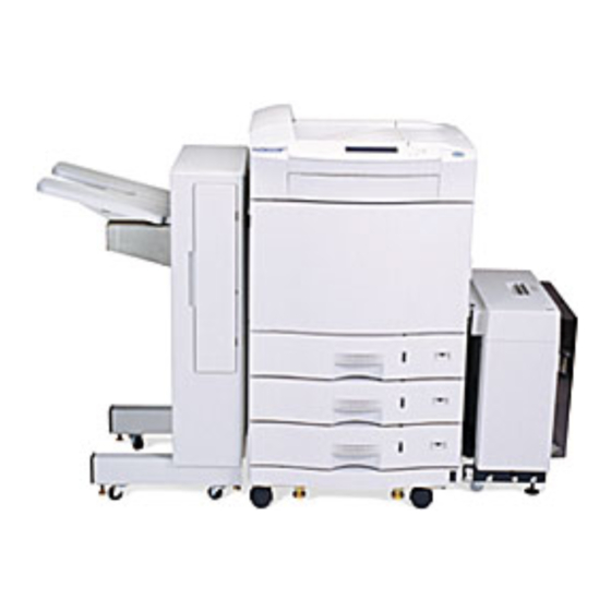
Sign In
Upload
Manuals
Brands
MINOLTA-QMS Manuals
Printer
4060
MINOLTA-QMS 4060 Manuals
Manuals and User Guides for MINOLTA-QMS 4060. We have
1
MINOLTA-QMS 4060 manual available for free PDF download: Service And Parts Manual
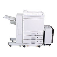
MINOLTA-QMS 4060 Service And Parts Manual (696 pages)
Brand:
MINOLTA-QMS
| Category:
Printer
| Size: 8.78 MB
Table of Contents
Table of Contents
3
Introduction
5
Printer Specifications
6
Printer Print Speed Specifications
6
Printer Physical Specifications
7
Printer Electrical Specifications
7
Environmental Specifications for All Equipment
9
Summary of Printer Optional Features and Feature Specifications
9
Large-Capacity Hopper (LCH)
11
LCH Overview
11
1-4.2 LCH Paper Handling Specifications
11
LCH Physical Specifications
12
LCH Electrical Specifications
13
LCH Environmental Specifications
13
Large-Capacity Stacker (LCS)
14
LCS Overview
14
LCS Paper Handling Specifications
14
LCS Physical Specifications
15
LCS Electrical Specifications
15
1-5.5 LCS Environmental Specifications
15
Printer Custom Paper Tray
16
Printer Consumable Specifications
16
Best Printing Area Specifications
18
System Configuration Component Locations and Descriptions
21
Front and Right Side of the Printer
21
Behind the Front Door
22
Behind the Upper Right Cover
24
1-9.4 Behind the Lower Right Cover
25
Rear and Left Side of the Printer
26
1-9.6 Rear-Inside of the Printer
28
1-9.7 Large-Capacity Hopper (LCH) Accessory
29
1-9.8 Large-Capacity Stacker (LCS) Accessory
30
1-10. Printer Component Block Diagram
31
1-11. Safety and Regulatory Information
35
1-12. Servicing Approach
35
Introduction
38
Overview of Printing Process
38
Mechanical Operation
38
Video Data Control
41
Developer Replacement
46
Paper Feed Operation
50
2-3.1 Operational Timing Charts
50
Printer Power
60
2-4.1 Low Voltage Power Supply Block Diagram
60
2-4.2 High Voltage Power Supply Block Diagram
62
Power-On Sequence Timing Chart
65
Troubleshooting Approach
81
General Troubleshooting Flow Chart
82
Alarm Error Message Reported Problems
84
SVC08 Upper Pick Motor Alarm
86
SVC09 Middle Pick Motor Alarm
88
SVC0A Lower Pick Motor Alarm
90
SVC0B Reversing Motor Alarm
92
SVC0D Feed Motor Alarm
94
SVC0E Stacker Select Solenoid Alarm
96
SVC0F Duplex Motor Alarm
98
SVC27 Fuser Time-Out Alarm
100
SVC28 Fuser High-Temperature Alarm
106
5-2.10. SVC29 Fuser Low-Temperature Alarm
110
5-2.11. SVC50 Toner Motor Alarm
116
5-2.12. SVC51 Toner Discharge Screw Alarm
118
5-2.13. SVC52 Developer Discharge Alarm
120
5-2.14. SVC54 Developer Discharge Shutter Alarm
126
5-2.15. SVC56 Automatic Adjustment Alarm
130
5-2.16. SVC57 Toner High-Density Alarm
136
5-2.17. SVC58 Toner Low-Density Alarm
142
5-2.18. SVC59 Reference Voltage Too-High Alarm
148
5-2.19. SVC5A Reference Voltage Too-Low Alarm
150
5-2.20. SVC5B Toner Hopper Alarm
152
5-2.21. SVC69 Main Motor Alarm
156
5-2.22. SVC6F High Voltage Power Alarm
162
5-2.23. SVC79 Spindle Motor Alarm
169
5-2.24. SVC7A BD1 (Beam Detection) Alarm
174
5-2.25. SVC7B BD2 (Beam Detection) Alarm
178
5-2.26. SVC7C Beam Detection High-Speed Alarm
182
5-2.27. SVC7D Beam Detection Low-Speed Alarm
186
5-2.28. SVC7E Laser Diode (LD) Alarm
190
5-2.29. SVCA0 Fan Alarm 1
194
SVCA1 Fan Alarm 2
201
SVCA5 Fan Alarm 6
205
SVCA6 Fan Alarm 7
211
SVCB0 Watchdog Timer Alarm-Master
214
SVCB1 Watchdog Timer Alarm-Slave
216
SVCB3 Mechanism Controller Communication Alarm
218
SVCB4 EEPROM Alarm
220
SVCB5 Video Synchronous (VS) Alarm
222
SVCB6 Pre-Pick Alarm
224
SVCB7 Video Request (VR) Alarm
226
Paper Jam Error Message Reported Problems
228
JAM01/02/03 Pick Error
228
5-3.2. JAM11/12/13 Feed Jam 1
234
JAM18 Feed Jam 2
240
JAM25 Fuser Unit Jam 1
244
5-3.5. JAM26/27 Fuser Unit Jam 2
258
JAM29 Ejection Unit Jam 1
264
5-3.7. JAM2B/2C Ejection Unit Jam 2
270
5-3.8. JAM31 Duplex Printing Path Jam 1
278
5-3.9. JAM32 Duplex Printing Path Jam 2
286
Power Related Problems
294
5-4.1. Cannot Power Printer Mechanism or Controls on
294
5-4.2. Control Powers on but Cannot Power Printer Mechanism on
304
5-4.3. Cannot Power off Printer with Stand-By Switch
318
Miscellaneous Problems
322
5-5.1. Operator Panel Symptoms
322
5-5.2. Cover Open / Interlock
324
5-5.3. Paper Tray Not Ready
330
5-5.4. out of Paper
332
Stacker Full Cannot be Cleared
336
5-5.6. Stacker Full Cannot be Detected
338
5-5.7. Developer Cannot Discharge Unless START Pressed
340
Print Quality Problems
344
5-6.1. General Approach to Print Quality Problems
346
5-6.2. Good Quality Print
348
5-6.3. Black or Dark Print
352
5-6.4. Blank Print
354
5-6.5. Blank Vertical Bands Print
358
5-6.6. Blurred Images or Blurred Characters Print
362
5-6.7. Dark-Specks, Dark-Lines, or Dark-Areas Print
366
5-6.8. Dark Vertical Lines Print
370
5-6.9. Fusing Problems Print
372
5-6.10. Light Print with Background
374
Light Horizontal Bands Print
380
Light Vertical Streaks Print
382
Misregistration Print
386
Residual Images Print
388
Skewed Print
392
Varying Print Density Print
394
Washed-Out Print
398
LCH Alarm Error Message Reported Problems
402
5-7.1. JAM51 LCH Pick Error
402
5-7.2. JAM52 LCH Feed Jam 1
410
JAM53 LCH Feed Jam 2
418
5-7.4. SVCC4 LCH Elevator Descent Alarm
420
5-7.5. SVCC5 LCH Elevator Ascent Alarm
424
LCH Miscellaneous Problems
428
LCH Sensing Problem 1
429
LCH Sensing Problem 2
430
LCS Alarm Error Message Reported Problems
432
5-9.1. JAM41 LCS Stacker Jam
435
5-9.2. SVCD8 LCS Stacker Alarm
446
5-10. LCS Miscellaneous Problems
459
5-10.1. LCS Stacker Full Related Problems
459
5-10.2. LCS Door Open Related Problems
468
5-10.3. LCS Stacker Tray Continuous Up-Down Travel
472
5-10.4. LCS Stacker Tray Stays down
474
5-10.5. LCS Not Sensed by Printer
476
5-10.6. LCS Not Installed but Sensed by Printer
478
Introduction
483
Scope of Repair Procedures
483
Safety
483
Maintenance Parts Replacement Overview
483
6-4.1 FRU Locational Views
484
6-4.2 FRU Repair Procedure Locations
485
Adjustments
496
6-5.1 +5V Power Supply Adjustment
496
6-5.2 Laser Start Position Alignment
498
6-5.3 Paper Feed System Alignment
500
Front of Printer Accessed Frus
502
6-6.1 Duplex Unit
502
6-6.2 LED Erase Unit
505
6-6.3 Operator Panel Board
509
6-6.4 Transfer Assembly Guide
513
6-6.5 Paper Tray Lift Motor
517
6-6.6 Paper Size Sensor Board
519
Top of Printer Accessed Frus
521
6-7.1 Main Controller Board
522
Optical Unit
526
Rear of Printer Accessed Frus
530
6-8.1 Drive Unit D Motor Assembly
531
6-8.2 Mechanism Controller Board
534
6-8.3 Registration Roller Standby Clutch
537
6-8.4 High Voltage Power Supply
539
Low Voltage Power Supply
541
6-8.6 Low Voltage Power Supply Fan
544
6-8.7 Power Sequencing Relay
546
Drive Unit M
548
6-8.9 Drive Unit M Lower Fan
558
6-8.10 Drive Unit M Waste Toner Screw Sensor
560
6-8.11 Drive Unit M Fuser Interlock Switch (TINTSW)
563
6-8.12 Drive Unit E to Ejection Unit Belt
566
6-8.13 Drive Unit E Gear Assembly
568
6-8.14 PS5 - Duplex Unit Paper Path Sensor
572
6-8.15 PS7 - Ejection Unit Paper Path Sensor
574
6-8.16 Ejection Tray - Paper Path Stacker Full Sensor
576
Left Side of Printer Accessed Frus
578
Ejection Unit
578
6-9.2 Reversing Unit
580
PS6 - Reversing Unit Paper Path Sensor
582
Right Side of Printer Accessed Frus
584
Toner Hopper Assembly
584
Input Power Circuit Breaker
586
Developer Unit
588
Paper Feed Unit
592
PS2 - Paper Path Timing Sensor
598
PS3 - Paper Path Registration Sensor
600
PS4 - Paper Path De-Curling Sensor
602
Paper Feed Unit Transport Feed Motor
606
Registration Roller
612
Printer Microswitch Locational Diagrams
614
Developer Unit Collector Bottle Detection Microswitch
614
Developer Unit Shutter Detection Microswitch
615
Ejection Unit Cover Interlock Microswitch
618
Front Door Interlock Microswitch
619
Paper Tray Detection Microswitch
620
Lower-Right Cover Interlock Microswitch
621
Upper-Right Cover Interlock Microswitch
622
Introduction
626
Understanding Parts List Heading Descriptions
626
Printer Parts Locational Diagrams and Listings
627
Cover Assemblies
627
Duplex Unit
630
Fuser and Drum Units
632
Transfer Assembly Guide
634
Main Controller and Optical Unit
638
Ejection Unit and Operator Panel
640
Reversing Unit
642
Paper Path Transport Assembly
644
Paper Feed Unit
646
Toner Hopper and Developer Units
648
Main Frame Assembly
650
Drive Unit M
652
Mechanism Controller PCB, HVPS, LVPS, and LVPS Fan
654
Drive Unit D Motor, Drive Unit E, and Drive Unit E Belt
656
LCIF Parts Locational Diagrams and Listings
658
LCIF Frame
658
Paper Feed Assembly
660
LCIF Paper Transport
662
LCOS Parts Locational Diagrams and Listings
666
LCOS Attachment Parts
666
LCOS Stacker Frame
668
LCOS Controls and Cover Assemblies
670
LCOS Input-Paper Transport Assembly
672
LCOS Output-Paper Transport Assembly
674
Advertisement
Advertisement
Related Products
MINOLTA-QMS PagePro 4100
MINOLTA-QMS PagePro 4100GN
MINOLTA-QMS PagePro 4100W
MINOLTA-QMS PagePro 4110W
MINOLTA-QMS PagePro 4100E
MINOLTA-QMS 4179-255
MINOLTA-QMS 2060
MINOLTA-QMS ENord magicolor 3100
MINOLTA-QMS Magicolor 2 Desklaser
MINOLTA-QMS Magicolor 2+
MINOLTA-QMS Categories
Printer
Software
Printer Accessories
All in One Printer
Remote Control
More MINOLTA-QMS Manuals
Login
Sign In
OR
Sign in with Facebook
Sign in with Google
Upload manual
Upload from disk
Upload from URL