Table of Contents
Advertisement
Quick Links
Advertisement
Table of Contents

Subscribe to Our Youtube Channel
Related Manuals for LifeSpan TR2000e


Summary of Contents for LifeSpan TR2000e
- Page 1 Owner’s Manual TR2000e \ TR3000e Electric Folding Treadmill...
- Page 2 Welcome Congratulations on Purchasing Your LifeSpan Treadmill! At LifeSpan we take pride in the quality, safety, and reliability of our products as well as the professionalism of our sales support and customer service teams. Making it our number one priority that you have an exceptional experience using our products.
-
Page 3: Table Of Contents
Contents About Your Treadmill ....................Specifications Unique Features Warranty Safety First ......................... Children and Pets Safety Tips Safety Key Proper Grounding Assembling Your Treadmill ................. Exploded View & Hardware Assembly Instructions Console Basics ......................Console Overview Readout Display Operating Keyboard Operations ........................ -
Page 4: About Your Treadmill
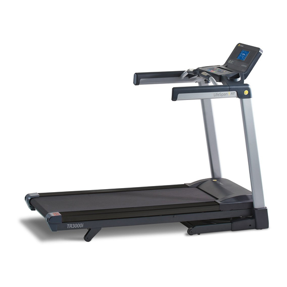
About Your Treadmill Specifications TR2000e Drive Motor 2.5 HP Continuous Duty Max User Weight 300 lb (136 kg) Heart Rate Contact Sensors / Chest Strap Compatible Speed Range 0.5 - 11 mph (0.8 - 18 kph) Running Belt Size 20” x 56” (51 cm x 142 cm) -
Page 5: Unique Features
About Your Treadmill Unique Features As a leader in the fitness industry, LifeSpan has developed a number of unique features in our treadmills making them more engaging, safer and easier to use. Learn more about how to use these features in the Personal Settings sections of this Owner’s Manual. -
Page 6: Warranty
In order to insure our product warranty and to ensure the safe and efficient operation of your LifeSpan product, only authorized parts can be used. The warranty is void if any parts other than those provided by LifeSpan are used. -
Page 7: Safety First
• Use this exercise product for its intended use as described in this Owner’s Manual. Do not use attachments that are not recommended by LifeSpan. • Do not leave your treadmill running while not in use. Children and Pets •... -
Page 8: Safety Tips
Safety First Safety Tips While in Use • Always consult a physician before beginning an exercise program. • If you experience chest pains, nausea, dizziness or shortness of breath, stop exercising immediately and consult your physician before continuing. Do not wear clothing or jewelry that might catch on any part of the treadmill. -
Page 9: Safety Key
Safety First Safety Key The safety key is required to operate this treadmill. With the safety key installed the treadmill is operational. With the safety key pulled, power is turned off to the motor making the treadmill inoperable. Securely attach safety key clip in case of a fall Insert safety key... -
Page 10: Proper Grounding
Power Cord Options This treadmill should only be used with the proper power cord and power outlet. Several power cord options (shown below) are available from LifeSpan. We do our best do include the correct power cord with the treadmill for your area. -
Page 11: Assembling Your Treadmill
Assembling Your Treadmill Exploded View Prior to starting the assembly process take all of the parts out of the box. Remove plastic bags and lay them out on the floor to become familiar with the components. Since your treadmill is a heavy piece of equipment it is recommended you use two people during assembly and follow these assembly instructions to reduce any problems that could occur. - Page 12 Assembling Your Treadmill Hardware Included Item# Part Description Right Upright Post Left Upright Post Right Upright Post Cover Left Upright Post Cover Console Right Cup Holder Left Cup Holder Hardware Bag Contents Item # Qty. Hardware Description 6mm Allen Wrench 5mm Allen Wrench with Phillips Screw Driver M10 x 45L Bolt - (Upright Attachment) M10 Washer - (Upright Attachment)
- Page 13 Assembling Your Treadmill Step 1: Unpacking Treadmill Cut packaging straps and remove. Remove the box top. Remove small parts and packaging material and unwrap parts. Cut the corners of the bottom box and remove all packaging material to begin assembly. The treadmill can be assembled in the box. No need to pick the treadmill up to remove it from box.
- Page 14 Assembling Your Treadmill Step 3: Upright Post Cover Attachment Remove pre-installed M4x8L Screw (13). Install the Left Upright Cover (4) by sliding the front of the cover around the upright and centering or aligning the cover on the upright. 5mm Allen M4 x 8L Wrench w/ (x4)
- Page 15 Assembling Your Treadmill Step 5: Console Harness Attachment A. Slide the square mounting tubes (protruding from the front of the Console (5)) partially into the console mount as shown in the figure to the left. Do not slide the console all the way in as wire connections need to be made.
- Page 16 Assembling Your Treadmill Securely attach the seven remaining cable connectors – There are four 2-pin, two 3-pin and one 10-pin connector that will need to be connected. 1. Attach the 10-pin connectors (7-pin connectors) together (C1) . 2. Attach the wires labeled “SK” together (C2). 3.
- Page 17 Assembling Your Treadmill View From Beneath Pre-installed 6mm Allen M8 x 15L Wrench (x4) Step 6: Securing Console Slide the console fully into the mounting brackets. If the console does not want to slide in completely, loosen the four pre-installed M8 x 15L Bolts (14) with the provided 6mm Allen wrench to eliminate any friction.
- Page 18 Assembling Your Treadmill Place the Right Cup Holder (6) over the handlebar and into the frame as shown. Loosely install the two screws removed in step A. Once both screws are installed, securely tighten both screws. Repeat steps A through C for installing the Left Cup Holder (7) M4 x 8L...
-
Page 19: Console Basics
Console Basics Console Overview USB Plus Power Button Audio Input Cooling Fan Safety Key... - Page 20 Console Basics Display Speakers eFold Control Media Holders Keyboard...
Need help?
Do you have a question about the TR2000e and is the answer not in the manual?
Questions and answers