
Related Manuals for turck TBEN-LL Series


Summary of Contents for turck TBEN-LL Series
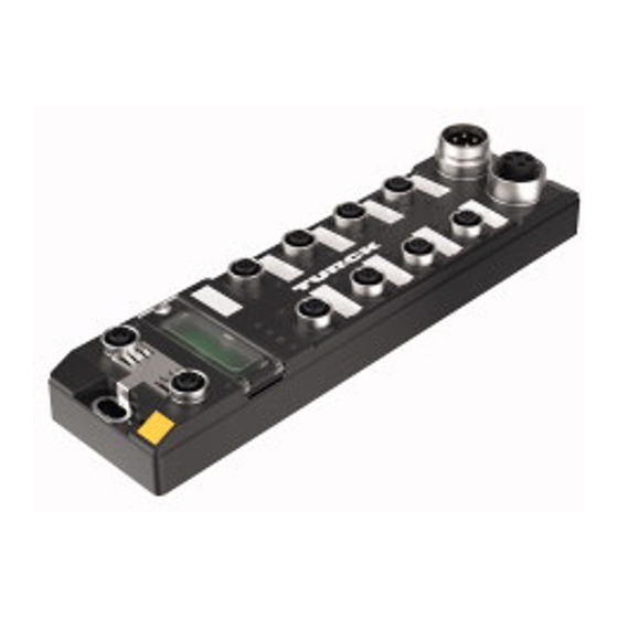
- Page 1 Your Global Automation Partner TBEN-LL-… Digital I/O Modules Instructions for Use...
-
Page 2: Table Of Contents
Connecting the device to Ethernet ................ 18 6.3.1 QuickConnect and Fast Start-Up applications.............. 18 Connecting the power supply .................. 19 6.4.1 Supply concept .......................... 20 V01.00 | 2022/10 | 2 Hans Turck GmbH & Co. KG | T +49 208 4952-0 | more@turck.com | www.turck.com... - Page 3 Configuring the device in RS Logix.................. 87 7.8.3 Parameterizing the device ...................... 88 7.8.4 Going online with the PLC ...................... 89 7.8.5 Reading process data........................ 91 V01.00 | 2022/10 | 3 Hans Turck GmbH & Co. KG | T +49 208 4952-0 | more@turck.com | www.turck.com...
- Page 4 15 Appendix: approvals and markings ................... 115 15.1 ATEX, IECEx and UKEX.................... 115 16 Turck subsidiaries — contact information................ 116 V01.00 | 2022/10 | 4 Hans Turck GmbH & Co. KG | T +49 208 4952-0 | more@turck.com | www.turck.com...
-
Page 5: About These Instructions
If you have any suggestions for improving the design or if some information is missing in the document, please send your suggestions to techdoc@turck.com. V01.00 | 2022/10 | 5 Hans Turck GmbH & Co. KG | T +49 208 4952-0 | more@turck.com | www.turck.com... -
Page 6: Notes On The Product
Screw caps or blind caps for network and I/O connectors Labeling clips Turck service Turck supports you with your projects, from initial analysis to the commissioning of your applic- ation. The Turck product database under www.turck.com contains software tools for program- ming, configuration or commissioning, data sheets and CAD files in numerous export formats. -
Page 7: For Your Safety
The product is designed according to state-of-the-art technology. However, residual risks still exist. Observe the following warnings and safety notices to prevent damage to persons and property. Turck accepts no liability for damage caused by failure to observe these warning and safety notices. -
Page 8: Ex Approval Requirements For Use In Ex Area
Seal unused connectors with dummy plugs to ensure the degrees of protection IP65, IP67 or IP69K. The tightening torque for the screw caps is 0.5 Nm. V01.00 | 2022/10 | 8 Hans Turck GmbH & Co. KG | T +49 208 4952-0 | more@turck.com | www.turck.com... -
Page 9: Product Description
The device has the following operating elements: Rotary coding switches for adjusting the network settings Reset button for executing a device restart V01.00 | 2022/10 | 9 Hans Turck GmbH & Co. KG | T +49 208 4952-0 | more@turck.com | www.turck.com... -
Page 10: Properties And Features
– Network load class 3 EtherNet/IP: – Support of the IO-Link Parameter Object for asynchronous services (IO-Link CALL) – Predefined in- and oputput assemblies V01.00 | 2022/10 | 10 Hans Turck GmbH & Co. KG | T +49 208 4952-0 | more@turck.com | www.turck.com... -
Page 11: Functions And Operating Modes
FSU (fast startup) Topology detection Address allocation with LLDP Media redundancy protocol (MRP) EtherNet/IP QC (QuickConnect) Device Level Ring (DLR) V01.00 | 2022/10 | 11 Hans Turck GmbH & Co. KG | T +49 208 4952-0 | more@turck.com | www.turck.com... -
Page 12: Digital Modules - Extended Digital Functions
The ARGEE-FLC programming software can be downloaded free of charge from www.turck.com. The Zip archive SW_ARGEE_Environment_Vx.x.zip also contains the documentation for the pro- gramming environment in addition to the software. V01.00 | 2022/10 | 12 Hans Turck GmbH & Co. KG | T +49 208 4952-0 | more@turck.com | www.turck.com... -
Page 13: Installing
Mount and screw the housing cover according to the following figure. The tightening torque for the Torx T8 screw is 0.5 Nm. Fig. 2: Mounting the device in protection housing TB-SG-L V01.00 | 2022/10 | 13 Hans Turck GmbH & Co. KG | T +49 208 4952-0 | more@turck.com | www.turck.com... -
Page 14: Mounting Onto A Mounting Plate
„ To avoid material abrasion and color changes: Protect the device from direct sunlight, e.g. by using protective shields. V01.00 | 2022/10 | 14 Hans Turck GmbH & Co. KG | T +49 208 4952-0 | more@turck.com | www.turck.com... -
Page 15: Grounding The Device
RC element, the grounding clip must be removed. In the delivery state, the grounding clip is mounted. V01.00 | 2022/10 | 15 Hans Turck GmbH & Co. KG | T +49 208 4952-0 | more@turck.com | www.turck.com... -
Page 16: Disconnecting The Direct Grounding Of The Fieldbus Level: Removing The Grounding Clip
With mounted grounding clip: The shielding of the fieldbus and the module grounding are connected to the reference potential of the installation. V01.00 | 2022/10 | 16 Hans Turck GmbH & Co. KG | T +49 208 4952-0 | more@turck.com | www.turck.com... -
Page 17: Connecting
„ Always seal unused connectors with suitable screw caps or blind caps. The tight- ening torque for the screw caps is 0.5 Nm. V01.00 | 2022/10 | 17 Hans Turck GmbH & Co. KG | T +49 208 4952-0 | more@turck.com | www.turck.com... -
Page 18: Connecting The Device To Ethernet
Do not use crossover cables in QuickConnect and Fast Start-Up applications. „ Connect incoming Ethernet cables to XF1. „ Connect outgoing Ethernet cables to XF2. V01.00 | 2022/10 | 18 Hans Turck GmbH & Co. KG | T +49 208 4952-0 | more@turck.com | www.turck.com... -
Page 19: Connecting The Power Supply
PWR LED changes from green to green flashing or red (depending on the configuration). If V1 is undershot, the PWR LED extinguishes. V01.00 | 2022/10 | 19 Hans Turck GmbH & Co. KG | T +49 208 4952-0 | more@turck.com | www.turck.com... -
Page 20: Supply Concept
V2 supply. Fig. 12: Power supply of TBEN-LL-16DIP Fig. 13: Power supply of TBEN-LL-16DXP and TBEN-LL-8DIP-8DOP Fig. 14: Power supply of TBEN-LL-16DOP V01.00 | 2022/10 | 20 Hans Turck GmbH & Co. KG | T +49 208 4952-0 | more@turck.com | www.turck.com... -
Page 21: Connecting Digital Sensors And Actuators
5 FE 4 BK 1 BN + 2 WH 3 BU – X0…X7 Fig. 17: Connectors for digital sensors – wiring diagram V01.00 | 2022/10 | 21 Hans Turck GmbH & Co. KG | T +49 208 4952-0 | more@turck.com | www.turck.com... -
Page 22: Tben-Ll-16Dop
5 FE 4 BK 1 BN + 2 WH 3 BU – X0…X3 Fig. 21: Connectors for digital sensors – wiring diagram V01.00 | 2022/10 | 22 Hans Turck GmbH & Co. KG | T +49 208 4952-0 | more@turck.com | www.turck.com... -
Page 23: Tben-Ll-16Dxp
1 BN + Sensor 2 WH 3 BU – Actuator X0...X7 Fig. 26: Connectors for digital sensors and actuators – wiring diagram V01.00 | 2022/10 | 23 Hans Turck GmbH & Co. KG | T +49 208 4952-0 | more@turck.com | www.turck.com... -
Page 24: Commissioning
In the safe state, the VAUX2 supply and the outputs supplied via V2 are voltage-free. The load voltage is switched off externally in the higher-level system via an external safety relay or a safety control system. V01.00 | 2022/10 | 24 Hans Turck GmbH & Co. KG | T +49 208 4952-0 | more@turck.com | www.turck.com... -
Page 25: Safety Planning
„ If the galvanic isolation is used, ensure on the application side that no external feed can occur. „ DXP channels that operate with safe disconnectable potential must be supplied by the corresponding conenctor. V01.00 | 2022/10 | 25 Hans Turck GmbH & Co. KG | T +49 208 4952-0 | more@turck.com | www.turck.com... -
Page 26: Adjusting Network Settings
The subnet mask assigned by the BootP server and the default gateway address are stored non-volatile in the memory of the device. V01.00 | 2022/10 | 26 Hans Turck GmbH & Co. KG | T +49 208 4952-0 | more@turck.com | www.turck.com... - Page 27 The factory reset resets all settings to the default values: Network setting (IP address, subnet mask, gateway) PROFINET device name Device parameters V01.00 | 2022/10 | 27 Hans Turck GmbH & Co. KG | T +49 208 4952-0 | more@turck.com | www.turck.com...
-
Page 28: Adjusting Network Setting Via Turck Service Tool
Fig. 28: Turck Service Tool: start screen Turck Service Tool shows the devices found. Fig. 29: Turck Service Tool – found devices V01.00 | 2022/10 | 28 Hans Turck GmbH & Co. KG | T +49 208 4952-0 | more@turck.com | www.turck.com... - Page 29 Change the IP address and the network mask if necessary. „ Accept the changes with Set in device. Fig. 31: Turck Service Tool – change device configuration V01.00 | 2022/10 | 29 Hans Turck GmbH & Co. KG | T +49 208 4952-0 | more@turck.com | www.turck.com...
-
Page 30: Adjusting Network Settings Via The Web Server
Adjust the network settings. „ Write the changes into the device via Submit. Fig. 32: Adjusting network settings via the web server V01.00 | 2022/10 | 30 Hans Turck GmbH & Co. KG | T +49 208 4952-0 | more@turck.com | www.turck.com... -
Page 31: Commissioning The Device In Profinet
For the correct cabling in FSU applications please observe the note in the chapter "Connecting the Device to Ethernet” [} 18] . Fast Start-Up TBEN Turck TBEN-L devices support the prioritized start-up (FSU). In order to enable FSU, the field bus nodes have to be configured respectively , for example in TIA-Portal (Siemens). Autonegotiation... - Page 32 Commissioning Commissioning the device in PROFINET „ Deactivate auto-negotiation Fig. 33: TIA-Portal – port-settings for FSU V01.00 | 2022/10 | 32 Hans Turck GmbH & Co. KG | T +49 208 4952-0 | more@turck.com | www.turck.com...
-
Page 33: Mrp (Media Redundancy Protocol)
For PROFINET, the response monitoring time must be selected accordingly > 200 ms. It is not possible to use Fast Start-Up in an MRP network. V01.00 | 2022/10 | 33 Hans Turck GmbH & Co. KG | T +49 208 4952-0 | more@turck.com | www.turck.com... -
Page 34: User Data For Acyclic Services
0xAFEF 45040 0xAFF0 I&M0-functions read Identification & Maintaining 45041 0xAFF1 I&M0-functions STRING read/ I&M Tag function and [54] write location V01.00 | 2022/10 | 34 Hans Turck GmbH & Co. KG | T +49 208 4952-0 | more@turck.com | www.turck.com... - Page 35 45044 0xAFF4 I&M4-functions STRING read/ I&M Signature [54] write 45045… 0xAFF5 I&M5 to I&M15- not supported 45055 … functions 0xAFFF V01.00 | 2022/10 | 35 Hans Turck GmbH & Co. KG | T +49 208 4952-0 | more@turck.com | www.turck.com...
-
Page 36: Connecting The Devices To A Profinet Master With Tia Portal
Installing the GSDML-file: Define the source path for the GSDML-file and click Install. The device is added to the Hardware catalog of the programming software. Fig. 35: Installing the GSDML-file V01.00 | 2022/10 | 36 Hans Turck GmbH & Co. KG | T +49 208 4952-0 | more@turck.com | www.turck.com... -
Page 37: Connecting The Device To The Plc
„ Connect the devices to the PLC in the Devices & networks editor. Fig. 36: Connecting the device to the PLC V01.00 | 2022/10 | 37 Hans Turck GmbH & Co. KG | T +49 208 4952-0 | more@turck.com | www.turck.com... -
Page 38: Assigning The Profinet Device Name
Assign PROFINET device name. „ Assign the desired PROFINET device name with Assign name. Fig. 37: TIA-Portal – assigning the PROFINET device name V01.00 | 2022/10 | 38 Hans Turck GmbH & Co. KG | T +49 208 4952-0 | more@turck.com | www.turck.com... -
Page 39: Setting The Ip Address In Tia Portal
„ Select Device Properties tab Ethernet addresses. „ Assign the desired IP address. Fig. 38: TIA-Portal – Assigning the IP address V01.00 | 2022/10 | 39 Hans Turck GmbH & Co. KG | T +49 208 4952-0 | more@turck.com | www.turck.com... -
Page 40: Setting Module Parameters
Select the device to be parameterized. Ò Ò „ Click Properties General Module parameters. „ Set the device parameters. Fig. 39: Setting Module Parameters V01.00 | 2022/10 | 40 Hans Turck GmbH & Co. KG | T +49 208 4952-0 | more@turck.com | www.turck.com... -
Page 41: Connecting The Device Online With The Controller
Start the online mode (Go online). The device has been successfully connected to the PLC. Fig. 40: TIA-Portal – Online mode V01.00 | 2022/10 | 41 Hans Turck GmbH & Co. KG | T +49 208 4952-0 | more@turck.com | www.turck.com... -
Page 42: Commissioning The Device In Modbus Tcp
1 = green flashing 0x2400 read only V1 in mV: 0 at undervoltage 0x2401 read only V2 in mV: 0 at undervoltage V01.00 | 2022/10 | 42 Hans Turck GmbH & Co. KG | T +49 208 4952-0 | more@turck.com | www.turck.com... - Page 43 Process data of the inputs (identical to registers 0x0000… 0x01FF) 0x8400 0x9000… read/write Process data of the outputs (identical to registers 0x0800…0x09FF) 0x9400 V01.00 | 2022/10 | 43 Hans Turck GmbH & Co. KG | T +49 208 4952-0 | more@turck.com | www.turck.com...
-
Page 44: Data Width Of The I/O-Modules
16 bit Bit by bit TBEN-LL-16DXP 16 bit 16 bit Bit by bit TBEN-LL-8DIP-8DOP 8 bit 8 bit Bit by bit V01.00 | 2022/10 | 44 Hans Turck GmbH & Co. KG | T +49 208 4952-0 | more@turck.com | www.turck.com... -
Page 45: Error Behavior (Watchdog)
”0” after the watchdog time has expired, unless another protocol (PROFINET, Eth- erNet/IP) has been activated in the meantime. V01.00 | 2022/10 | 45 Hans Turck GmbH & Co. KG | T +49 208 4952-0 | more@turck.com | www.turck.com... -
Page 46: Register Mapping Of The Devices
DI15 DI14 DI13 DI12 DI11 DI10 0xB001 IST DI1 IST DI0 … 0xB008 IST DI15 IST DI14 0xB009 reserved reserved V01.00 | 2022/10 | 46 Hans Turck GmbH & Co. KG | T +49 208 4952-0 | more@turck.com | www.turck.com... - Page 47 ERR4 ERR3 ERR2 ERR1 ERR0 TBEN-LL-16DOP – parameter registers Register Bit no. 0xB000 SRO DO15 DO14 DO13 DO12 DO11 DO10 V01.00 | 2022/10 | 47 Hans Turck GmbH & Co. KG | T +49 208 4952-0 | more@turck.com | www.turck.com...
- Page 48 Inv. DI15 DI14 DI13 DI12 DI11 DI10 0xB003 IST DI1 IST DI0 … 0xB00A IST DI15 IST DI14 0xB00B Reserved V01.00 | 2022/10 | 48 Hans Turck GmbH & Co. KG | T +49 208 4952-0 | more@turck.com | www.turck.com...
- Page 49 Inv. Inv. Inv. Inv. Inv. Inv. Inv. 0xB002 IST DI1 IST DI0 … 0xB005 IST DI7 IST DI6 0xB006 reserved V01.00 | 2022/10 | 49 Hans Turck GmbH & Co. KG | T +49 208 4952-0 | more@turck.com | www.turck.com...
- Page 50 Overcurrent output VERR V1 X… K… Overcurrent supply VAUX1 VERR V2 P1 X… K… Overcurrent supply VAUX2 at pin 1 V01.00 | 2022/10 | 50 Hans Turck GmbH & Co. KG | T +49 208 4952-0 | more@turck.com | www.turck.com...
-
Page 51: Connecting Devices To A Modbus Master With Codesys
The following components have to be added to CODESYS first, in order to connect the device to the PLC. Ethernet Adapter Modbus TCP Master Modbus TCP Slave V01.00 | 2022/10 | 51 Hans Turck GmbH & Co. KG | T +49 208 4952-0 | more@turck.com | www.turck.com... - Page 52 Click Add Device. The Ethernet Adapter is added to the project tree as Ethernet (Ethernet). Fig. 41: Adding the Ethernet Adapter V01.00 | 2022/10 | 52 Hans Turck GmbH & Co. KG | T +49 208 4952-0 | more@turck.com | www.turck.com...
- Page 53 Double-click Modbus TCP Master. The Modbus Master is added to the project tree as Modbus_TCP_Master. Fig. 42: Adding the Modbus Master V01.00 | 2022/10 | 53 Hans Turck GmbH & Co. KG | T +49 208 4952-0 | more@turck.com | www.turck.com...
- Page 54 Double-click the Modbus TCP Slave. The Modbus Slave is added to the project tree as Modbus_TCP_Slave. Fig. 43: Adding a Modbus Slave V01.00 | 2022/10 | 54 Hans Turck GmbH & Co. KG | T +49 208 4952-0 | more@turck.com | www.turck.com...
-
Page 55: Configuring The Network Interface
Scan Network. „ Modbus Master (here: TX715-P3CV01) and confirm with OK. Fig. 44: Configuring the Network Interface to the Modbus Master V01.00 | 2022/10 | 55 Hans Turck GmbH & Co. KG | T +49 208 4952-0 | more@turck.com | www.turck.com... - Page 56 Open the dialog box Network Adapter by clicking the … button in the register tab Gen- eral. „ Select the interface of the TX715 (here: 192.168.145.72). Fig. 45: Modbus-Master – selecting the interface V01.00 | 2022/10 | 56 Hans Turck GmbH & Co. KG | T +49 208 4952-0 | more@turck.com | www.turck.com...
-
Page 57: Modbus Tcp-Slave - Configuring The Ip Address
Enter the slave's IP address in the General register tab (here: 192.168.145.200). Fig. 46: Modbus TCP-Slave – configuring the IP address V01.00 | 2022/10 | 57 Hans Turck GmbH & Co. KG | T +49 208 4952-0 | more@turck.com | www.turck.com... -
Page 58: Defining Modbus Channels
Channel name Access type: Read Input Registers Offset: 0x0000 Length: 1 register „ Confirm with OK. Fig. 47: Defining the input register V01.00 | 2022/10 | 58 Hans Turck GmbH & Co. KG | T +49 208 4952-0 | more@turck.com | www.turck.com... - Page 59 Channel name Access type: Write Singe Register Offset: 0x0000 Length: 1 register „ Confirm with OK. Fig. 48: Defining the output register V01.00 | 2022/10 | 59 Hans Turck GmbH & Co. KG | T +49 208 4952-0 | more@turck.com | www.turck.com...
-
Page 60: Going Online With The Plc
Download the application to the PLC and start it via Debug Start. The Modbus TCP communication is setup. Fig. 50: Modbus TCP communication V01.00 | 2022/10 | 60 Hans Turck GmbH & Co. KG | T +49 208 4952-0 | more@turck.com | www.turck.com... -
Page 61: Reading Process Data
Click the register tab ModbusTCP Slave I/O Mapping. „ Set the function Always update variables to Enabled 1(…). The process data are displayed. Fig. 51: Process data V01.00 | 2022/10 | 61 Hans Turck GmbH & Co. KG | T +49 208 4952-0 | more@turck.com | www.turck.com... -
Page 62: Commissioning The Device In Ethernet/Ip
Full duplex Topology Linear AutoMDIX Deactivated Please read chapter [} 18] for more information about the correct Ethernet-cabling in QC-ap- plications. V01.00 | 2022/10 | 62 Hans Turck GmbH & Co. KG | T +49 208 4952-0 | more@turck.com | www.turck.com... - Page 63 Activate Quick Connect via Class Instance Attribute as follows: Class Instance Attribute Value 0xF5 0x01 0x0C 0: deactivated (default) 1: activated V01.00 | 2022/10 | 63 Hans Turck GmbH & Co. KG | T +49 208 4952-0 | more@turck.com | www.turck.com...
-
Page 64: Device Level Ring (Dlr)
V01.00 | 2022/10 | 64 Hans Turck GmbH & Co. KG | T +49 208 4952-0 | more@turck.com | www.turck.com... -
Page 65: Diagnostic Messages Via Process Data
Contains the last 3 bytes of the number MAC ID 0x07 Product STRUCT OF: i. e.: TBEN-LL-16DXP name USINT STRING [13] V01.00 | 2022/10 | 65 Hans Turck GmbH & Co. KG | T +49 208 4952-0 | more@turck.com | www.turck.com... - Page 66 Starts the reset service for the device 0x0E Get_Attribute_Single Returns the content of a specified attribute. 0x10 Set_Attribute_Single Modifies a single attribute V01.00 | 2022/10 | 66 Hans Turck GmbH & Co. KG | T +49 208 4952-0 | more@turck.com | www.turck.com...
- Page 67 Dec. Hex. 0x01 Get_Attribute_All Returns a predefined list of object attributes. 0x0E Get_Attribute_Single Returns the content of a specified attribute. V01.00 | 2022/10 | 67 Hans Turck GmbH & Co. KG | T +49 208 4952-0 | more@turck.com | www.turck.com...
- Page 68 0x18 Inv. DI14 0x19 Inv. DI15 0x1A IST DI0 0x1B IST DI1 … … 0x28 IST DI14 0x29 IST DI15 V01.00 | 2022/10 | 68 Hans Turck GmbH & Co. KG | T +49 208 4952-0 | more@turck.com | www.turck.com...
- Page 69 EN DO1 … … 0x38 EN DO14 0x39 EN DO15 0x3A SRO0 0x3B SRO1 … … 0x48 SRO14 0x49 SRO15 V01.00 | 2022/10 | 69 Hans Turck GmbH & Co. KG | T +49 208 4952-0 | more@turck.com | www.turck.com...
- Page 70 Eth1 port Quick 0x09 setup setup Connect Parameter data [} 92] 0x0A SRO8 0x0B SRO9 … … 0x18 SRO14 0x19 SRO15 V01.00 | 2022/10 | 70 Hans Turck GmbH & Co. KG | T +49 208 4952-0 | more@turck.com | www.turck.com...
- Page 71 2 bytes Output Assembly Instance 104 Device Output data TBEN-LL-16DIP 2 bytes TBEN-LL-16DXP 4 bytes TBEN-LL-8DIP-8DOP 4 bytes TBEN-LL-16DOP 4 bytes V01.00 | 2022/10 | 71 Hans Turck GmbH & Co. KG | T +49 208 4952-0 | more@turck.com | www.turck.com...
- Page 72 V1 X0 Ch14 Ch12 Ch10 Ch15 Ch13 Ch11 Output data – TBEN-LL-16DIP control word Word Bit no. Control 0x0000 Reserved V01.00 | 2022/10 | 72 Hans Turck GmbH & Co. KG | T +49 208 4952-0 | more@turck.com | www.turck.com...
- Page 73 DO13 DO12 DO11 DO10 X7P2 X7P4 X6P2 X6P4 X5P2 X5P4 X4P2 X4P4 X3P2 X3P4 X2P2 X2P4 X1P2 X1P4 X0P2 X0P4 V01.00 | 2022/10 | 73 Hans Turck GmbH & Co. KG | T +49 208 4952-0 | more@turck.com | www.turck.com...
- Page 74 DO13 DO12 DO11 DO10 X7P2 X7P4 X6P2 X6P4 X5P2 X5P4 X4P2 X4P4 X3P2 X3P4 X2P2 X2P4 X1P2 X1P4 X0P2 X0P4 V01.00 | 2022/10 | 74 Hans Turck GmbH & Co. KG | T +49 208 4952-0 | more@turck.com | www.turck.com...
- Page 75 Physical STRUCT link object Path size UINT Number of 16 bit words: 0x02 Path Padded 0x20, 0xF6, 0x24, 0x01 EPATH V01.00 | 2022/10 | 75 Hans Turck GmbH & Co. KG | T +49 208 4952-0 | more@turck.com | www.turck.com...
- Page 76 The device is capable of resolving host names by querying a DNS server. DHCP client The device is capable of obtaining its network configuration via DHCP. V01.00 | 2022/10 | 76 Hans Turck GmbH & Co. KG | T +49 208 4952-0 | more@turck.com | www.turck.com...
- Page 77 0x02 Max. object instance UINT 0x03 Number of instances UINT 0x06 Max. class identifier UINT 0x07 Max. instance attribute UINT V01.00 | 2022/10 | 77 Hans Turck GmbH & Co. KG | T +49 208 4952-0 | more@turck.com | www.turck.com...
- Page 78 1 = local hardware error detected Common services Service code Class Instance Meaning Dec. Hex. 0x01 Get_Attribute_All 0x0E Get_Attribute_Single 0x4C Enetlink_Get_and_Clear V01.00 | 2022/10 | 78 Hans Turck GmbH & Co. KG | T +49 208 4952-0 | more@turck.com | www.turck.com...
-
Page 79: Vsc-Vendor Specific Classes
USINT 0: No curr. 1: Yes 0x18 DO 15 – manual reset after over- USINT 0: No curr. 1: Yes V01.00 | 2022/10 | 79 Hans Turck GmbH & Co. KG | T +49 208 4952-0 | more@turck.com | www.turck.com... - Page 80 Bit 0: output value Ch0 Bit 1: output value Ch1 … Bit 6: output value Ch6 Bit 7: output value Ch7 V01.00 | 2022/10 | 80 Hans Turck GmbH & Co. KG | T +49 208 4952-0 | more@turck.com | www.turck.com...
- Page 81 Bit 0: input value Ch0 Bit 1: input value Ch1 …Bit 14: input value Ch14 Bit 15: input value Ch15 V01.00 | 2022/10 | 81 Hans Turck GmbH & Co. KG | T +49 208 4952-0 | more@turck.com | www.turck.com...
- Page 82 Bit 0: output value Ch0 Bit 1: output value Ch1 … Bit 14: output value Ch14 Bit 15: output value Ch15 V01.00 | 2022/10 | 82 Hans Turck GmbH & Co. KG | T +49 208 4952-0 | more@turck.com | www.turck.com...
- Page 83 DXP 0 – Overcurrent output USINT 0: - 1: active 0x42 DXP 1 – Overcurrent output USINT 0: - 1: active … … … V01.00 | 2022/10 | 83 Hans Turck GmbH & Co. KG | T +49 208 4952-0 | more@turck.com | www.turck.com...
- Page 84 Bit 0: output value Ch0 Bit 1: output value Ch1 … Bit 14: output value Ch14 Bit 15: output value Ch15 V01.00 | 2022/10 | 84 Hans Turck GmbH & Co. KG | T +49 208 4952-0 | more@turck.com | www.turck.com...
-
Page 85: Connecting The Devices To An Ethernet/Ip Scanner With Studio 5000
Adding the devices from the Catalog files to the new project „ Right-click the device entry and use Copy. Fig. 54: RSLogix – copying the device entry from catalog file V01.00 | 2022/10 | 85 Hans Turck GmbH & Co. KG | T +49 208 4952-0 | more@turck.com | www.turck.com... - Page 86 Right-click the EtherNet/IP-Scanner in the 2nd instance of the RS Logix and add the device to the project via Paste. Fig. 55: RS Logix - adding the device to the project V01.00 | 2022/10 | 86 Hans Turck GmbH & Co. KG | T +49 208 4952-0 | more@turck.com | www.turck.com...
-
Page 87: Configuring The Device In Rs Logix
Set the IP address of the device (example: 192.168.145.181). Fig. 56: Setting module name and IP address „ Optional: Set the connection parameters. Fig. 57: Setting the connection parameters V01.00 | 2022/10 | 87 Hans Turck GmbH & Co. KG | T +49 208 4952-0 | more@turck.com | www.turck.com... -
Page 88: Parameterizing The Device
Open the Controller Tags of the device. „ Parameterize the device via the Controller Tags TBEN_LL_16DXP:C. Fig. 58: Parameterizing the device V01.00 | 2022/10 | 88 Hans Turck GmbH & Co. KG | T +49 208 4952-0 | more@turck.com | www.turck.com... -
Page 89: Going Online With The Plc
Select the PLC. „ Set the communication path via Set Project Path. The communication path is set. Fig. 59: Setting the communication path V01.00 | 2022/10 | 89 Hans Turck GmbH & Co. KG | T +49 208 4952-0 | more@turck.com | www.turck.com... - Page 90 Click Download In the following dialog (Connect To Go Online) „ Confirm all following messages. The project is loaded down to the controller. The connection is established. V01.00 | 2022/10 | 90 Hans Turck GmbH & Co. KG | T +49 208 4952-0 | more@turck.com | www.turck.com...
-
Page 91: Reading Process Data
The access to the input data (TBEN_LL_16DXP:I) and output data (TBEN_LL_16DXP:O) is possible. Fig. 61: Controller Tags in the project tree V01.00 | 2022/10 | 91 Hans Turck GmbH & Co. KG | T +49 208 4952-0 | more@turck.com | www.turck.com... -
Page 92: Parameterizing And Configuring
0x02 The 24 VDC sensor/actuator supply at pin1 of the connector is switched off. V01.00 | 2022/10 | 92 Hans Turck GmbH & Co. KG | T +49 208 4952-0 | more@turck.com | www.turck.com... -
Page 93: Profinet Parameters
Deactivate EtherNet/IP Explicit disabling of the Ethernet pro- tocols or the web server Deactivate Modbus TCP Deactivate web server V01.00 | 2022/10 | 93 Hans Turck GmbH & Co. KG | T +49 208 4952-0 | more@turck.com | www.turck.com... -
Page 94: Operating
ERR14 ERR13 ERR12 ERR11 ERR10 ERR9 ERR8 Module status (device status) 0x3 0 0x00 - res. 0x01 V2 ARGEE DIAG V01.00 | 2022/10 | 94 Hans Turck GmbH & Co. KG | T +49 208 4952-0 | more@turck.com | www.turck.com... - Page 95 ARGEE program running in the device DIAG Diagnostic messages at the device Force Mode activated V1 too low V2 too low V01.00 | 2022/10 | 95 Hans Turck GmbH & Co. KG | T +49 208 4952-0 | more@turck.com | www.turck.com...
-
Page 96: Process Output Data
X7P4 X6P2 X6P4 X5P2 X5P4 X4P2 X4P4 0x01 Reserved Name Meaning DO… Digital output DX… DXP channel P… X… Connector V01.00 | 2022/10 | 96 Hans Turck GmbH & Co. KG | T +49 208 4952-0 | more@turck.com | www.turck.com... -
Page 97: Led Displays
Overload of the sensor and actuator supply In devices with group diagnostics, all connector LEDs of the supply group flash simultaneously in case of an error. V01.00 | 2022/10 | 97 Hans Turck GmbH & Co. KG | T +49 208 4952-0 | more@turck.com | www.turck.com... -
Page 98: Software Diagnostic Messages
Activating or deactivating the status and control word modifies the process data mapping. Control Word The control word has no function. V01.00 | 2022/10 | 98 Hans Turck GmbH & Co. KG | T +49 208 4952-0 | more@turck.com | www.turck.com... -
Page 99: Diagnostic Telegram
VERR V1 X… K… Overcurrent VAUX1 (pin 1) at connector/channel group VERR V2 P1 X… K… Overcurrent VAUX2 (pin 1) at connector/channel group V01.00 | 2022/10 | 99 Hans Turck GmbH & Co. KG | T +49 208 4952-0 | more@turck.com | www.turck.com... -
Page 100: Profinet Diagnostics
VERR V2 P1 X7 Ch14Ch15 X7P1 0x0637 Short-circuit at output Short-circuit ERR0 0x0001 ERR1 0x0001 … … … ERR14 0x0001 ERR15 0x0001 V01.00 | 2022/10 | 100 Hans Turck GmbH & Co. KG | T +49 208 4952-0 | more@turck.com | www.turck.com... - Page 101 VERR V2 P1 X7 Ch14Ch15 X7P1 0x0637 Short-circuit at output Short-circuit ERR0 0x0001 ERR1 0x0001 … … … ERR14 0x0001 ERR15 0x0001 V01.00 | 2022/10 | 101 Hans Turck GmbH & Co. KG | T +49 208 4952-0 | more@turck.com | www.turck.com...
- Page 102 Overcurrent at output Overcurrent ERR8 0x0001 ERR9 0x0001 ERR10 0x0001 ERR11 0x0001 ERR12 0x0001 ERR13 0x0001 ERR14 0x0001 ERR15 0x0001 V01.00 | 2022/10 | 102 Hans Turck GmbH & Co. KG | T +49 208 4952-0 | more@turck.com | www.turck.com...
-
Page 103: Troubleshooting
If there are no faults, there is a device malfunction. In this case, decommission the device and replace it with a new device of the same type. V01.00 | 2022/10 | 103 Hans Turck GmbH & Co. KG | T +49 208 4952-0 | more@turck.com | www.turck.com... -
Page 104: Maintenance
SELECT FIRMWARE FILE „ Select the new firmware file and load it via Open. Fig. 62: Webserver – Selecting the firmware file V01.00 | 2022/10 | 104 Hans Turck GmbH & Co. KG | T +49 208 4952-0 | more@turck.com | www.turck.com... - Page 105 The progress of the firmware update is displayed. Fig. 64: Webserver – Firmware update running „ Restart the device after the update process has been completed. V01.00 | 2022/10 | 105 Hans Turck GmbH & Co. KG | T +49 208 4952-0 | more@turck.com | www.turck.com...
-
Page 106: Updating The Firmware Via Fdt/Dtm
Example: Update the Firmware with the FDT frame application PACtware. „ Start PACtware. Ò „ Right-click Host PC Add device. Fig. 65: Adding the device in PACTware V01.00 | 2022/10 | 106 Hans Turck GmbH & Co. KG | T +49 208 4952-0 | more@turck.com | www.turck.com... - Page 107 Fig. 66: Selecting the Ethernet interface „ Double-click the connected device. PACTware opens the busaddress management. Fig. 67: Opening the busaddress management V01.00 | 2022/10 | 107 Hans Turck GmbH & Co. KG | T +49 208 4952-0 | more@turck.com | www.turck.com...
- Page 108 PACtware shows the progress of the firmware update with a green bar at the bottom of the screen. Fig. 70: Firmware update running V01.00 | 2022/10 | 108 Hans Turck GmbH & Co. KG | T +49 208 4952-0 | more@turck.com | www.turck.com...
-
Page 109: Repair
Observe our return acceptance conditions when returning the device to Turck. 12.1 Returning devices Returns to Turck can only be accepted if the device has been equipped with a Decontamination declaration enclosed. The decontamination declaration can be downloaded from https://www.turck.de/en/retoure-service-6079.php and must be completely filled in, and affixed securely and weather-proof to the outside of the packaging. -
Page 110: Technical Data
FC3, FC4, FC6, FC16, FC23 Number of TCP connections Input registers, start address 0 (0x0000) Output registers, start address 2048 (0x0800) V01.00 | 2022/10 | 110 Hans Turck GmbH & Co. KG | T +49 208 4952-0 | more@turck.com | www.turck.com... - Page 111 Housing color Black Metal screw 303 stainless steel Material label Polycarbonate Halogen free Mounting 2 mounting holes, Ø 6.3 mm V01.00 | 2022/10 | 111 Hans Turck GmbH & Co. KG | T +49 208 4952-0 | more@turck.com | www.turck.com...
-
Page 112: Technical Data - Tben-Ll-16Dip
Galvanic isolation to XF1/XF2, voltage proof up to 500 VAC Digital outputs No. of channels Output type Type of output diagnostics Channel diagnostics V01.00 | 2022/10 | 112 Hans Turck GmbH & Co. KG | T +49 208 4952-0 | more@turck.com | www.turck.com... -
Page 113: Technical Data - Tben-Ll-16Dop
Galvanic isolation to XF1/XF2, voltage proof up to 500 VAC General information MTTF 165 years acc. to SN 29500 (Ed. 99) 20 °C V01.00 | 2022/10 | 113 Hans Turck GmbH & Co. KG | T +49 208 4952-0 | more@turck.com | www.turck.com... -
Page 114: Technical Data - Tben-Ll-8Dip-8Dop
Galvanic isolation to XF1/XF2, voltage proof up to 500 VAC General information MTTF 157 years acc. to SN 29500 (Ed. 99) 20 °C V01.00 | 2022/10 | 114 Hans Turck GmbH & Co. KG | T +49 208 4952-0 | more@turck.com | www.turck.com... -
Page 115: Appendix: Approvals And Markings
Supply voltage 24 VDC ±10 % Input current I 9 A (total per module) Output current I 1.5 A (per output) V01.00 | 2022/10 | 115 Hans Turck GmbH & Co. KG | T +49 208 4952-0 | more@turck.com | www.turck.com... -
Page 116: Turck Subsidiaries - Contact Information
Baner-Balewadi Link Rd., 411045 Pune - Maharashtra www.turck.co.in Italy TURCK BANNER S.R.L. Via San Domenico 5, IT-20008 Bareggio (MI) www.turckbanner.it V01.00 | 2022/10 | 116 Hans Turck GmbH & Co. KG | T +49 208 4952-0 | more@turck.com | www.turck.com... - Page 117 Inönü mah. Kayisdagi c., Yesil Konak Evleri No: 178, A Blok D:4, 34755 Kadiköy/ Istanbul www.turck.com.tr Turck Inc. 3000 Campus Drive, USA-MN 55441 Minneapolis www.turck.us V01.00 | 2022/10 | 117 Hans Turck GmbH & Co. KG | T +49 208 4952-0 | more@turck.com | www.turck.com...
- Page 118 Over 30 subsidiaries and 60 representations worldwide! 100030991 | 2022/10 100030991 www.turck.com...
Need help?
Do you have a question about the TBEN-LL Series and is the answer not in the manual?
Questions and answers