
Related Manuals for turck TBPN-LL-FDIO1-2IOL


Summarization of Contents
1 About These Instructions
1.1 Target groups
Identifies the intended audience for the operating instructions.
1.2 Explanation of symbols used
Explains the meaning of various symbols used throughout the manual.
1.3 Additional documents
Lists supplementary documents available online.
1.4 Feedback about these instructions
Provides contact information for feedback on the manual.
2 Notes on the Product
2.1 Product identification
Lists the safety modules covered by these instructions.
2.2 Scope of delivery
Details the items included in the product package.
2.3 Turck service
Offers support and resources for Turck products and projects.
3 For Your Safety
3.1 Intended use
Defines the specific applications and environments for which the device is designed.
3.2 General safety notes
Provides essential safety guidelines for installation, operation, and maintenance.
3.3 Residual risks (EN ISO 12100:2010)
Highlights potential risks that remain even after safety measures are implemented.
3.4 Warranty and liability
Outlines conditions under which warranty and liability are excluded.
3.5 Directives and standards
Lists applicable national and international directives and standards.
3.6 Notes on Ex protection
Provides guidance for using the device in explosion-protected areas.
3.7 ATEX and IECEx approval requirements for use in Ex area
Specifies requirements for device installation and operation in Ex areas.
4 Product Description
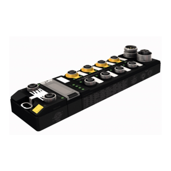
4.1 Device overview
Presents a visual and dimensional overview of the device.
4.2 Properties and features
Details the key characteristics and functionalities of the device.
4.3 Functions and operating modes
Explains the operational capabilities and modes of the device.
5 Installing
5.1 Installing the device in Zone 2 and Zone 22
Provides instructions for installing the device in hazardous Ex areas.
5.2 Mounting onto a mounting plate
Details the procedure for mounting the device onto a flat surface.
5.3 Grounding the device
Explains the grounding concepts for the device and its shielding.
6 Connecting
6.1 Connecting the device in Zone 2 and Zone 22
Provides safety instructions for connecting the device in Ex areas.
6.2 Connecting the M12 connectors
Details how to connect cables using M12 connectors with proper torque.
6.3 Connecting the device to Ethernet
Explains how to connect the device to an Ethernet network.
6.4 Connecting the power supply
Describes how to connect the device's power supply.
6.5 Connecting safe sensors and actuators
Details how to connect safe sensors and actuators to the device.
6.6 Switching examples
Provides examples of input and output switching configurations.
7 Commissioning
7.1 Initial commissioning
Covers the steps for initial setup and installation of the device.
7.2 Safety planning
Outlines the operator's responsibility for safety planning.
7.3 Addressing the device
Explains how to assign addresses to the device.
8 Configuring
8.1 Installing Turck Safety Configurator
Guides the user through the installation process of the configuration software.
8.2 Integrate Turck Safety Configurator in TIA Portal
Explains how to integrate the software into the TIA Portal environment.
8.3 Licensing Turck Safety Configurator
Describes the licensing process for the safety configuration software.
8.4 Creating a configuration with the TSC Commissioning wizard
Details how to create a device configuration using the wizard.
8.5 Loading the configuration with the TSC commissioning wizard
Guides on how to load the created configuration into the device.
8.6 Application example – configuring a safety function in TSC
Provides a practical example of configuring a safety function.
8.7 Configuring single channel safety sensors
Explains how to configure safety sensors that use a single channel.
8.8 Configuring the device at PROFINET/PROFIsafe in TIA Portal
Details device configuration within TIA Portal for PROFINET/PROFIsafe.
9 Operating
9.1 LED displays
Describes the meaning of the device's various LED indicators.
9.2 Status- and control word
Explains the structure and meaning of the status and control words.
9.3 Process input data
Details the structure of the process input data for the module.
9.4 Process output data
Details the structure of the process output data for the module.
9.5 Using the configuration memory
Explains how to use the memory stick for configuration storage and transfer.
10 Restarting after Device Exchange or Modification
10.1 Changing a device
Guides on replacing a device with a new one.
14 Technical Data
14.1 General technical data
Presents general specifications for devices, power supply, interfaces, and times.
16 Connecting
16.1 Connecting the device in Zone 2 and Zone 22
Provides safety instructions for connecting the device in Ex areas.
16.2 Connecting digital sensors and actuators
Explains how to connect standard digital sensors and actuators.
17 Configuring
17.1 Parameters
Lists configurable parameters with their default values and descriptions.
18 Operating
18.1 Process input data
Details the structure of the process input data for the module.
18.2 Process output data
Details the structure of the process output data for the module.
21 Connecting
21.1 Connecting the device in Zone 2 and Zone 22
Provides safety instructions for connecting the device in Ex areas.
21.2 Connecting IO-Link Devices
Explains how to connect IO-Link devices to the device's ports.
22 Commissioning
22.1 Commissioning an IO-Link device with IO-Link V1.0
Guides on commissioning IO-Link devices using V1.0 specification.
22.2 Commissioning an IO-Link device with IO-Link V1.1
Guides on commissioning IO-Link devices using V1.1 specification.
23 Configuring
23.1 Parameters
Lists configurable parameters for IO-Link channels.
24 Operating
24.1 LED displays – IO-Link channels
Explains the LED indicators for the device's IO-Link channels.
24.2 Process input data
Details the structure of the process input data for the module.
24.3 Process output data
Details the structure of the process output data for the module.
24.4 Software diagnostic messages
Lists and explains software diagnostic messages for DXP and IO-Link.
24.5 FSU - Fast Start-Up (prioritized startup)
States that Fast Start-Up is not supported by the device.
24.6 Specific configuration of the IO-Link ports via GSDML (SIDI)
Explains device integration using GSDML for IO-Link ports.
24.7 IO-Link functions for acyclic communication
Describes how to access IO-Link data using acyclic communication calls.
24.8 Using the data storage mode
Explains how to use the data storage mode for IO-Link devices.
25 Troubleshooting
25.1 Eliminating parameterization errors
Provides solutions for common parameterization errors in DXP and IO-Link channels.
Need help?
Do you have a question about the TBPN-LL-FDIO1-2IOL and is the answer not in the manual?
Questions and answers