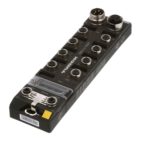
turck TBEN-L Series Operating Instructions Manual
Compact i/o modules for ethernet
Hide thumbs
Also See for TBEN-L Series:
- Instructions for use manual (64 pages) ,
- Instructions for use manual (126 pages)


Need help?
Do you have a question about the TBEN-L Series and is the answer not in the manual?
Questions and answers