
Subscribe to Our Youtube Channel
Related Manuals for turck TBEN-L PLC Series


Summary of Contents for turck TBEN-L PLC Series
- Page 1 Your Global Automation Partner TBEN-L…-PLC-… Compact CODESYS V3 PLC Operating instructions...
-
Page 3: Table Of Contents
Table of Contents About these Instructions Target Groups Explanation of Symbols Additional Documents Notes on the Product Product Identification 2.1.1 Scope of Delivery 2.1.2 Legal Requirements 2.1.3 Manufacturer and Service For Your Safety Intended Use General Safety Instructions Product description Device overview Block Diagram Technical data... - Page 4 General start-up 9.5.1 Installing the device package in CODESYS 9.5.2 Creating a standard project with TBEN-L-PLC-in CODESYS V3.5.8.10 Modbus TCP Master Hans Turck GmbH & Co. KG | T +49 208 4952-0 | F +49 208 4952-264 | more@turck.com | www.turck.com...
- Page 5 9.6.1 Configuring the Modbus TCP Master 9.6.2 Configuring the external Modbus TCP Slave Modbus TCP-Slave Device 9.7.1 Configuring Modbus TCP Slave Device Modbus RTU Master 9.8.1 Configuring the Modbus RTU Master Modbus RTU Device 9.9.1 Configuring the Modbus RTU Device 9.10 PROFINET Controller 9.10.1 Configuring the PROFINET Controller...
- Page 6 Slot Parameters 11.12.1 Parameterizing the in- and outputs 11.13 Using mobile devices 11.14 Web server logout 11.15 Web server deactivated Hans Turck GmbH & Co. KG | T +49 208 4952-0 | F +49 208 4952-264 | more@turck.com | www.turck.com...
-
Page 7: About These Instructions
About these Instructions These operating instructions describe the structure, functions and the use of the product and will help you to operate the product as intended. Read these instructions carefully before using the product. This is to avoid possible damage to persons, property or the device. Retain the instructions for future use during the service life of the product. -
Page 8: Additional Documents
Data sheet Quick Start Guide Product flyer CAD data CODESYS package GDSML- and EDS-files Hans Turck GmbH & Co. KG | T +49 208 4952-0 | F +49 208 4952-264 | more@turck.com | www.turck.com... -
Page 9: Notes On The Product
45472 Muelheim an der Ruhr Germany Turck supports you with your projects, from initial analysis to the commissioning of your applica- tion. The Turck product database contains software tools for programming, configuration or com- missioning, data sheets and CAD files in numerous export formats. You can access the product data- base at the following address: www.turck.de/products... - Page 10 Notes on the Product Hans Turck GmbH & Co. KG | T +49 208 4952-0 | F +49 208 4952-264 | more@turck.com | www.turck.com...
-
Page 11: For Your Safety
The product is designed according to state-of-the-art technology. However, residual risks still exist. Observe the following warnings and safety notices to prevent damage to persons and property. Turck accepts no liability for damage caused by failure to observe these warning and safety notices. Intended Use The devices are only intended for use in industrial applications. - Page 12 For Your Safety Hans Turck GmbH & Co. KG | T +49 208 4952-0 | F +49 208 4952-264 | more@turck.com | www.turck.com...
-
Page 13: Product Description
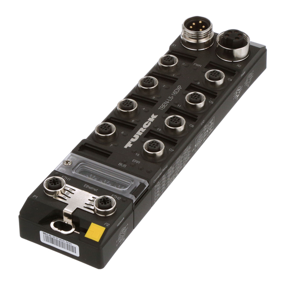
Product description The CODESYS V3 programmable TBEN-L-PLC- can be used as autonomous PLCs or as decentral PLCs in a network interconnection for a fast preprocessing of signals. The devices allow autono- mous control of applications without higher-level control. The Ethernet ports serve as interface for programming, configuration and Ethernet/ field bus com- munication. -
Page 14: Device Overview
Product description Device overview 38.8 30.2 60.4 230.5 Fig. 1: Dimensions Hans Turck GmbH & Co. KG | T +49 208 4952-0 | F +49 208 4952-264 | more@turck.com | www.turck.com... -
Page 15: Block Diagram
Block Diagram V1 + AUX1 – – – – RS485 = DATA B RS232 = RXD Supply RS485 = DATA A V1 + RS232 = TXD V2 + 3 V1 – LED0 RS485/ 5 FE RS232 LED1 µC V1 + AUX1 V1 Diag V2 Diag... -
Page 16: Technical Data
Ethernet, USB Cycle time < 1ms for 1000 IL- commands (without I/O cycle) Input data 8 kByte Output data 8 kByte Hans Turck GmbH & Co. KG | T +49 208 4952-0 | F +49 208 4952-264 | more@turck.com | www.turck.com... - Page 17 Serial interface Signal type RS232 or RS485 Number of channels Operation mode RS232 Signal low level -18 to -3 VDC Signal high level 3 to 18 VDC Transmission signals TxD, RxD Transmission rate 9600 to 230400 bps Transmission type Full duplex Cable length 15 m at 19200 baud (max.
- Page 18 512 TxPDOs Modbus TCP Master Max. number of devices Min. cycle time 2 ms Max. number of devices at 2 ms Hans Turck GmbH & Co. KG | T +49 208 4952-0 | F +49 208 4952-264 | more@turck.com | www.turck.com...
- Page 19 EtherNet/IP™ Scanner Input data max. 8 kByte Output data max. 8 kByte Max. number of devices at 10 ms PROFINET Controller Max. number of devices Min. cycle time 1 ms Max. number of devices at 1 ms Modbus RTU Master Max.
- Page 20 Product description Hans Turck GmbH & Co. KG | T +49 208 4952-0 | F +49 208 4952-264 | more@turck.com | www.turck.com...
-
Page 21: Mounting
Mounting The devices must be attached to a level, pre-drilled and grounded mounting surface. Attach the module to the mounting surface with two M6 screws. The maximum tightening torque for the screws is 1.5 Nm. M6 (2x) max. 1.5 Nm 218 [5.58] Fig. -
Page 22: Grounding The Device
(pin 5) for connecting the sensors and actuators. The grounding screw (3) connects the device with the system's reference potential. Hans Turck GmbH & Co. KG | T +49 208 4952-0 | F +49 208 4952-264 | more@turck.com | www.turck.com... -
Page 23: Grounding The Device (Fe)
5.1.2 Grounding the device (FE) The grounding clip and the metal ring are connected to each other. A mounting screw through the bottom mounting hole in the module connects the shielding of the fieldbus lines to the functional ground of the power supply and the connected devices and to the reference potential of the sys- tem. - Page 24 Mounting Hans Turck GmbH & Co. KG | T +49 208 4952-0 | F +49 208 4952-264 | more@turck.com | www.turck.com...
-
Page 25: Connecting
Connecting Connecting the Power Supply Connect the device to the power supply according to Fig. 8: Pin assignment TBEN-L4-PLC- Fig. 9: Pin assignment TBEN-L5-PLC-. 1 BK = GND V2 1 RD = 24 VDC V2 2 BU = GND V1 2 GN = 24 VDC V1 3 GNYE = FE 3 WH = GND V1... -
Page 26: Connecting Serial Devices (Com 0 And Com 1)
1 2 3 4 5 2 = D – 3 = D + 4 = n.c. 5 = GND Fig. 16: USB Device port Hans Turck GmbH & Co. KG | T +49 208 4952-0 | F +49 208 4952-264 | more@turck.com | www.turck.com... -
Page 27: Rndis Driver
6.6.1 RNDIS driver The corresponding RNDIS driver is installed automatically during the DTM installation in PACTware™. The USB device port is shown in the DTM as additional Ethernet port. NOTE Use the interface BL Service Ethernet in the DTM for the connection to the device. USB Host port The USB Host port is designed as USB2.0-A-socket and serves for connecting USB memory sticks for the restore and backup of CODESYS programs and for the actualization of the device firmware (see... - Page 28 Connecting Hans Turck GmbH & Co. KG | T +49 208 4952-0 | F +49 208 4952-264 | more@turck.com | www.turck.com...
-
Page 29: Setting And Parameterizing
Setting and Parameterizing Address and operation mode setting The device address and the operation mode are set using a combination of the 2 rotary coding switches and DIP switch no. 1 (Mode) at the device. x 10 Fig. 18: Rotary coding and DIP switches DIP switches Rotary cod- Mode... -
Page 30: Restore Ip
In "manual allocation", a client's IP address is assigned by the network administrator, and DHCP is used simply to convey the assigned address to the client. Hans Turck GmbH & Co. KG | T +49 208 4952-0 | F +49 208 4952-264 | more@turck.com | www.turck.com... -
Page 31: Address Setting Via Pgm Mode
Address and operation mode setting (page 27)). NOTE After changing of the address-mode, a voltage reset must be done. The PGM-mode allows access of the Turck DTMs to the module’s network settings (see also Address setting via DTM (page 33)). -
Page 32: F_Reset (Reset To Factory Setting)
"Reset to factory settings") does not delete the CODESYS program (see also Reset to factory settings (page 36)). Hans Turck GmbH & Co. KG | T +49 208 4952-0 | F +49 208 4952-264 | more@turck.com | www.turck.com... -
Page 33: Address Setting With Turck Service Tool
7.1.7 Address setting with Turck Service Tool The Turck Service Tool enables direct access to the Ethernet-network via Ethernet. The IP configuration, as well as the PROFINET device name of the Ethernet device can be changed application specifically. Search for devices Scan the network using the "Search"... - Page 34 PROFINET-Device (page 68)). The PROFINET device name is set via the "Change (F2) button. Fig. 22: Setting the PROFINET device name Hans Turck GmbH & Co. KG | T +49 208 4952-0 | F +49 208 4952-264 | more@turck.com | www.turck.com...
-
Page 35: Address Setting Via Dtm
7.1.8 Address setting via DTM In a respective frame application e.g. PACTware™, the Turck DTMs allow direct access to Ethernet. The IP address, as well as the subnet mask of the Ethernet device, can be changed according to the application by using the Busaddress Management function of the BL Service Ethernet interface (TCP/IP) in the DTM. - Page 36 The firewall may inhibit the access of PACTware™ (FDT/DTM) to the Ethernet interface. In this case, please adapt your firewall respectively. Hans Turck GmbH & Co. KG | T +49 208 4952-0 | F +49 208 4952-264 | more@turck.com | www.turck.com...
-
Page 37: Set Button
Fig. 25: Changing the IP address 7.1.9 SET button Pressing the SET button activates the write access of the device's USB Host port functions, see also chapter 10, USB-Host-Port-Funktionen (page 93). USB Host Fig. 26: SET button 2017/03... -
Page 38: Reset To Factory Settings
Step7 "Reset to factory settings") does not delete the CODESYS program. Turck Service Tool Fig. 27: Turck Service Tool, reset to factory settings Hans Turck GmbH & Co. KG | T +49 208 4952-0 | F +49 208 4952-264 | more@turck.com | www.turck.com... - Page 39 Web server The function is only available after a login. Fig. 28: Web server, reset to factory settings 2017/03...
-
Page 40: Parameterizing
10 Mbps, half duplex mode. 10 Mbps, full duplex 100 Mbps, half duplex 100 Mbps, full duplex Fig. 29: Device parameters in CODESYS Hans Turck GmbH & Co. KG | T +49 208 4952-0 | F +49 208 4952-264 | more@turck.com | www.turck.com... -
Page 41: Parameters Of The Local I/Os
7.2.2 Parameters of the local I/Os DXP channels Default parameters are displayed in bold. Parameter name Value Description Activate output The output is deactivated. The output is activated. Manual output reset after The output switches on automatically after an overcurrent overload. - Page 42 The 24 VDC sensor/actuator supply at Pin1 of the connector is switched off. Fig. 31: Parameters of the DXP channels in CODESYS Hans Turck GmbH & Co. KG | T +49 208 4952-0 | F +49 208 4952-264 | more@turck.com | www.turck.com...
-
Page 43: Real Time Clock (Rtc)
60 °C 168 hours up to 70 °C 36 hours The Real Time Clock can be set using by the Turck Service Tool, the device's web server or via COD- ESYS. 7.3.1 Setting the RTC with Turck Service Tool The turck Service Tool sets the RTC depending on the system time of the PC. -
Page 44: Setting The Rtc Via The Web Server
The web server allows the setting of the RTC directly or via SNTP server. Fig. 33: Setting the RTC via the web server Hans Turck GmbH & Co. KG | T +49 208 4952-0 | F +49 208 4952-264 | more@turck.com | www.turck.com... - Page 45 If the RTC is set via SNTP and the device has a connection to the SNTP server, than changes of the RTC via Turck Service Tool or the CODESYS library have no effect. Activate the SNTP server and enter the server address.
-
Page 46: Setting The Rtc Via Codesys
In CODESYS the RTC is set in the device for example using the CODESYS library "CAA Real time Clock Extern". Fig. 35: CAA Real time Clock Extern in CODESYS Hans Turck GmbH & Co. KG | T +49 208 4952-0 | F +49 208 4952-264 | more@turck.com | www.turck.com... -
Page 47: Operation
Operation LED displays Every device displays the following statuses via LEDs: PLC status (LED RUN), Application specific LED APPL (freely programmable via CODESYS) Supply voltage (LED PWR) Common error (LED ERR) Bus status (LED BUS) ... - Page 48 Output active with overload/short circuit blink- Short-circuit at the sensor/actuator supply for the respective connector. Both LEDs at the connector are blinking. Hans Turck GmbH & Co. KG | T +49 208 4952-0 | F +49 208 4952-264 | more@turck.com | www.turck.com...
-
Page 49: Diagnostics
Diagnostics Fig. 36: Diagnostics in CODESYS Diagnostics Description Overcurrent VAUX2 pin 1 Cx (Chy - z) Overcurrent VAUX2 at pin 1 of the channel Overcurrent output Chx Overcurrent at the respective output 2017/03... -
Page 50: Module Status
The Force Mode of the DTM is activated. The output states may not correspond to the settings send from the field bus or resulting from the CODESYS program. Hans Turck GmbH & Co. KG | T +49 208 4952-0 | F +49 208 4952-264 | more@turck.com | www.turck.com... -
Page 51: Sftp Access
SFTP access The SFTP access is done via a FTP client program (e.g. FileZilla): Server (SFTP protocol) IP address of the device User name sftpuser Password password Port NOTE The password for the SFTP access is synchronized to the password for the web server. Changing the password for the SFTP access also changes the web server password (see page 106). -
Page 52: Firmware Update
NOTE A firmware update is only possible if no program is active on the device. The firmware update can be done using a USB storage device at the USB Host port or via the Turck DTM. Stop the program which is running on the PLC. -
Page 53: Codesys Functions
CODESYS functions The CODESYS 3 programmable TBEN-L-PLC- can be used as follows: Protocol Master/Controller/ Slave/Device Scanner/Manager ✔ ✔ page 56 page 60 Modbus TCP ✔ ✔ page 62 page 60 Modbus RTU ✔ ✔ page 66 page 69 PROFINET ✔ ✔... -
Page 54: Possible Combinations Slave/Slave
CAA CiA 405, 3.5.8.0 Serial communication CAA SerialCom, 3.5.6.0 Time and date CAA DTUtil Extern, 3.5.5.0 CAA Real Time Clock Extern, 3.5.5.4 Hans Turck GmbH & Co. KG | T +49 208 4952-0 | F +49 208 4952-264 | more@turck.com | www.turck.com... -
Page 55: General Start-Up
General start-up 9.5.1 Installing the device package in CODESYS Download the CODESYS-Package "TBEN-Lx-PLC Vx.x.x.x.package" from www.turck.com. Install the package using the CODESYS Package Manager "Tools Package Manager". Fig. 40: Package Manager in CODESYS The device package for CODESYS contains all necessary files ... -
Page 56: Creating A Standard Project With Tben-L-Plc-In Codesys V3.5.8.10
Create a new standard project with TBEN-L-PLC- as CODESYS device. Fig. 41: Selecting the TBEN-L-PLC- as CODESYS device The CODESYS project is created. Fig. 42: CODESYS project Hans Turck GmbH & Co. KG | T +49 208 4952-0 | F +49 208 4952-264 | more@turck.com | www.turck.com... - Page 57 In addition to the PLC logic, the project contains: 5 LEDs for free use in the program – Each LED uses 2 bit in the process output data of the device. They are automatically mapped to the output bits %QX8000.0 to %QX8001.1 (see Fig.
-
Page 58: Modbus Tcp Master
Select "eth0" under "network interface". The IP address is set automatically. Fig. 43: Adding and configuring the Ethernet interface Hans Turck GmbH & Co. KG | T +49 208 4952-0 | F +49 208 4952-264 | more@turck.com | www.turck.com... - Page 59 Add Modbus TCP Master. Fig. 44: Add Modbus TCP Master 2017/03...
-
Page 60: Configuring The External Modbus Tcp Slave
In this example the Turck multiprotocol device TBEN-S1-4DIP-4DOP is used as Modbus Slave. Fig. 46: Configuring the external Modbus TCP Slave Add Modbus Slave channels for the communication with the slave. Hans Turck GmbH & Co. KG | T +49 208 4952-0 | F +49 208 4952-264 | more@turck.com | www.turck.com... - Page 61 Observe the process data offsets of the slave. In the example (Fig. 47: Adding Modbus Slave channels) the slave's process output data start with register 0x0800. Fig. 47: Adding Modbus Slave channels 2017/03...
-
Page 62: Modbus Tcp-Slave Device
Therefore define the number of in- and output registers (input and holding registers) which have to be exchanged with the higher-level Modbus TCP-master. Fig. 48: Configuring Modbus TCP Slave Device Hans Turck GmbH & Co. KG | T +49 208 4952-0 | F +49 208 4952-264 | more@turck.com | www.turck.com... - Page 63 Which data will be mapped into the input and holding registers, depends on assignments in the PLC program or in the I/O mapping of the TBEN-L-PLC-. Fig. 49: Modbus TCP Slave Device data mapping 2017/03...
-
Page 64: Modbus Rtu Master
Modbus commands instead of interrupting the Modbus communication.? Otherwise the error has to be reset using a slave function block. Fig. 50: Add Modbus RTU Master Hans Turck GmbH & Co. KG | T +49 208 4952-0 | F +49 208 4952-264 | more@turck.com | www.turck.com... - Page 65 Configuring the external Modbus RTU Slave Add an external Modbus RTU slave using the "Add Device" function and configure it. In this example the Turck multiprotocol device TBEN-S2-2COM-4DXP is used as Modbus Slave. Add Modbus Slave Channels for the communication with the Slave....
-
Page 66: Modbus Rtu Device
Therefore define the number of in- and output registers (input and holding registers) which have to be exchanged with the higher-level Modbus TCP-master. Fig. 52: Configuring the Modbus_Serial_Device Hans Turck GmbH & Co. KG | T +49 208 4952-0 | F +49 208 4952-264 | more@turck.com | www.turck.com... - Page 67 Which data will be mapped into the input and holding registers, depends on assignments in the PLC program or in the I/O mapping of the TBEN-L-PLC-. Fig. 53: Modbus_Serial_Device data mapping 2017/03...
-
Page 68: Profinet Controller
Select "eth0" under "network interface". The IP address is set automatically. Fig. 54: Adding and configuring the Ethernet interface Hans Turck GmbH & Co. KG | T +49 208 4952-0 | F +49 208 4952-264 | more@turck.com | www.turck.com... - Page 69 Add the PN Controller. Fig. 55: Adding the PN Controller NOTE The Device addresses under "Default Slave IP Parameter" and the Ethernet interface of the TBEN-L-PLC- have to be in the same subnet. 2017/03...
-
Page 70: Configuring An External Profinet Device
Fig. 56: Configuring an external PROFINET Device NOTE The IP addresses of the PROFINET Devices and the PN Controller have to be in the same subnet. Hans Turck GmbH & Co. KG | T +49 208 4952-0 | F +49 208 4952-264 | more@turck.com | www.turck.com... -
Page 71: Profinet Device
9.11 PROFINET Device Properties max. number of I/O data 1024 byte in total (512 IN + 512 OUT) 9.11.1 Configuring the PROFINET Device in CODESYS The Profinet_Device from 3S - Smart Software Solutions GmbH is used. Add the Profinet_Device to Ethernet using the "Add Device" function. ... - Page 72 Fig. 58: PROFINET-device data mapping NOTE The PROFINET-device shows an error as long as a connection to the PROFINET Controller is established. Hans Turck GmbH & Co. KG | T +49 208 4952-0 | F +49 208 4952-264 | more@turck.com | www.turck.com...
-
Page 73: Configure The Profinet Device In The Profinet Controller
The following example shows the PROFINET-device configuration in TIA-Portal V13 from Siemens. The PROFINET-CODESYS-device is configured as standard PROFINET Device in TIA-Portal. Installing the GSDML-file Install the device's GSDML-file (GSDML-V2.3-TURCK-CDS3_PN_Device--.xml) in the PROF- INET configuration software. It can be downloaded fromwww.turck.com ... - Page 74 Set all necessary IP-settings and assign a PROFINET-device name or use the device name which has already been assigned to the device. Fig. 60: Settings PROFINET-interface (CDS3 PN Device) Hans Turck GmbH & Co. KG | T +49 208 4952-0 | F +49 208 4952-264 | more@turck.com | www.turck.com...
- Page 75 Configuring the in- and output data Configure the in- and output data, which have to be exchanged with the CODESYS-device. NOTE The configuration of the data in TIA-Portal has to be done in reverse order compared to the configuration in CODESYS. Input data in TIA-Portal are output-data in CODESYS, and vice versa.
-
Page 76: Ethernet/Ip™ Scanner
Select "eth0" under "network interface". The IP address is set automatically. Fig. 62: Adding and configuring the Ethernet interface Hans Turck GmbH & Co. KG | T +49 208 4952-0 | F +49 208 4952-264 | more@turck.com | www.turck.com... - Page 77 Add the Ethernet/IP™ Scanner Fig. 63: Adding the Ethernet/IP™ Scanner 2017/03...
-
Page 78: Configuring An External Ethernet/Ip™ Device
In this example the Turck multiprotocol device TBEN-L5-8IOL is used as EtherNet/IP™ Device. Fig. 64: Configuring an external EtherNet/IP™ Device Hans Turck GmbH & Co. KG | T +49 208 4952-0 | F +49 208 4952-264 | more@turck.com | www.turck.com... -
Page 79: Ethernet/Ip™ Slave (Device)
9.13 EtherNet/IP™ Slave (Device) Properties max. number of I/O data 496 byte IN 492 byte OUT 9.13.1 Configuring the EtherNet/IP™ Device in CODESYS The "Ethernet IP Slave" from 3S - Smart Software Solutions GmbH is used. Add the EtherNet/IP™ Device to the Ethernet interface using the "Add Device" function. ... - Page 80 Which data will be mapped into the configured input and output data, depends on assignments in the PLC program or in the I/O mapping of the TBEN-L-PLC-. Fig. 66: EtherNet/IP™ Slave data mapping Hans Turck GmbH & Co. KG | T +49 208 4952-0 | F +49 208 4952-264 | more@turck.com | www.turck.com...
-
Page 81: Configuring The Ethernet/Ip™ Device In Ethernet/Ip™ Scanner
TBEN-L-PLC- Installing the EDS-file Install the device's EDS-file (Turck CDS3.eds) in the configuration software. It can be downloaded fromwww.turck.com The device is added as "CDS 3 Ethernet/IP Slave" to the device catalog in RSLogix. Fig. 67: "CDS 3 Ethernet/IP Slave" in the device catalog in RSLogix5000... - Page 82 Configuring the Device Enter the device name and the device's IP address. Fig. 68: Settings at the "CDS3 Ethernet/IP Slave" Hans Turck GmbH & Co. KG | T +49 208 4952-0 | F +49 208 4952-264 | more@turck.com | www.turck.com...
- Page 83 Configuring the in- and output data The device is automatically configured with a data width of 256 byte in- and 256 byte output data. Fig. 69: EtherNet/IP™-Connection "CDS3 Ethernet/IP Slave" NOTE The EDS file limits the maximum number of in- and output data for the device to 256 Byte each.
-
Page 84: Canopen Manager
The CANopen Manager from 3S - Smart Software Solutions GmbH is used. Add the CANopen Manager to the CANbus and configure it. Fig. 71: Adding the CANopen Manager Hans Turck GmbH & Co. KG | T +49 208 4952-0 | F +49 208 4952-264 | more@turck.com | www.turck.com... -
Page 85: Configuring An External Canopen Device
Configuring an external CANopen device Add an external CANopen device to the CANopen Manager using the "Add Device" function and configure it. In this example the Turck BL67-CANopen gateway BL67-GW-CO is used as CANopen device. Fig. 72: Configuring the CANopen Device 2017/03... -
Page 86: Canopen Device
Add in- and output areas for the device via the "Edit I/O Area" function. Fig. 73: Configuring the CANopen Device Hans Turck GmbH & Co. KG | T +49 208 4952-0 | F +49 208 4952-264 | more@turck.com | www.turck.com... - Page 87 Which data will be mapped into the configured input and output data, depends on assignments in the PLC program or in the I/O mapping of the TBEN-L-PLC-. Fig. 74: CANopen Device data mapping 2017/03...
-
Page 88: Export An Eds File For The Canopen Device
Use the "Export EDS File..." function to create and export a device specific EDS file for the use in a higher-level CANopen PLC. Fig. 75: Exporting the EDS-file Hans Turck GmbH & Co. KG | T +49 208 4952-0 | F +49 208 4952-264 | more@turck.com | www.turck.com... -
Page 89: Sae J1939 Manager
9.16 SAE J1939 Manager Properties Max. number of devices Input data max. 8 kByte Output data max. 8 kByte 9.16.1 Configuring the J1939 Manager The J1939 Manager from 3S - Smart Software Solutions GmbH is used. Add the J1939 Manager to the CANbus using the "Add Device" function and configure it. Fig. -
Page 90: Configuring An External Sae J1939-Device (Ecu)
Add the "J1939_ECU" from 3S - Smart Software Solutions GmbH to the J1939 Manager and con- figure it according to the manufacturer specifications for the connected J1939 device. Fig. 77: Configuring the J1939_ ECU Hans Turck GmbH & Co. KG | T +49 208 4952-0 | F +49 208 4952-264 | more@turck.com | www.turck.com... -
Page 91: Displaying Task And Processor Information
9.17 Displaying task and processor information 9.17.1 Displaying the Average Cycle Time The average cycle time for the task with the highest priority should not be higher than 80 % of the cycle time set for this task. In the following example the Profinet_IOTask has the highest priority, the cycle time is set to 1 ms: Fig. - Page 92 1 ms × 80 % = 800 μs An average cycle time of 800 μs should not be exceeded for this example. Hans Turck GmbH & Co. KG | T +49 208 4952-0 | F +49 208 4952-264 | more@turck.com | www.turck.com...
-
Page 93: Displaying Processor Information
9.17.2 Displaying processor information Information about the processor load can be displayed in the PLC Shell of the TBEN-L-PLC- using the function "plcload". Call the function "plcload" in the device's PLC Shell. Fig. 80: Call the function "plcload" The PLC load for the TBEN-L-PLC-s displayed in %. Fig. -
Page 94: Codesys-Exception "Processorloadwatchdog
Displaying the Average Cycle Time (page 89). Fig. 82: Exception in CODESYS in case of processor overload Hans Turck GmbH & Co. KG | T +49 208 4952-0 | F +49 208 4952-264 | more@turck.com | www.turck.com... -
Page 95: Usb Host Port Functions
10 USB Host port functions The USB Host port serves for connecting USB storage devices for the storage, restore and transfer of CODESYS applications as well as for updating the device firmware. NOTE The USB Host function can be deactivated using the web-server of the CODESYS program (see chapter 7.2,... -
Page 96: Functions Of The Usb Host Port
USB_DATA_WRITE: Loading of CODESYS recipes and/or log-files from the storage device into the device – FW_UPDATE: Firmware update of the device Hans Turck GmbH & Co. KG | T +49 208 4952-0 | F +49 208 4952-264 | more@turck.com | www.turck.com... -
Page 97: General Notes/Prerequisites
10.2.1 General notes/prerequisites The storage device is formatted in FAT (FAT or FAT32). The storage device does contain only one folder. If the storage device contains more than one folder, not function is executed. The RUN-LED displays errors, see Behavior of the RUN-LED in case of an error, page ... -
Page 98: Function Overview
All other applications on the device are deleted without further warnings. The device automatically executes a restart after unplugging the storage device. Hans Turck GmbH & Co. KG | T +49 208 4952-0 | F +49 208 4952-264 | more@turck.com | www.turck.com... - Page 99 Function Folder name Description CODESYS autom. program device restart Restore 2 RESTORE_2 Loading the CODESYS application and further device data from STOP the storage device into the device. The following files are loaded from the storage device: – All *.app and *.crc files. –...
-
Page 100: Executing The Functions
The RUN-LED flashes orange with 1 Hz. The firmware update is completed. Unplug the storage device. The device is automatically restarted. Hans Turck GmbH & Co. KG | T +49 208 4952-0 | F +49 208 4952-264 | more@turck.com | www.turck.com... -
Page 101: Behavior Of The Run-Led In Case Of An Error
USB_DATA_WRITE Plug the storage device into the device. The RUN-LED flashes green with 0.5 Hz. Press the SET-button within the next 30 seconds for at least 3 seconds. The RUN-LED flashes green with 2 Hz. The data are stored to the device. ... - Page 102 USB Host port functions Hans Turck GmbH & Co. KG | T +49 208 4952-0 | F +49 208 4952-264 | more@turck.com | www.turck.com...
-
Page 103: The Web Server
11.1 Safety in the web server In the web server, a default-password is assigned to the Turck devices for the administrator access. We strongly recommend to use an individual password, in order to avoid possible misuse by a third party! This should be done in the context of the network security concept for the complete facility in which the modules are placed. -
Page 104: Start Page Of The Web Server (Home)
I/Os, the diagnostic information and the data for the control of the sensor/actuator supply is possible without administrator login. Fig. 83: Start page of the web server (Home) Hans Turck GmbH & Co. KG | T +49 208 4952-0 | F +49 208 4952-264 | more@turck.com | www.turck.com... -
Page 105: Station Diagnostics
11.4 Station Diagnostics Diagnostic messages of the device are displayed on the "Station Diagnostics"-page. Fig. 84: Diagnostics in the web server 2017/03... -
Page 106: Event Log
The Event Log shows the login information as well as the diagnostic information for the device. Fig. 85: Event Log Hans Turck GmbH & Co. KG | T +49 208 4952-0 | F +49 208 4952-264 | more@turck.com | www.turck.com... -
Page 107: Ethernet Statistics
The "Ethernet summarized statistics" contain the statistics for both Ethernet ports. 11.7 Links This page contains a link to the product page on the Turck website, on which further information (data sheets, configuration files, CAD data, etc.) for the device can be found. 2017/03... -
Page 108: Login /Password
Executing the "Reset to Factory Defaults" (see also Reset to Factory Defaults, page 110) also resets the password to "password". Hans Turck GmbH & Co. KG | T +49 208 4952-0 | F +49 208 4952-264 | more@turck.com | www.turck.com... - Page 109 Fig. 88: Change Admin password Change password Change the password in the web server. Write the changes into the device via "Submit". Restart the device. The device has accepted the new settings, the settings have become active. NOTE "Reset"...
-
Page 110: Network Configuration
"Reset" only resets the changes done in the web server mask back to the original values. The function does not influence the device itself. Hans Turck GmbH & Co. KG | T +49 208 4952-0 | F +49 208 4952-264 | more@turck.com | www.turck.com... -
Page 111: Station Configuration
11.11 Station Configuration The "Station Configuration"-page serves for parameterizing the following device functions: Deactivating the USB Host port or the web server Assigning a PROFINET device name The function is only available after a login. 11.11.1 Configuring the Ethernet interface ... -
Page 112: Reset To Factory Defaults
"Reset" only resets the changes done in the web server mask back to the original values. The function does not influence the device itself. Hans Turck GmbH & Co. KG | T +49 208 4952-0 | F +49 208 4952-264 | more@turck.com | www.turck.com... -
Page 113: Slot Parameters
11.12 Slot Parameters 11.12.1 Parameterizing the in- and outputs The "Parameters"-page is used to parameterize the device's in- and outputs. NOTE Parameter changes via the web server are only valid until the CODESYS program is down- loaded to the device again, the device is started with an active Boot application or param- eters are changed in CODESYS by online change. -
Page 114: Using Mobile Devices
If the web server is deactivated using the web server itself, further access to it is only pos- sible after a device reset to factory settings (see page 30) or via CODESYS (see page 38). Hans Turck GmbH & Co. KG | T +49 208 4952-0 | F +49 208 4952-264 | more@turck.com | www.turck.com... - Page 115 28 subsidiaries and over 60 representations worldwide! D301431 2017/03 *D301431ßß1703* www.turck.com...
Need help?
Do you have a question about the TBEN-L PLC Series and is the answer not in the manual?
Questions and answers