
Related Manuals for turck TBIP-L...-FDIO1-2IOL Series TBIP-L4-FDIO1-2IOL


Summary of Contents for turck TBIP-L...-FDIO1-2IOL Series TBIP-L4-FDIO1-2IOL
- Page 1 Your Global Automation Partner TBIP-L…-FDIO1-2IOL Safety Block I/O Module Instructions for Use...
- Page 2 Hans Turck GmbH & Co. KG | T +49 208 4952-0 | F +49 208 4952-264 | more@turck.com | www.turck.com...
-
Page 3: Table Of Contents
Part 1 – TBIP-L…-FDIO1-2IOL– Safe I/O channels Table of Contents About this user manual Documentation concept Target Groups of these Operating Instructions Additional Documents Manufacturer and Service For Your Safety Intended Use Foreseeable Misuse General Safety Instructions Residual Risks (EN ISO/ISO 12100-1) Proper and Safe Operation Warranty and Liability Legal Requirements... - Page 4 Starting the Software 8.0.5 Setting up a New Configuration 8.0.6 Adapting the Monitor Settings 8.0.7 Setting up a Standard Configuration Hans Turck GmbH & Co. KG | T +49 208 4952-0 | F +49 208 4952-264 | more@turck.com | www.turck.com...
- Page 5 8.0.8 Checking the Configuration 8.0.9 Loading the Configuration into the Safety Module. 8.0.10 Customizing the Configuration 8.0.11 Application Example 8.0.12 Basic Information 8.0.13 Used Hardware 8.0.14 Used Software 8.0.15 RSLinx – Searching the Network for Devices 8.0.16 Creating a New Project 8.0.17 Configuring the Project in RSLogix Designer Operating LED Displays...
- Page 6 Process Data of the Universal Standard I/O Channels 14.4.1 Process image TBPN-L1-FDIO1-2IOL 14.5 Parameters 14.6 Diagnostics/status 14.6.1 LED displays 14.6.2 Diagnostic messages Hans Turck GmbH & Co. KG | T +49 208 4952-0 | F +49 208 4952-264 | more@turck.com | www.turck.com...
- Page 7 Adapting the Process Data Mapping 16.8 Diagnostics and Status 16.8.1 LED Displays Channel LEDs (C4 to C5) 16.8.2 Diagnostic Data 16.9 Using IO-Link and Turck Device DTMs 16.9.1 Topology Scan IO-Link – Data Storage 17.1 Parameter "Data Storage Mode" = activated 17.2 Parameter "Data Storage Mode"...
- Page 8 Appendix 19.1 Start-up: IO-Link-Device with IO-Link V1.0 19.2 Start-up: IO-Link-Device with IO-Link V1.1 19.3 Start-up Problems – Frequently Failure Causes Hans Turck GmbH & Co. KG | T +49 208 4952-0 | F +49 208 4952-264 | more@turck.com | www.turck.com...
- Page 9 Part 1 – TBIP-L…-FDIO1-2IOL– Safe I/O channels Table of Contents About this user manual Documentation concept Target Groups of these Operating Instructions Additional Documents Manufacturer and Service For Your Safety Intended Use Foreseeable Misuse General Safety Instructions Residual Risks (EN ISO/ISO 12100-1) Proper and Safe Operation Warranty and Liability Legal Requirements...
- Page 10 Mode: DHCP (400) 6.4.3 Mode: PGM (500) 6.4.4 Mode: PGM-DHCP (600) 6.4.5 Resetting the IP Address (Safety Side), Switch Position "000" Hans Turck GmbH & Co. KG | T +49 208 4952-0 | F +49 208 4952-264 | more@turck.com | www.turck.com...
- Page 11 7.1.2 Setting the IP Address 7.1.3 Configuring in Turck Safety Configurator 7.1.4 Operation of the Device at the PLC Configuring with Turck Safety Configurator and Rockwell Studio 5000 8.0.1 Downloading the Software 8.0.2 Installing the Software 8.0.3 Licensing the Software 8.0.4...
- Page 12 10.1.4 Putting the Exchange Device into Operation Maintenance, repair, decommissioning and disposal 11.1 Maintenance 11.2 Repair 11.3 Decommissioning 11.4 Disposal Glossary of terms Hans Turck GmbH & Co. KG | T +49 208 4952-0 | F +49 208 4952-264 | more@turck.com | www.turck.com...
-
Page 13: Part 1: Tbip-L
About this user manual These operating instructions contain rules for the use of the devices in Safety Instrumented Systems (SIS). The assessment of the safety related values is based on IEC 61508, ISO 13849-1 and IEC 62061. The module serves for controlling signal devices as for example emergency stop buttons, position switches or OSSDs which are used to ensure human, material or machine protection. -
Page 14: Additional Documents
This symbol identifies steps that the user has to perform. RESULTS OF ACTION This symbol identifies relevant results of steps. Hans Turck GmbH & Co. KG | T +49 208 4952-0 | F +49 208 4952-264 | more@turck.com | www.turck.com... -
Page 15: Manufacturer And Service
45472 Muelheim an der Ruhr Germany Turck supports you with your projects, from initial analysis to the commissioning of your applica- tion. The Turck product database contains software tools for programming, configuration or com- missioning, data sheets and CAD files in numerous export formats. You can access the product data- base at the following address:www.turck.en/products... - Page 16 About this user manual Hans Turck GmbH & Co. KG | T +49 208 4952-0 | F +49 208 4952-264 | more@turck.com | www.turck.com...
-
Page 17: For Your Safety
The product is designed according to state-of-the-art technology. However, residual risks still exist. Observe the following warnings and safety notices to prevent damage to persons and property. Turck accepts no liability for damage caused by failure to observe these warning and safety notices. Intended Use The safe hybrid safety module TBIP-L…-FDIO1-2IOL is a filed bus device for an EtherNet/IP™... -
Page 18: Residual Risks (En Iso/Iso 12100-1)
non-observance of the user manual mounting, installation, configuration or commissioning by unqualified persons. Hans Turck GmbH & Co. KG | T +49 208 4952-0 | F +49 208 4952-264 | more@turck.com | www.turck.com... -
Page 19: Legal Requirements
Legal Requirements Manufacturers and operators of machines and plants in which the module TBIP-L…-FDIO1-2IOL is used are responsible for observing all relevant directives and standards. 2.7.1 National and International Directives and Standards Machine directive 2006/42/EG EMC directive 2004/108/EG ... - Page 20 For Your Safety Hans Turck GmbH & Co. KG | T +49 208 4952-0 | F +49 208 4952-264 | more@turck.com | www.turck.com...
-
Page 21: Product Description
The module provides four universal digital in-/outputs for the connection of unsafe signals which can switch up to 2A. In addition to that the module has two IO-Link-Master. In combination with Turck I/O hubs, up to 32 I/Os can be connected. -
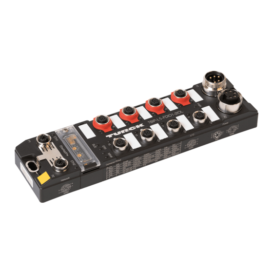
Page 22: Device Structure
Rotary coding switch for address setting (last byte of the IP address for the safe function unit) Ethernet 1 Ethernet 2 Functional earth Hans Turck GmbH & Co. KG | T +49 208 4952-0 | F +49 208 4952-264 | more@turck.com | www.turck.com... -
Page 23: Block Diagram
Block diagram DXP8 FDI0/1 FSO0 (intern) DXP9 DXP10 FDI2/3 DXP11 IO-Link Port1 DI12 (C/Q) FDX4/5 DXP13 IO-Link Port2 DI14 (C/Q) FDX6/7 FSO1 DXP15 (intern) Fig. 3: Block diagram 2018/02... -
Page 24: Technical Data
The last byte of the IP address for the safety side can be set using the rotary coding switches at the device page 41). QuickConnect not supported Hans Turck GmbH & Co. KG | T +49 208 4952-0 | F +49 208 4952-264 | more@turck.com | www.turck.com... - Page 25 Max. cable lengths Ethernet 100 m (per segment) Sensor/actuator 30 m Housing Material Fibre-glass reinforced Polyamide (PA6-GF30) Size 60.4 × 230.4 × 24 mm (w × l ×h) Window material Lexan Screw material 303 Stainless Steel Halogen-free Mounting Mounting 2 mounting holes, ? 6.3 mm Mounting distance ...
-
Page 26: Technical Data - Safety Inputs
7.5 ms at 0.2 ms test pulse width Times Internal delay time 10 ms (for calculating the Watchdog time) Reaction times Safety Characteristic Data (page 16) Hans Turck GmbH & Co. KG | T +49 208 4952-0 | F +49 208 4952-264 | more@turck.com | www.turck.com... -
Page 27: Technical Data - Safety Outputs
3.4.4 Technical data – safety outputs Safety outputs Suitable for inputs according to EN 61131-2, type 1 Output level in OFF-state Voltage level < 5V Current level < 1 mA Test pulses ohmic load, maximum 0.5 ms maximum 1.25 ms Interval between two test pulses typical 500 ms... -
Page 28: Safe I/O Channels
Incorrect wiring at the output (e.g. capacitive load, energetic recovery) Incorrect power supply Strong EMC disturbances Internal device error Hans Turck GmbH & Co. KG | T +49 208 4952-0 | F +49 208 4952-264 | more@turck.com | www.turck.com... -
Page 29: Safety Inputs (Fdi)
3.5.3 Safety inputs (FDI) Safe inputs for safety-related sensors Max. 4 × 2-channel safety switches and sensors Contact based switches, e.g. emergency switches, protective door switches Sensors with OSSD switch outputs with test pulses Sensors with OSSD switch outputs without test pulses Error detection/diagnostics: Internal: ... -
Page 30: Safety Outputs (Fdo)
Safe output, the load is connected between P-terminal and M-terminal (mass), necessary for spe- cial loads which need a separation from Ground. Hans Turck GmbH & Co. KG | T +49 208 4952-0 | F +49 208 4952-264 | more@turck.com | www.turck.com... -
Page 31: Universal Standard I/Os
A pluggable memory stick is included in the scope of delivery of TBPN-L1-FDIO1-2IOL. It serves for storing the safety function configured via Turck Safety Configurator. It allows to transfer the configuration of one device to another device (device exchange). the safety function is configured via Turck Safety Configurator (see chapter Configuring with Turck Safety Configurator and Rockwell Studio 5000). -
Page 32: Loading A Configuration From The Memory Chip
The device as well as the plugged memory chip are reset, the configuration is deleted. The procedure completed as soon as the ERR LED stops blinking. Hans Turck GmbH & Co. KG | T +49 208 4952-0 | F +49 208 4952-264 | more@turck.com | www.turck.com... -
Page 33: Deleting The Memory Chip
The procedure completed as soon as the ERR LED stops blinking. Deleting the Configuration via Turck Safety Configurator Select the function "Monitor operations Clear configuration" in the Turck Safety Configurator, Fig. 5: Deleting the configuration via Turck Safety Configurator ... -
Page 34: Module Behavior And Configuration Transfer
Device running during Check of the new con- operation figuration Configuration Device memory chip Hans Turck GmbH & Co. KG | T +49 208 4952-0 | F +49 208 4952-264 | more@turck.com | www.turck.com... -
Page 35: Mounting
Mounting Mount the device on a pre-drilled and grounded mounting surface. The mounting screw connects the functional earth with FE, if the mounting surface is grounded. ACHTUNG! Mechanical stress in the device Danger of material damage Mount the device onto an even mounting surface Mounting Material ... -
Page 36: Grounding The Device
By mounting the module onto a mounting plate through the mounting hole, the mounting screw is used to realize the connection to the reference potential of the installation. Hans Turck GmbH & Co. KG | T +49 208 4952-0 | F +49 208 4952-264 | more@turck.com | www.turck.com... -
Page 37: Grounding The Device (Fe)
4.3.1 Grounding the Device (FE) Grounding clamp and grounding ring are connected. The mounting screw (3) through the station's mounting hole connects the shield of the fieldbus lines to the FE of power supply and sensors/actuators and the installation's reference potential. If a common reference potential is not desirable, remove the metal clamp for decoupling and/or mounting the station by using a plastic screw. - Page 38 Mounting Hans Turck GmbH & Co. KG | T +49 208 4952-0 | F +49 208 4952-264 | more@turck.com | www.turck.com...
-
Page 39: Connecting
Seal unused 7/8'' connectors with protection caps which guarantee the protection class. under "Products Fieldbus technology Suitable protection caps can be found on www.turck.de Accessories". Protection of M12 Connectors (Ethernet and Sensors/Actuators) Protection caps for the M12 connectors are part of the device's scope of delivery but can also be ordered separately: under "Products ... -
Page 40: Connecting The Devices To Ethernet
We recommend pre-assembled 4-pole Ethernet cables according to under "Products Fieldbus ISO/IEC 11 801, CAT 5E. Suitable cables can be found on www.turck.de technology Accessories". Hans Turck GmbH & Co. KG | T +49 208 4952-0 | F +49 208 4952-264 | more@turck.com | www.turck.com... -
Page 41: Connecting The Power Supply
V2 = supply voltage 2 (not used in the device, only looped through) We recommend the use of pre-assembled 5-pole power supply cables, Turck type 52 (z.B. RKM52-1-RSM52). Suitable cables can be found on www.turck.de under "Prod- ucts Fieldbus technology Accessories". -
Page 42: Supply (Pelv)
Potential differences Dangerous additions of voltages Avoid potential differences between internal and external load voltage supplies (24 V DC). Hans Turck GmbH & Co. KG | T +49 208 4952-0 | F +49 208 4952-264 | more@turck.com | www.turck.com... -
Page 43: Connecting Sensors And Actuators
Class B supply (internal safe shutdown possible) Block diagram (page 15) DI/DO digital in-/output GND (V1) Ground V1 IO-Link GND (V1) Functional earth We recommend pre-assembled 5-pole sensor cables. Suitable cables can be found on under "Products Fieldbus technology Accessories". www.turck.de 2018/02... -
Page 44: Switching Examples
(pin 2). 2 FDO – 3 n.c. 4 FDO + 5 n.c. Fig. 13: Switching examples for safe outputs Hans Turck GmbH & Co. KG | T +49 208 4952-0 | F +49 208 4952-264 | more@turck.com | www.turck.com... -
Page 45: Setting Ip Addresses
Setting IP Addresses The TBIP-Lx-FDIO1-2IOL has two IP addresses. The first IP address addresses the safety side (left side) of the device. The second IP address addresses the non-safety (right side) of the device. Both IP addresses have to be addresses of the same network. The first 3 bytes of the IP address for the safety side (Main IP Address) can be adapted to the network environment via the device's web server. -
Page 46: Address Setting Via Rotary Coding Switches
Set the address switches to 901 and carry out a voltage reset at the device. The content of the memory chip is deleted. Hans Turck GmbH & Co. KG | T +49 208 4952-0 | F +49 208 4952-264 | more@turck.com | www.turck.com... -
Page 47: State Of Delivery
State of Delivery In the delivery state, the rotary switches are set to 600 PGM-DHCP ( s. page 42) In the delivery state, the device responds to the IP address of the safety side (Main IP Address): 192.168.1.254 If the PC used for the configuration is part of the same IP network, the page http://192.168.1.254/info.html can be opened in order to initially change some settings. -
Page 48: Setting The Ip Address Via The Web Server
After the changes, the web can be reached via the IP address of the safety side "Main IP Address". Hans Turck GmbH & Co. KG | T +49 208 4952-0 | F +49 208 4952-264 | more@turck.com | www.turck.com... -
Page 49: Setting The Ip Address For The Safety Side (Last Byte)
6.3.1 Setting the IP Address for the Safety Side (last Byte) The last byte of the IP address for the device's safety side is set via the 3 rotary coding switches under the device's protective cover. Open the cover over the rotary coding switches by using a screw driver. ... -
Page 50: Mode
Setting "000" is no operation mode! After having reset the IP address to the default values, the device has to be set to another mode. Hans Turck GmbH & Co. KG | T +49 208 4952-0 | F +49 208 4952-264 | more@turck.com | www.turck.com... -
Page 51: Commissioning
Commissioning Initial Commissioning 7.1.1 Mounting and Electrical Installation Please assure the proper closing of the protective cover over the rotary coding switches, see chapter 6, Setting IP Addresses. Mount TBIP-Lx-FDIO1-2IOL according to the instructions in chapter 4, Mounting. ... -
Page 52: Configuring In Turck Safety Configurator
Configuring with Turck Safety Configurator and Rockwell Studio 5000 (page 45)) and if all safety functions react as experted. Hans Turck GmbH & Co. KG | T +49 208 4952-0 | F +49 208 4952-264 | more@turck.com | www.turck.com... -
Page 53: Configuring With Turck Safety Configurator And Rockwell Studio 5000
If the coupon code is missing, please order a coupon code via E-mail under the following E-mail address: TM-BWSoftwareSupport@turck.com 8.1.4 Starting the Software Start the software via the program icon on the desktop. The TURCK Safety Configurator starts with the Start Assistant, which will lead through the first steps after program start. 2018/02... -
Page 54: Setting Up A New Configuration
Enter the configuration title in the register tab "Monitor information". Select the device type of the safety module (monitor type) in the section "Function range". Hans Turck GmbH & Co. KG | T +49 208 4952-0 | F +49 208 4952-264 | more@turck.com | www.turck.com... - Page 55 If no monitor is detected, open the settings for the interface to the connected device via the "Interface..."-button and enter the IP address of the connected device under "UDP". Fig. 18: Interface configuration If the IP-address of the device is not known, search the network via the "..."-button. ...
- Page 56 Configuring with Turck Safety Configurator and Rockwell Studio 5000 The safety module (monitor type) is detected, the connection is established. Fig. 20: Device (monitor type) detected Hans Turck GmbH & Co. KG | T +49 208 4952-0 | F +49 208 4952-264 | more@turck.com | www.turck.com...
-
Page 57: Setting Up A Standard Configuration
8.1.7 Setting up a Standard Configuration The register tab "Local I/O" in "Monitor settings" show the standard configuration for the local device in- and outputs. Fig. 21: Standard configuration of the local I/O Close the dialog box "Monitor settings" by pressing "OK". ... - Page 58 (FDI0/1 an FDI2/3). The inputs are also automatically assigned to the first two CIP Safety output bits. Fig. 22: Release circuits (OSSDs) of the standard configuration Hans Turck GmbH & Co. KG | T +49 208 4952-0 | F +49 208 4952-264 | more@turck.com | www.turck.com...
-
Page 59: Checking The Configuration
8.1.8 Checking the Configuration The Turck Safety Configurator checks the created configuration for logical errors, which meas, the logical wiring of the single components in the release circuits is checked. The configuration check does not consider double allocation etc. Start the check using the "Check configuration" -button. - Page 60 Signature with ID and time stamp which have to be entered in the EtherNet/IP™ PLC software, s. Assigning the Configuration Signature (page 75). Hans Turck GmbH & Co. KG | T +49 208 4952-0 | F +49 208 4952-264 | more@turck.com | www.turck.com...
- Page 61 Fig. 27: CIP Safety Configuration Signature Loading the Diagnostics Configuration If the diagnostics are activated, the TSC shows the state of the safety I/Os. Fig. 28: Released configuration, diagnostics configuration loaded 2018/02...
-
Page 62: Customizing The Configuration
2- channel safety related SIL3-inputs can be connected to the device. Possible input configurations: IP Address Fig. 29: Input configurations Hans Turck GmbH & Co. KG | T +49 208 4952-0 | F +49 208 4952-264 | more@turck.com | www.turck.com... - Page 63 IP Address Fig. 30: Output configurations Setting-up an Own configuration Adapt the standard configuration of the safety channels in the Turck Safety Configurator under "Monitor settings Local I/O". Fig. 31: Customized configuration of the local I/O Close the dialog box with "OK".
- Page 64 3. OSSD (no longer necessary, will be deleted, FDX4/5 Deleting OSSDs (page 57) 2. OSSD FSO0 1. OSSD FSO1 Hans Turck GmbH & Co. KG | T +49 208 4952-0 | F +49 208 4952-264 | more@turck.com | www.turck.com...
- Page 65 Deleting OSSDs OSSDs which are no longer necessary can be deleted in the component manager in the software. Open the component manger via "Display Window Component manager" Fig. 32: Open the component manager Delete the release circuits (OSSDs) which are no longer used in the component manager (in this example OSSD 3).
-
Page 66: Application Example
F-CPU. Release of the complete safety function via a release bit in the F-CPU (3. OSSD), s. page 66 Hans Turck GmbH & Co. KG | T +49 208 4952-0 | F +49 208 4952-264 | more@turck.com | www.turck.com... - Page 67 Add emergency shutdown in 64. OSSD The release circuit remains unchanged as it corresponds to the standard configuration. Emergency shutdown at SIL3-input FDI0/1, assigned to CIP Safety bit 1-7. Fig. 34: 64. OSSD with emergency shutdown Light grid (AOPD) in 63. OSSD ...
- Page 68 Fig. 36: Light grid (AOPD) in 63. OSSD The light grid at FDI2/3 is configured and assigned to CIP Safety output bit 1-6. Hans Turck GmbH & Co. KG | T +49 208 4952-0 | F +49 208 4952-264 | more@turck.com | www.turck.com...
- Page 69 Switch-on Unsafe Channels Permanently (1. and 2. OSSD) The unsafe channels at C4 - C7 of the device can be safe switched off via the internal safety outputs FSO0 and FSO1. If they have to be switched on permanently, then FSO0 and FSO1 need a permanent switch-on condition (TRUE).
- Page 70 Select the block "State of output switching element" from the Device library and place it at the function input. Hans Turck GmbH & Co. KG | T +49 208 4952-0 | F +49 208 4952-264 | more@turck.com | www.turck.com...
- Page 71 In the dialog box "State of output switching element x" select OSSD 63. Fig. 38: State of output switching element OSSD 63 2018/02...
- Page 72 The activation of the emergency shutdown at FDI0/1 or the light grid at FDI2/3 switches off out- put FDX4/5. Hans Turck GmbH & Co. KG | T +49 208 4952-0 | F +49 208 4952-264 | more@turck.com | www.turck.com...
- Page 73 Switch-off FDX6/7 at C3 (4. OSSD), if output FDX4/5 is switched. Output FDX6/7 has to switch off if output FDX4/5 (3. OSSD) switches off. Delete "CIP Safety input" in OSSD 4. Select the block "State of output switching element" from the Device library and place it at the function input.
- Page 74 After an error, the safety function will only restart if the emergency shutdown as well as the light grid are error free and the release bit in the F-CPU is set. Hans Turck GmbH & Co. KG | T +49 208 4952-0 | F +49 208 4952-264 | more@turck.com | www.turck.com...
-
Page 75: Basic Information
Configuring the device at CIP Safety (Rockwell Studio 5000) 8.2.1 Basic Information The TBIP-Lx-FDIO1-2IOL has two IP addresses. One IP address (in the example: 192.168.1.110) addresses the safety side (left side) of the device, the second IP address (in the example: 192.168.1.111) addresses the non-safety (right side) of the device. -
Page 76: Creating A New Project
If necessary, adjust the settings in the "New Project" window and complete the project creation using the "Finish” button. Fig. 44: Completing the project creation Hans Turck GmbH & Co. KG | T +49 208 4952-0 | F +49 208 4952-264 | more@turck.com | www.turck.com... - Page 77 the project is created and opened in the RSLogix Designer. Fig. 45: New project in the RSLogix Designer 2018/02...
-
Page 78: Configuring The Project In Rslogix Designer
Click "Set Project Path" to define he project path for the project. Fig. 47: Setting the project path Close the "Who Active" window. Hans Turck GmbH & Co. KG | T +49 208 4952-0 | F +49 208 4952-264 | more@turck.com | www.turck.com... - Page 79 Adding the Safety Side Right-click onto "Ethernet" "New Module". Fig. 48: Adding the device to the Ethernet via "New Module" 2018/02...
- Page 80 Fig. 50: New Module – Setting name and IP address Click "Change…" and set the "Communication Parameters" for the device. Hans Turck GmbH & Co. KG | T +49 208 4952-0 | F +49 208 4952-264 | more@turck.com | www.turck.com...
- Page 81 Enter the following values in the "module" tab: Module definition Vendor Product Type Product Code 14056 Major Revision Minor Revision Electronic Keying Compatible Module Fig. 51: Module Definition – Module 2018/02...
- Page 82 Click "OK" in the "New Module" window. Click "OK" to confirm the following note. Fig. 54: Note – Configuration Signature Hans Turck GmbH & Co. KG | T +49 208 4952-0 | F +49 208 4952-264 | more@turck.com | www.turck.com...
- Page 83 The Configuration Signature serves is used by the Controller to clearly identify the safety device and assures that the configured device matches the connected device concerning the configured safety function. The Configuration Signature is generated by the Turck Safety Configurator and is part of the configuration log in the Turck Safety Configurator ( s.
- Page 84 Fig. 57: Error at the TBIP-Lx-FDIOP1-2IOL Open the Module Properties by double-clicking the device entry in the project tree. Hans Turck GmbH & Co. KG | T +49 208 4952-0 | F +49 208 4952-264 | more@turck.com | www.turck.com...
- Page 85 The fault is specified under "Module Fault" in the "Connection" tab: "Safety Network Number Mismatch". Assigning the Safety Network Number The Safety Network Number clearly assigns the safety I/O module to one CIP Safety Controller. In case of several controllers in one network, this inhibits an unintentional access of another control- ler to the safety device.
- Page 86 Use the "Paste" button paste the controller's Safety Network Number into the module configu- ration and close the window with "OK". Fig. 59: Copying the Safety Network Number to the module properties Hans Turck GmbH & Co. KG | T +49 208 4952-0 | F +49 208 4952-264 | more@turck.com | www.turck.com...
- Page 87 Reset Ownership Go online. Click "Reset Ownership" in the "Safety" tab in the "Module Properties" and confirm all upcoming warnings with "Yes". Fig. 60: Reset Ownership Open again the "Safety Network Number" window in the "General" tab. ...
- Page 88 The Safety Network Number now clearly assigns the device to the CIP Safety Controller and the device is running. Fig. 62: Logix Designer – device running Hans Turck GmbH & Co. KG | T +49 208 4952-0 | F +49 208 4952-264 | more@turck.com | www.turck.com...
- Page 89 Reading Process Data Open the "Controller Tags" in the project tree by double-clicking the entry. Fig. 63: "Controller Tags" in the project tree The access to the input data (TBIP:I) and output data (TBIP:O) is possible. 2018/02...
- Page 90 Go offline. Right-click onto "Ethernet" "New Module". Fig. 64: Adding the device to the Ethernet via "New Module" Hans Turck GmbH & Co. KG | T +49 208 4952-0 | F +49 208 4952-264 | more@turck.com | www.turck.com...
- Page 91 Select the entry "Generic EtherNet/IP Module" in the "Select Module Type" window. Fig. 65: Generic EtherNet/IP Module Click "Create" to create the new device. The window "New Module" is opened. Assign a name to the new device in the "New Module" window, set the IP address (in the exam- ple 192.168.1.111) and enter the following values for the data format (Comm format"...
- Page 92 Go online and download the project to the controller by pressing the "Download" button. Confirm the download warning by pressing "Download" and switch back the controller to "remote Run" by pressing "OK". Hans Turck GmbH & Co. KG | T +49 208 4952-0 | F +49 208 4952-264 | more@turck.com | www.turck.com...
-
Page 93: Operating
Check the configuration in the configuration During operation: – software, execute a "Reset Ownership" if nec- Configuration faulty essary ( s. page 79). – Safety program missing: Configuration with the Turck Safety Configurator necessary. 2018/02... - Page 94 V1 and V2 OK No valid state, device switches to the safe state No valid state, device switches to the safe state Hans Turck GmbH & Co. KG | T +49 208 4952-0 | F +49 208 4952-264 | more@turck.com | www.turck.com...
-
Page 95: Error Led (Err)
9.1.3 Error LED (ERR) Meaning Remedy GREEN Device not supplied, Check the voltage supply. device switches to the safe state No diagnostic message available Diagnostic message pending Check the diagnostic message. No valid state, device switches to the safe state Initialization, configuration trans- Wait until the procedure is finished. - Page 96 No IO-Link communication and/or module error, invalid pro- cess data Channel in DI-mode Input active Input active Hans Turck GmbH & Co. KG | T +49 208 4952-0 | F +49 208 4952-264 | more@turck.com | www.turck.com...
-
Page 97: Status And Control Word
Status and Control Word 9.2.1 Status Word The status word is mapped to the beginning of the process data. Bit Bit Bit Bit Bit Bit Bit Bit Bit Bit Bit Bit ... -
Page 98: Module Status
The Force Mode is activated, which means, the actual output values may no match the ones defined and sent by the field bus. Hans Turck GmbH & Co. KG | T +49 208 4952-0 | F +49 208 4952-264 | more@turck.com | www.turck.com... -
Page 99: Process Input Data
Process Input Data 9.3.1 Overview - Complete Module The process input data of TBIP-L…-FDIO1-2IOL are structured as follows: Word Status Status and Control Word (page 89) word Status: Basic n + 1 … n + 2 Standard I/O channels and IO-Link master channels Fieldbus n + 3 bits... -
Page 100: Process Input Data - Safe I/O Channels
TEST WAI Connector C7 Connector C6 OVL - TC TC ERR TEST WAI RGG OVL - TC TC ERR TEST WAI Hans Turck GmbH & Co. KG | T +49 208 4952-0 | F +49 208 4952-264 | more@turck.com | www.turck.com... - Page 101 FBI 0-4 to FBI 1-7 Inputs in TBIP-L…-FDIO1-2IOL which can be addressed by the unsafe part of the safety controller. These bits have to be configured by the user in Turck Safety Configurator. Fig. 68: Input assignment in Turck Safety Configurator 2018/02...
- Page 102 Name Code Meaning No Memory Chip Plugged NCNF No Configuration Available CNFMV Configuration Mismatch COMLO Communication loss FERR Fatal Error Hans Turck GmbH & Co. KG | T +49 208 4952-0 | F +49 208 4952-264 | more@turck.com | www.turck.com...
- Page 103 Safe Status (connector C0 - C7) Name Code Meaning Normal State WAIT Wait for input signal TEST Test input ERRFIN Error at input TCCH0 Cross-circuit channel 0 TCCH1 Cross-circuit channel 1 2018/02...
-
Page 104: Process Input Data - Universal Standard I/O Channels
Diag n + 43 reserved Overcurrent diagnostics nosti n + 44 Overcurrent at the output DXP11 - DXP 8 reserved Hans Turck GmbH & Co. KG | T +49 208 4952-0 | F +49 208 4952-264 | more@turck.com | www.turck.com... -
Page 105: Process Input Data - Io-Link Master Channels
9.3.4 Process Input Data – IO-Link Master Channels A detailed description of the process data for the IO-Link Master channels can be found in the user manual: Part 3: User manual – TBIP-L…-FDIO1-2IOL – IO-Link master Bit 12 Bit 11 Bit 10 Bit Bit ... -
Page 106: Process Output Data
– Part 2: User manual – TBIP-L1-FDIO1-2IOL – Standard I/O channels – Part 3: User manual – TBIP-L…-FDIO1-2IOL – IO-Link master Hans Turck GmbH & Co. KG | T +49 208 4952-0 | F +49 208 4952-264 | more@turck.com | www.turck.com... -
Page 107: Process Output Data - Safe I/O Channels
Bit 2 Bit 1 Bit 0 The assignment depends on the signal configuration Fieldbus n + 4 to Bits in Turck Safety Configurator n + 5 Safety n + 6 Unlock Safe Unit Status n + +7 reserved ... - Page 108 In the Turck Safety Configurator, these output bits can be linked to states of the safe signals and used as inputs by the non-safety controller. Fig. 69: Output assignment in Turck Safety Configurator Hans Turck GmbH & Co. KG | T +49 208 4952-0 | F +49 208 4952-264 | more@turck.com | www.turck.com...
-
Page 109: Process Input Data - Universal Standard I/O Channels
9.4.3 Process Input Data - Universal Standard I/O Channels A detailed description of the process data for the universal standard I/Os can be found in the user manual: Part 2: User manual – TBIP-L1-FDIO1-2IOL – Standard I/O channels Bit Bit ... - Page 110 Operating Hans Turck GmbH & Co. KG | T +49 208 4952-0 | F +49 208 4952-264 | more@turck.com | www.turck.com...
-
Page 111: Restarting After Device Exchange Or Modification
10 Restarting after device exchange or modification 10.1 Changing a TBIP-L…-FDIO1-2IOL ACHTUNG! Mounting/dismounting under voltage Personal damage due to unintentional machine start Mount or unmount the device only in a de-energized condition 10.1.1 Prerequisites The replacement device has to be an identical device with the identical or a higher device version. Ensure, that the parameterization and the configuration of the exchange devices exactly corre- sponds to the parameterization and the configuration of the device to be changed. - Page 112 Restarting after device exchange or modification Hans Turck GmbH & Co. KG | T +49 208 4952-0 | F +49 208 4952-264 | more@turck.com | www.turck.com...
-
Page 113: Maintenance, Repair, Decommissioning And Disposal
TBIP-L…-FDIO1-2IOL’s duration of use. 11.2 Repair It is not possible to repair the TBIP-L…-FDIO1-2IOL. In the event of an error, send the device back to Turck. 11.3 Decommissioning The machine manufacturer is responsible for decommissioning the device. - Page 114 Maintenance, repair, decommissioning and disposal Hans Turck GmbH & Co. KG | T +49 208 4952-0 | F +49 208 4952-264 | more@turck.com | www.turck.com...
-
Page 115: Glossary Of Terms
12 Glossary of terms Diagnostic Coverage The HFT (Hardware fault tolerance) defines the fault tolerance of a subsystem. The fault tolerance is the capability of a subsystem to perform a desired function even after an error has occurred. MTTFd Mean Time To Dangerous Failure DIN IEC 61508-4:2010, Functional safety of electrical/electronic/programmable electronic safety-related systems - Part 4: ... - Page 116 Glossary of terms Hans Turck GmbH & Co. KG | T +49 208 4952-0 | F +49 208 4952-264 | more@turck.com | www.turck.com...
- Page 117 Part 2 – TBIP-L…-FDIO1-2IOL– Standard I/O channels Table of Contents About this user manual Documentation concept Target Groups of these Operating Instructions Additional Documents Explanation of Symbols Used Manufacturer and Service Properties of the Universal Standard I/O Channels (DXP Channels) Supply of the Universal Standard I/O Channels 2.1.1 Safe Shutdown...
- Page 118 Hans Turck GmbH & Co. KG | T +49 208 4952-0 | F +49 208 4952-264 | more@turck.com | www.turck.com...
-
Page 119: About This User Manual
Observe the warnings, safety regulations and notes in this manual in order to avoid personal, prop- erty or environmental damage. For damages due to inappropriate use Turck will assume no liability. Target Groups of these Operating Instructions This operating instructions manual is directed to qualified personnel or technically trained person- nel which works as planer, developer, design engineer, installer, electrical specialist, operator and maintenance personnel. -
Page 120: Explanation Of Symbols Used
Sales: +49 208 4952-380 Technology: +49 208 4952-390 Internet: www.turck.com/support Outside Germany, please contact your local Turck representative. Hans Turck GmbH & Co. KG | T +49 208 4952-0 | F +49 208 4952-264 | more@turck.com | www.turck.com... -
Page 121: Properties Of The Universal Standard I/O Channels (Dxp Channels)
Properties of the Universal Standard I/O Channels (DXP Channels) The TBPN-L1-FDIO1-2IOL provides two DXP channels, which can be configured individually, depending on the specific application requirements. Up to four 3-wire PNP sensors or four PNP DC actuators with a maximum output current of 0.5 A per output can be connected. -
Page 122: Supply Of The Universal Standard I/O Channels
Derating, see Part 1: Derating curves (page 19) Potential isolation galvanic isolation to P1/P2 voltage proof up to 500 VDC Hans Turck GmbH & Co. KG | T +49 208 4952-0 | F +49 208 4952-264 | more@turck.com | www.turck.com... -
Page 123: Wiring Diagrams
Wiring Diagrams 2.3.1 In- and Outputs, Pin Assignment C4 and C5 3 BU – Sensor 4 BK 5 FE Actuator 1 BN + Sensor 2 WH 3 BU – Actuator Sensor supply AUX1 DXP2 digital in-/output Ground V1 DXP1 digital in-/output Functional earth 2018/02... -
Page 124: Process Data Of The Universal Standard I/O Channels
Basic n + 1 DXP11 DXP10 DXP9 C5P2 C5P4 C4P2 C4P4 Diag- n + 44 SCO11 SCO10 SCO9 SCO8 nostics Hans Turck GmbH & Co. KG | T +49 208 4952-0 | F +49 208 4952-264 | more@turck.com | www.turck.com... - Page 125 Process input data Value Description DXPx Input active CxPy Input active SCOx Overcurrent at the respective output Process Output Data – Complete Module Bit Bit Bit Bit Bit Bit Bit Bit Bit ...
-
Page 126: Parameters
LEDs at the connector are the supply volt- flashing Overload 2.6.2 Diagnostic messages Diagnostics Description Overcurrent at Overcurrent at the respective output output (SCOx) Hans Turck GmbH & Co. KG | T +49 208 4952-0 | F +49 208 4952-264 | more@turck.com | www.turck.com... - Page 127 Diagnostics and Status 2.8.1 LED Displays Channel LEDs (C4 to C5) 2.8.2 Diagnostic Data Using IO-Link and Turck Device DTMs 2.9.1 Topology Scan IO-Link – Data Storage Parameter "Data Storage Mode" = activated Parameter "Data Storage Mode" = read in Parameter "Data Storage Mode"...
- Page 128 Subindex 69: Extended Port Diagnostics Appendix Start-up: IO-Link-Device with IO-Link V1.0 Start-up: IO-Link-Device with IO-Link V1.1 Start-up Problems – Frequently Failure Causes Hans Turck GmbH & Co. KG | T +49 208 4952-0 | F +49 208 4952-264 | more@turck.com | www.turck.com...
-
Page 129: About This User Manual
Observe the warnings, safety regulations and notes in this manual in order to avoid personal, prop- erty or environmental damage. For damages due to inappropriate use Turck will assume no liability. Target Groups of these Operating Instructions This operating instructions manual is directed to qualified personnel or technically trained person- nel which works as planer, developer, design engineer, installer, electrical specialist, operator and maintenance personnel. -
Page 130: Explanation Of Symbols Used
Sales: +49 208 4952-380 Technology: +49 208 4952-390 Internet: www.turck.com/support Outside Germany, please contact your local Turck representative. Hans Turck GmbH & Co. KG | T +49 208 4952-0 | F +49 208 4952-264 | more@turck.com | www.turck.com... -
Page 131: Properties Of The Io-Link Channels
Properties of the IO-Link channels TBPN-L1-FDIO1-2IOL provides two IO-Link ports at the connectors C6 and C7. Properties: 2-channel IO-Link master according to specification V1.1 Two universal digital channels, PNP, channel diagnostics, 0,5 A V01.0| 2017/04... -
Page 132: Device Structure
The universal channels at pin 2 of connectors C6 and C7 are designed as DXP channels and can thus be used as in- or output. Hans Turck GmbH & Co. KG | T +49 208 4952-0 | F +49 208 4952-264 | more@turck.com | www.turck.com... -
Page 133: Power Supply Of The Io-Link Ports
Power supply of the IO-Link ports IO-Link port Connector Power supply IOL1 Vaux1 IOL2 FSO 1 (clocked by test pulses) NOTE The IO-Link port at C7 is supplied via the internal safe output FSO 1. Connected IO-Link devices must have a respectively high capacitance in order to tolerate the test pulses of the safety output. -
Page 134: Technical Data
Length: max. 20 m standard cables, 3- or 4-wire (depending on the application), unshielded NOTE Part 1 contains general technical data of TBPN-L1-FDIO1-2IOL. Hans Turck GmbH & Co. KG | T +49 208 4952-0 | F +49 208 4952-264 | more@turck.com | www.turck.com... -
Page 135: Connecting
Connecting 2.4.1 Connecting IO-Link Devices IOL1 at C6 1 = V 2 = DI/DO Pin 2: digital in- or output (DXP) 3 = GND (V1) Pin 4: IO-Link or digital input 4 = C/Q 5 = GND (V1) Class A supply AUX1 DI/DO Digital input or digital output/Class B supply... -
Page 136: Process Data Of The Io-Link Master Channels
Process Output Data - Safe I/O Channels (page 99) Status IO-Link n + 4… IO-Link process output data channels n + 5 Hans Turck GmbH & Co. KG | T +49 208 4952-0 | F +49 208 4952-264 | more@turck.com | www.turck.com... -
Page 137: Process Input Data - Io-Link Master Channels
2.5.2 Process Input Data – IO-Link Master Channels Bit 12 Bit 11 Bit 10 Bit Bit Bit Bit Bit Bit Bit Bit Bit Word Bit 15 Bit 14 Bit 13 Bit n + +1 DXP15 DI14... - Page 138 The order of the IO-Link process input data can be changed via the parameter "Process input data mapping" s. page 14). Hans Turck GmbH & Co. KG | T +49 208 4952-0 | F +49 208 4952-264 | more@turck.com | www.turck.com...
-
Page 139: Process Output Data - Io-Link Master Channels
2.5.3 Process Output Data – IO-Link Master Channels Bit 12 Bit 11 Bit 10 Bit Bit Bit Bit Bit Bit Bit Bit Bit Word Bit 15 Bit 14 Bit 13 Bit n + 1 DXP15 DXP13... -
Page 140: Parameters
Pin 4 is operated in IO-Link mode. validation A The master does not check if the connected device matches the configured one. Hans Turck GmbH & Co. KG | T +49 208 4952-0 | F +49 208 4952-264 | more@turck.com | www.turck.com... - Page 141 Name Meaning Value 0001 IO-Link with family Pin 4 is operated in IO-Link mode. compatible device The master checks if the Vendor ID and the MSB of the Device ID (this byte defines the product family) of the connected device match those of the configured one.
- Page 142 If the process data are invalid, a respective diagnostic message is generated A generated. no diagnostics Invalid process data do not cause a diagnostic message. generated Hans Turck GmbH & Co. KG | T +49 208 4952-0 | F +49 208 4952-264 | more@turck.com | www.turck.com...
- Page 143 Name Meaning Value Deactivate diagnostics Influences the sending of IO-Link-Events from the master to the fieldbus. Depending on the parameteriza- tion, the master transmits Events based on their priority to the fieldbus or not. The master transmits all IO-Link Events to the fieldbus. notifications The master transmits all IO-Link Events to the fieldbus except for IO-Link notifications.
- Page 144 57.6 0x90 0xA3 118.4 0xB6 A automatic: The lowest cycle time supported by the device is taken from the table. Hans Turck GmbH & Co. KG | T +49 208 4952-0 | F +49 208 4952-264 | more@turck.com | www.turck.com...
-
Page 145: Adapting The Process Data Mapping
Adapting the Process Data Mapping The mapping of process data can be adapted application-specifically via the IO-Link-master's parameterization. Depending on the used fieldbus, it can be necessary to swap process data word-wise, double word- wise or completely in order to align them to the data structure in the PLC. The process data mapping is determined channel by channel through the parameters "process input data mapping"... -
Page 146: Diagnostics And Status
C6, LED 13 In-/ output signal active and Short circuit at output of the C7, LED 15 respective channel Hans Turck GmbH & Co. KG | T +49 208 4952-0 | F +49 208 4952-264 | more@turck.com | www.turck.com... -
Page 147: Diagnostic Data
2.8.2 Diagnostic Data Diagnostic messages are distinguished between DXP-diagnostics, IO-Link-master diagnostics and IO-Link-device diagnostics. The „PD " diagnostic (process data invalid) can be sent from both devices, IO-Link master or IO- invalid Link device. DXP-diagnostics Diagnostic messages of the universal digital channels (DXP13 and DXP15) ... - Page 148 Check the status of the IO-Link index "Device Access Locks" (index 0xC) of the connected device and unlock the device. Hans Turck GmbH & Co. KG | T +49 208 4952-0 | F +49 208 4952-264 | more@turck.com | www.turck.com...
- Page 149 Meaning Remedy Master/device diagnostics PDINV Process input data invalid The IO-Link master or the IO-Link device The connected device is not in status "oper- ate", which means, it is not ready for operation. report invalid process input data. Possible sources: The connected device does not match the configured one, additional diagnostic mes- sage “Wrong or missing device”.
-
Page 150: Using Io-Link And Turck Device Dtms
Therefore, either the respective sensor DTMs in PACTware or the sensor IODDs via IODD DTM Con- figurator have to be installed. Fig. 2: Topology Scan in PACTware Hans Turck GmbH & Co. KG | T +49 208 4952-0 | F +49 208 4952-264 | more@turck.com | www.turck.com... -
Page 151: Io-Link - Data Storage
IO-Link – Data Storage Data storage enables a user to change an IO-Link device when maintenance is required without any configuration or parameterization. The IO-Link master, as well as the IO-link device, store the device parameters. The data storage mechanism serves for synchronizing these different data storage buffers. In case of a device change, the master writes the stored device parameters to the new device. -
Page 152: Parameter "Data Storage Mode" = Activated
The IO-Link device has not been con- nected to the IO-Link master before. Para. IOLD = parameter data of the IO-Link device Hans Turck GmbH & Co. KG | T +49 208 4952-0 | F +49 208 4952-264 | more@turck.com | www.turck.com... -
Page 153: Parameter "Data Storage Mode" = Read In
This prevents unknown device parameter settings to be downloaded to the IO-Link mas- ter when establishing the connection. TURCK IO-Link devices can be reset to factory settings via a system command using a generic IO-Link-DTM and the device-specific IODD. For the reset of third party devices, please read the corresponding manufacturer docu- mentation. -
Page 154: Parameter "Data Storage Mode" = Overwrite
IO-Link-Master IO-Link-Device Para. IOLD = parameter data of the IO-Link device Fig. 6: "Data storage mode" = deactivated, clear Hans Turck GmbH & Co. KG | T +49 208 4952-0 | F +49 208 4952-264 | more@turck.com | www.turck.com... -
Page 155: Port Functions For Port 0 (Io-Link Master)
IO-Link – Functions for Acyclic Communication The acyclic access to the data of IO-Link devices is realized via IO-Link CALLs. Therefore it is necessary to distinguish between data of an IO-Link master or of an IO-Link device. The addressing of the IO-Link CALL is realized via the Entity_Port. It defines which device is addressed via the CALL: Entity_Port 0 = IO-Link master module (IOLM) Entitiy_Port 1 = IO-Link device at 1st IO-Link channel (IOL1) -
Page 156: Subindex 65: Io-Link Events
Event Code sent. Event Code low byte Qualifier see byte 1 - 4 Port Event Code high byte Event Code low byte Hans Turck GmbH & Co. KG | T +49 208 4952-0 | F +49 208 4952-264 | more@turck.com | www.turck.com... -
Page 157: Subindex 66: Set Default Parameterization
4.1.3 Subindex 66: Set Default Parameterization Entity_ IO-Link Read Length Description Port subindex Write 4 byte Writing this object sets the IO-Link master back to factory settings. Any parameter set- ting and configuration is overwritten. The data storage buffer is deleted as well. Structure of the reset command: Byte 3 Byte 2... -
Page 158: Subindex 68: Master Port Scan Configuration
Process output data length of the con- nected device Cycle time UINT8 Cycle time of the connected device Port 2 Structure similar to port 1 Hans Turck GmbH & Co. KG | T +49 208 4952-0 | F +49 208 4952-264 | more@turck.com | www.turck.com... -
Page 159: Subindex 69: Extended Port Diagnostics
4.1.6 Subindex 69: Extended Port Diagnostics Entity_ IO-Link Read Length Description Port subindex Write This object serves for reading the max. 8 byte Extended Port Diagnostics. Structure of the Extended Port Diagnostics: Bit 7 Bit 6 Bit 5 Bit 4 Bit 3 Bit 2 Bit 1... - Page 160 IO-Link – Functions for Acyclic Communication Device Status Value Meaning Device works correctly Maintenance Event Out-of-Specification Event Functional check Error 5-255 reserved Hans Turck GmbH & Co. KG | T +49 208 4952-0 | F +49 208 4952-264 | more@turck.com | www.turck.com...
-
Page 161: Appendix
Appendix Start-up: IO-Link-Device with IO-Link V1.0 In general, the following applies: IO-Link devices in accordance with IO-Link specification V1.0 do not support data storage. This means, that the parameter "Data storage mode" has to be set to "deactivated, clear" if an IO-Link V1.0 devices is used. -
Page 162: Start-Up: Io-Link-Device With Io-Link V1.1
Resetting the device sets the complete device back to factory settings. The content of a plugged memory stick is deleted as well (see Storing a Configuration (page 23)). Hans Turck GmbH & Co. KG | T +49 208 4952-0 | F +49 208 4952-264 | more@turck.com | www.turck.com... - Page 163 Start-up steps (2. possibility) Fig. 9: Activate data storage via DTM Set the "data storage mode" to "deactivated, clear". Download the parameters into the device. Re-activate the data storage if required. Download the parameters into the device. ...
-
Page 164: Start-Up Problems - Frequently Failure Causes
To do so, set parameter process value can not be measured. Process input data invalid to "no diagnostic Seite -16 generated", see Hans Turck GmbH & Co. KG | T +49 208 4952-0 | F +49 208 4952-264 | more@turck.com | www.turck.com... - Page 165 Over 30 subsidiariesand over 60 representations worldwide! 100000718| 2018/02 *100000718* www.turck.com...
Need help?
Do you have a question about the TBIP-L...-FDIO1-2IOL Series TBIP-L4-FDIO1-2IOL and is the answer not in the manual?
Questions and answers