
Related Manuals for turck TBIP-L4-FDIO1-2IOL


Summarization of Contents
4 Product Description
4.1 Intended Use
Details the intended applications and operational environment for the safety modules.
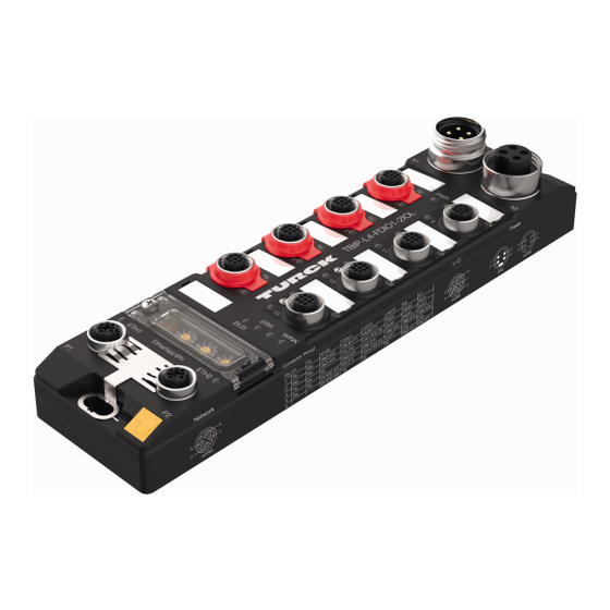
4.2 Device Overview
Visual representation of the device with key ports and dimensions.
4.3 Type Labels
Information on product identification codes and manufacturer details.
4.4 Switches and Connectors
Explains the function of each connector and switch on the device.
4.5 Block Diagram
Illustrates the internal functional blocks and signal flow of the module.
5 Safety Function
5.1 Safe Status
Describes the device's state and input reporting in a safe condition.
5.2 Fatal Error
Lists conditions that trigger a fatal error and lead to the safe state.
6 Safety Planning
6.1 Prerequisites
Outlines essential steps for safety planning, including risk analysis and concept development.
6.2 Reaction Time
Discusses reaction times and factors influencing them in safety systems.
6.3 Safety Characteristic Data
Provides crucial safety parameters like PL, SIL, PFD, and MTTFd.
7 Operating Instructions
7.1 General
General guidelines for device operation and maintenance.
7.2 Before Operation
Details mounting, connecting, and configuring the device before use.
7.3 Operating
Explains LED indications, output behavior, and decommissioning procedures.
8 Appendix: Wiring Diagrams
8.1 Ethernet Wiring
Pin assignment details for Ethernet connections.
8.2 Supply Voltage Connections
Pinout diagrams for power supply connections for different models.
8.3 Safety Input Wiring
Pinout for safety input channels.
8.4 Safety In-/Output Wiring
Pinout for combined safety input/output channels.
8.5 DXP Connections
Pin configuration for DXP (standard in-/outputs).
8.6 IO-Link Connections
Pin configuration for IO-Link ports.
9 Appendix: Switching examples
9.1 Inputs
Schematics for connecting various input types.
9.2 Outputs
Schematics for safe PP and PM switching outputs.
Need help?
Do you have a question about the TBIP-L4-FDIO1-2IOL and is the answer not in the manual?
Questions and answers