
Subscribe to Our Youtube Channel
Related Manuals for turck TBPN-L FDIO1-2IOL Series


Summary of Contents for turck TBPN-L FDIO1-2IOL Series
- Page 1 Your Global Automation Partner TBPN-L…-FDIO1-2IOL Safety Block I/O Module User Manual...
- Page 2 Hans Turck GmbH & Co. KG | T +49 208 4952-0 | F +49 208 4952-264 | more@turck.com | www.turck.com...
-
Page 3: Table Of Contents
Explanation of symbols used .................. 10 Additional documents.................... 10 Feedback about these instructions................ 11 Notes on the Product ........................ 11 Product identification.................... 11 Scope of delivery ...................... 11 Turck service........................ 11 For Your Safety.......................... 12 Intended use........................ 12 3.1.1 Reasonably foreseeable misuse.................... 12 General safety notes ..................... 13 Residual risks (EN ISO 12100:2010)................ 13 Warranty and liability .................... 13... - Page 4 Deleting the memory chip (Erase Memory) ................. 76 9.5.4 Configuration transfer and module behavior .............. 77 10 Restarting after Device Exchange or Modification .............. 79 10.1 Changing a device...................... 79 Hans Turck GmbH & Co. KG | T +49 208 4952-0 | F +49 208 4952-264 | more@turck.com | www.turck.com...
- Page 5 10.1.1 Prerequisites for device replacement.................. 79 10.1.2 Procedure for device replacement .................. 79 11 Maintenance............................ 80 12 Decommissioning.......................... 80 13 Disposal .............................. 80 14 Technical Data........................... 81 14.1 General technical data.................... 81 14.2 Technical data – safety inputs.................. 82 14.3 Technical data – safety outputs.................. 83 TBPN-L…-FDIO1-2IOL – Standard DXP Channels................ 85 15 Description of the Standard DXP Channels................. 85 16 Connecting ............................ 86 16.1...
- Page 6 Eliminating parameterization errors .............. 120 26 Technical Data – IO-Link Channels.................... 121 27 Appendix: Approvals and Markings ................... 122 28 Turck Subsidiaries - Contact Information .................. 123 Hans Turck GmbH & Co. KG | T +49 208 4952-0 | F +49 208 4952-264 | more@turck.com | www.turck.com...
-
Page 7: Tbpn-L
Explanation of symbols used.................... 10 Additional documents ....................... 10 Feedback about these instructions................. 11 Notes on the Product ........................ 11 Product identification ...................... 11 Scope of delivery......................... 11 Turck service ........................ 11 For Your Safety ........................... 12 Intended use ........................ 12 3.1.1 Reasonably foreseeable misuse...................... 12 General safety notes...................... 13 Residual risks (EN ISO 12100:2010) ................. 13... - Page 8 Overview - complete module...................... 74 9.4.2 Process output data – safe I/O channels .................. 74 Using the configuration memory .................. 76 Hans Turck GmbH & Co. KG | T +49 208 4952-0 | F +49 208 4952-264 | more@turck.com | www.turck.com...
- Page 9 TBPN-L…-FDIO1-2IOL– Safe I/O Channels 9.5.1 Storing a configuration........................ 76 9.5.2 Loading a configuration from the memory chip.............. 76 9.5.3 Deleting the memory chip (Erase Memory) ................ 76 9.5.4 Configuration transfer and module behavior ................ 77 Restarting after Device Exchange or Modification.............. 79 10.1 Changing a device ...................... 79 10.1.1 Prerequisites for device replacement...................
-
Page 10: About These Instructions
The following additional documents are available online at www.turck.com: Data sheet EU Declaration of Conformity (current version) Safety Manual Approvals Hans Turck GmbH & Co. KG | T +49 208 4952-0 | F +49 208 4952-264 | more@turck.com | www.turck.com... -
Page 11: Feedback About These Instructions
M12 closure caps 7/8’’ blind caps (not suitable to guarantee IP67/IP69K) Turck service Turck supports you with your projects, from initial analysis to the commissioning of your applic- ation. The Turck product database under www.turck.com contains software tools for program- ming, configuration or commissioning, data sheets and CAD files in numerous export formats. -
Page 12: For Your Safety
The permanent use in liquids Modifications to the device It is not permitted to modify the technical function or the construction of the device. Hans Turck GmbH & Co. KG | T +49 208 4952-0 | F +49 208 4952-264 | more@turck.com | www.turck.com... -
Page 13: General Safety Notes
For connecting sensors and actuators in safety related applications only use the connectors C0…C3 or X0…X3. Change the default password of the integrated web server after the first login. Turck recom- mends using a secure password. Residual risks (EN ISO 12100:2010) The wiring proposals described in the following have been tested under operational conditions with the greatest care. -
Page 14: Directives And Standards
Observe national and international regulations for explosion protection. Use the device only within the permissible operating and ambient conditions (see approval data and Ex approval specifications). Hans Turck GmbH & Co. KG | T +49 208 4952-0 | F +49 208 4952-264 | more@turck.com | www.turck.com... -
Page 15: Atex And Iecex Approval Requirements For Use In Ex Area
ATEX and IECEx approval requirements for use in Ex area Only use the device in an area with no more than pollution degree 2. Only disconnect and connect circuits when no voltage is applied. Only operate the switches if no voltage is present. Connect the metal protective cover to the equipotential bonding in the Ex area. -
Page 16: Product Description
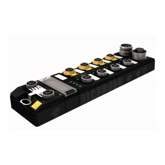
24 [0.95] Ø 6.4 [0.25] Ø 6.3 [0.25] 6 [0.24] 60.4 [2.38] 217.9 [8.58] 230.4 [9.07] mm [Inch] Fig. 2: TBPN-LL-FDIO1-2IOL Hans Turck GmbH & Co. KG | T +49 208 4952-0 | F +49 208 4952-264 | more@turck.com | www.turck.com... -
Page 17: Type Label
4.1.1 Type label TBPN-L1-FDIO1-2IOL Ident-No.: 6814053 Hans Turck GmbH & Co. KG D-45466 Mülheim a. d. Ruhr Charge code: www.turck.com YoC: Made in Germany Fig. 3: Type label TBPN-L1-FDIO1-2IOL TBPN-LL-FDIO1-2IOL Ident-No.: 100029879 Hans Turck GmbH & Co. KG D-45466 Mülheim a. d. Ruhr Charge code: www.turck.com... -
Page 18: Switches And Connectors
IOL, IO-Link port 2 (safe shutdown via FSO 1 possible) F-Address Rotary coding switch for address setting for PROFIsafe (F-address setting) Ethernet 1 Ethernet 2 Functional earth Hans Turck GmbH & Co. KG | T +49 208 4952-0 | F +49 208 4952-264 | more@turck.com | www.turck.com... -
Page 19: Functions And Operating Modes
Functions and operating modes 4.3.1 Safety function The TBPN-L…-FDIO1-2IOL provides two safe digital SIL3 inputs (FDI) and two SIL3-connectors (FDX), configurable as in- or outputs. The following devices can be connected to the safety inputs: 1- and 2-channel safety switches and sensors Contact based switches, e.g. -
Page 20: Safety Outputs (Fdo)
Turck Safety Configurator. It allows to transfer the configuration of one device to another device, e. g. for device exchange. Hans Turck GmbH & Co. KG | T +49 208 4952-0 | F +49 208 4952-264 | more@turck.com | www.turck.com... -
Page 21: Installing
Installing Installing the device in Zone 2 and Zone 22 In Zone 2 and Zone 22, the devices can be used in conjunction with the protective housing set TB-SG-L (ID 100014865). DANGER Potentially explosive atmosphere Risk of explosion through spark ignition For use in Zone 2 and Zone 22: „... -
Page 22: Mounting Onto A Mounting Plate
Fig. 6: Equivalent wiring diagram and shielding concept – TBPN-L1-FDIO1-2IOL 4 x 15 nF 1 nF 2,2 MΩ Fig. 7: Equivalent wiring diagram and shielding concept – TBPN-LL-FDIO1-2IOL Hans Turck GmbH & Co. KG | T +49 208 4952-0 | F +49 208 4952-264 | more@turck.com | www.turck.com... -
Page 23: Shielding Of The Fieldbus And I/O Level
5.3.2 Shielding of the fieldbus and I/O level The fieldbus and the I/O level of the modules can be grounded separately. Fig. 8: Grounding clip (1), grounding ring (2) and metal screw (3) The grounding ring (2) is the module grounding. The shielding of the I/O level is permanently connected to the module grounding. - Page 24 With mounted grounding clip: The shielding of the fieldbus is connected to the reference potential of the installation via the module grounding of the I/O level. Hans Turck GmbH & Co. KG | T +49 208 4952-0 | F +49 208 4952-264 | more@turck.com | www.turck.com...
-
Page 25: Connecting
Connecting WARNING Intrusion of liquids or foreign bodies through leaking connections Danger to life due to failure of the safety function „ Tighten M12 connectors with a tightening torque of 0.6 Nm. „ Tighten 7/8” connectors with a tightening torque of 0.8 Nm. „... -
Page 26: Connecting The M12 Connectors
0.4…1.0 Nm Turck Line + BUS M8 (SW9) M12 for bus cables (SW13) M12 for sensor cables (SW14) Hans Turck GmbH & Co. KG | T +49 208 4952-0 | F +49 208 4952-264 | more@turck.com | www.turck.com... -
Page 27: Connecting The Device To Ethernet
Connecting the device to Ethernet For the connection to Ethernet the device has an integrated auto-crossing switch with two 4- pole, D-coded M12 ×1-Ethernet-connectors. The maximum tightening torque is 0.6 Nm. TBPN-L1 Fig. 13: M12 Ethernet connector „ Connect the device to Ethernet according to the pin assignment below. „... -
Page 28: Connecting The Power Supply
System supply: power supply 1 (incl. supply of electronics) Load voltage: power supply 2, fed through, not used in device Hans Turck GmbH & Co. KG | T +49 208 4952-0 | F +49 208 4952-264 | more@turck.com | www.turck.com... - Page 29 We recommend the use of pre-assembled 5-pin power supply cables e.g. RK- P56PLB-1-RSP56PLB/TXG (not suitable for Ex use). Suitable cables can be found on www.turck.com. For the connection to the power supply, the device has two 5-pin, L coded M12 connectors. V1 and V2 are galvanically isolated.
-
Page 30: Supply (Selv/Pelv)
WARNING Potential differences Dangerous additions of voltages „ Avoid potential differences between internal and external load voltage supplies (24 VDC). Hans Turck GmbH & Co. KG | T +49 208 4952-0 | F +49 208 4952-264 | more@turck.com | www.turck.com... -
Page 31: Connecting Safe Sensors And Actuators
Connecting safe sensors and actuators NOTE We recommend pre-assembled 5-pin sensor cables. Suitable cables can be found on www.turck.com. The device has M12 connectors for connecting safe sensors and actuators. The maximum tight- ening torque is 0.6 Nm. Safety inputs (FDI) Fig. 21: M12 connector, safety inputs (FDI) - Page 32 FDO-/FDI (T2) Digital output (M)/digital input 2 GND (V1) Ground V1 FDO+/FDI (T1) Digital output (P)/digital input 1 Test pulse 2 Hans Turck GmbH & Co. KG | T +49 208 4952-0 | F +49 208 4952-264 | more@turck.com | www.turck.com...
-
Page 33: Switching Examples
Switching examples 6.6.1 Inputs Safe equivalent input for potential-free contacts (normally closed/normally closed) 1 T1 TB…-L…-… 1 T1 TB…-L…-… 2 FDI (T2) 2 FDI (T2) 3 n.c. 3 n.c. 4 FDI (T1) 4 FDI (T1) 5 T2 5 T2 Connected in the switch Two individual switches switching simultan- eously via one application Safe antivalent input for potential-free contacts (normally closed/normally closed) -
Page 34: Outputs
M con- 2 FDO – nector of the respective output (pin 2). 3 n.c. 4 FDO + 5 n.c. Hans Turck GmbH & Co. KG | T +49 208 4952-0 | F +49 208 4952-264 | more@turck.com | www.turck.com... -
Page 35: Commissioning
„ Check if the device works properly or if errors are displayed by controlling the diagnostics an status displays. 7.1.2 Configuring in Turck Safety Configurator „ Configure the device as described in chapter “Configuring” [} 39]. 7.1.3 Commissioning the device at the PLC „... -
Page 36: Reaction Time
PROFIsafe > local output 25 ms EN 61508 Local input > PROFIsafe 20 ms Local input <> local output 35 ms Hans Turck GmbH & Co. KG | T +49 208 4952-0 | F +49 208 4952-264 | more@turck.com | www.turck.com... -
Page 37: Addressing The Device
Addressing the device 7.3.1 Setting the F address at the device „ Open the cover above the switches. „ Set the F address via the three rotary coding switches under the cover at device. „ Execute a power cycle. DANGER Intrusion of liquids or foreign bodies through open cover Danger to life due to failure of the safety function „... - Page 38 For this, the PC used for configuration must be in the same IP network as the device itself. Hans Turck GmbH & Co. KG | T +49 208 4952-0 | F +49 208 4952-264 | more@turck.com | www.turck.com...
-
Page 39: Configuring
Configuring Installing Turck Safety Configurator The Turck Safety Configurator is available for download as zip archive on www.turck.com. NOTE A coupon code is required to download the software. The coupon code can be re- quested from Turck customer service. Further information can be found on the product page of the software. -
Page 40: Licensing Turck Safety Configurator
If the coupon code If missing, please order a coupon code via E-mail under the following E-mail address: TM-BWSoftwareSupport@turck.com NOTE The software can only be used on a virtual machine with Internet access. Hans Turck GmbH & Co. KG | T +49 208 4952-0 | F +49 208 4952-264 | more@turck.com | www.turck.com... -
Page 41: Creating A Configuration With The Tsc Commissioning Wizard
Creating a configuration with the TSC Commissioning wizard „ Start the software. Turck Safety Configurator starts with the Start assistant, which will lead through the first steps after program start. 8.4.1 Creating a new workspace „ In the start assistant, select option New workspace, enter a name and a storage location and create the new workspace with Create. - Page 42 Complete the configuration with OK. The basic configuration is applied. The release cicuits of the basic configuration are automtically created. Hans Turck GmbH & Co. KG | T +49 208 4952-0 | F +49 208 4952-264 | more@turck.com | www.turck.com...
- Page 43 Release circuits (OSSDs) of the basic configuration In the basic configuration, the release circuits OSSD1…OSSD4 and OSSD63 and OSSD64 are predefined as follows: Release circuit (OSSD) Channels OSSD 1 FSO0 OSSD 2 FSO1 OSSD 3 FDX4/5 OSSD 4 FDX6/7 … …...
-
Page 44: Adapting The Configuration Of The Safe Channels
Fig. 32: TSC – expert settings NOTE The description of the functions is part of the online help of the Turck Safety Config- urator. Hans Turck GmbH & Co. KG | T +49 208 4952-0 | F +49 208 4952-264 | more@turck.com | www.turck.com... - Page 45 Example configuration Fig. 33: TSC – expert settings (example configuration) Con- Channels Type I/O type Later function (see application ex- nector (Expert setting) ample [} 54]) at device FDI0/1 E-stop Safe input (dry contact), double Safely switches off output at channel forced FDX4/5.
- Page 46 The global error unlock can also be executed via the process data bit ”UNLK” in the device process output data. Hans Turck GmbH & Co. KG | T +49 208 4952-0 | F +49 208 4952-264 | more@turck.com | www.turck.com...
- Page 47 Complete the hardware configuration in the start assistant „ Close the dialog box hardware configuration with OK. The release circuits for the hardware configuration (example configuration) are created. Fig. 35: TSC – release circuits (example configuration) Channels Type OSSD Adaptation FDI0/1 E-stop 64.
-
Page 48: Loading The Configuration With The Tsc Commissioning Wizard
Loading the configuration with the TSC commissioning wizard „ Start the commissioning wizard and click Next >. Fig. 36: TSC – start the commissioning wizard Hans Turck GmbH & Co. KG | T +49 208 4952-0 | F +49 208 4952-264 | more@turck.com | www.turck.com... - Page 49 „ In the dialog Commissioning wizard settings, enter the Name of the validator and the Password for safety monitors (release password) and confirm with OK. Fig. 37: TSC – Commissioning wizard, assigning a password The connected TBPN-L…-FDIO1-2IOL is prepared for the configuration download. Fig. 38: TSC –...
- Page 50 Confirm with OK and store the setting in the project (store the interface in the work- space). The configuration is sent to the TBPN-L…-FDIO1-2IOL. This process may take a few seconds. Hans Turck GmbH & Co. KG | T +49 208 4952-0 | F +49 208 4952-264 | more@turck.com | www.turck.com...
- Page 51 The configuration protocol is created. Fig. 40: TSC – commissioning wizard configuration protocol „ Check the configuration using the configuration protocol and confirm the check. Fig. 41: TSC – confirming check of the configuration protocol V02.00 | 2021/11...
- Page 52 Fig. 42: TSC – release configuration The configuration has been released. Fig. 43: TSC – release configuration „ Click OK and complete the commissioning with Finish. Hans Turck GmbH & Co. KG | T +49 208 4952-0 | F +49 208 4952-264 | more@turck.com | www.turck.com...
- Page 53 The Turck Safety Configurator changes to the online mode and opens the diagnostics configuration. Fig. 44: TSC – Diagnostics configuration (online, not communication to safety PLC) V02.00 | 2021/11...
-
Page 54: Application Example - Configuring A Safety Function In Tsc
In the dialog box State of output switching element x select OSSD 63 under Assignment. Fig. 45: TSC – 3. OSSD, state of output switching element OSSD 63 Hans Turck GmbH & Co. KG | T +49 208 4952-0 | F +49 208 4952-264 | more@turck.com | www.turck.com... - Page 55 „ Select the device State of output switching element from the device library and place it at the function input. In the dialog box State of output switching element x select OSSD 64 under Assignment. Fig. 46: TSC – 3. OSSD, state of output switching element OSSD 63 and OSSD 64 The activation of the emergency shutdown at FDI0/1 or the light grid at FDI2/3 switches off output FDX4/5.
- Page 56 Fig. 47: TSC – 4. OSSD, state of output switching element OSSD 3 The state of OSSD 3 controls the output FDX6/7 in OSSD 4. Hans Turck GmbH & Co. KG | T +49 208 4952-0 | F +49 208 4952-264 | more@turck.com | www.turck.com...
- Page 57 Release of the safety function via a release bit in the F-CPU The release of the safety function is done using a release bit in the F-CPU. Therefore, an output bit of the F-CPU is assigned to the output function in the 3. OSSD. „...
- Page 58 „ Open the Output assignment and assign a PROFIsafe bit to output FDX4/5. Fig. 49: TSC – output assignment PROFIsafe bit Hans Turck GmbH & Co. KG | T +49 208 4952-0 | F +49 208 4952-264 | more@turck.com | www.turck.com...
-
Page 59: Checking And Loading The Configuration
8.6.1 Checking and loading the configuration The Turck Safety Configurator checks the created configuration for logical errors, which means, the logical wiring of the single components in the release circuits is checked. The configuration check does not consider double allocation etc. -
Page 60: Configuring Single Channel Safety Sensors
If a slot is configured as Single channel safety in Turck Safety Configurator, then the double channel function for the slot is disabled. Fig. 51: TSC – single channel inputs Hans Turck GmbH & Co. KG | T +49 208 4952-0 | F +49 208 4952-264 | more@turck.com | www.turck.com... - Page 61 No release circuits are generated for the single channel inputs. The OSSDs have to be created manually. „ Create an OSSD by using the New window function. Fig. 52: TSC – creating a new window „ Add a Single channel safety input from the device catalog to the new window. Unused channels are displayed in bold.
- Page 62 Link the single channel safe input with an Input F-CPU. Fig. 54: TSC – linking a single channel safe input with the PLC Hans Turck GmbH & Co. KG | T +49 208 4952-0 | F +49 208 4952-264 | more@turck.com | www.turck.com...
- Page 63 „ Add an automatic start and assign a PROFIsafe bit in order to be able to monitor the single channel sensor from the PLC. Fig. 55: TSC – single channel safe input with automatic start and PROFIsafe assignment V02.00 | 2021/11...
-
Page 64: Configuring The Device At Profinet/Profisafe In Tia Portal
Adding the device via GSDML „ Install the device's GSDML-file. „ Add device to PROFINET-IO-System (100). Fig. 56: Adding the TBPN-L…-FDIO1-2IOL to PROFINET. Hans Turck GmbH & Co. KG | T +49 208 4952-0 | F +49 208 4952-264 | more@turck.com | www.turck.com... - Page 65 Fig. 57: Slots of TBPN-L…-FDIO1-2IOL The function of these slots is either pre-defined via GSDML or can only be used for a specific purpose. Module Name turck-tbpn-l1-fdio1-2iol Main module, parameterization of parameters (deactivation of (default name) protocols, etc.) which concern the complete device. PN-IO Parameterization of PROFINET functions (MRP, etc.) and the...
- Page 66 F address of TBPN-L…-FDIO1-2IOL, in this example: address 105 F_iPar_CRC CRC from the protocol in the Turck Safety Configurator, in this example: 9263. Fig. 58: F_parameters of TBPN-L…-FDIO1-2IOL Hans Turck GmbH & Co. KG | T +49 208 4952-0 | F +49 208 4952-264 | more@turck.com | www.turck.com...
-
Page 67: Operating
Operating LED displays The device has the following LED indicators: Power supply Group and bus errors Status Diagnostics LED PWR Meaning No voltage connected or under voltage at V1 Green Voltage V1 and V2 OK No valid state, device switches to the safe state Red/green No valid state, device switches to the safe state LED 0…3... -
Page 68: Status- And Control Word
V1 too low (< 18 VDC) Control word The control word is not in use. Hans Turck GmbH & Co. KG | T +49 208 4952-0 | F +49 208 4952-264 | more@turck.com | www.turck.com... -
Page 69: Process Input Data
Process input data This chapter contains the description of the process input data of the safe I/O channels. The process input data of the IO-Link channels and the universal standard I/O channels are not safety-relevant and are only presented for the sake of completeness. The detailed description of the process data of the non-safety relevant channels can be found in the second and third parts of the operating manual. -
Page 70: Process Input Data - Safe I/O Channels
Safe Status connector C1/X1 TEST WAIT … … n + 19 Connector C7/X7 TEST WAIT n + 20… Reserved n + 23 Hans Turck GmbH & Co. KG | T +49 208 4952-0 | F +49 208 4952-264 | more@turck.com | www.turck.com... - Page 71 PROFIsafe status byte Bit 7 Bit 6 Bit 5 Bit 4 Bit 3 Bit 2 Bit 1 Bit 0 reserved Cons_nr_R Toggle_d FV activ- CE_CRC Device iPar_OK ated time-out error Name Meaning iPar_OK The bit is set if new parameter values have been assigned to TBPN-L…- FDIO1-2IOL.
- Page 72 Name Code Meaning No memory chip plugged NCNF No configuration available CNFMM Configuration mismatch COMLO Communication loss FERR Fatal Error Hans Turck GmbH & Co. KG | T +49 208 4952-0 | F +49 208 4952-264 | more@turck.com | www.turck.com...
- Page 73 Status output bits of the TBPN-L…-FDIO1-2IOL which can be used as input sig- FBO0-7 nals for the non part of the higher level control. These bits have to be configured by the user in Turck Safety Configurator. V02.00 | 2021/11...
-
Page 74: Process Output Data
PROFIsafe checksum (CRC) n + 7 n + 8 Unlock Safe Unit [} 75] UNLK n + 9 PROFINET output data Hans Turck GmbH & Co. KG | T +49 208 4952-0 | F +49 208 4952-264 | more@turck.com | www.turck.com... - Page 75 FBI 0-2 FBI 0-1 FBI 0-0 Name Meaning FIB 0-0… These four bits are sent via the field bus to the TBPN-L…-FDIO1-2IOL and can be FBI0-7 configured in the Turck Safety Configurator as field bus bits (inputs). V02.00 | 2021/11...
-
Page 76: Using The Configuration Memory
Execute a power cycle at the device. The content of the memory chip is deleted. The procedure completed as soon as the ERR LED stops blinking. Hans Turck GmbH & Co. KG | T +49 208 4952-0 | F +49 208 4952-264 | more@turck.com | www.turck.com... -
Page 77: Configuration Transfer And Module Behavior
Turck Safety Configurator to delete the content of the memory stick. Fig. 59: Deleting the configuration via Turck Safety Configurator The configuration on the memory chip is deleted. The procedure completed as soon as the ERR LED stops blinking. - Page 78 During operation ing operation Ò The new configuration is checked. Ò Loading the configura- tion from the memory to the device Hans Turck GmbH & Co. KG | T +49 208 4952-0 | F +49 208 4952-264 | more@turck.com | www.turck.com...
-
Page 79: Restarting After Device Exchange Or Modification
Restarting after Device Exchange or Modification 10.1 Changing a device DANGER Mounting or unmounting under voltage Personal damage due to unintentional machine start „ Mount or unmount the device only in a de-energized condition. 10.1.1 Prerequisites for device replacement The replacement device has to be a device of the same type with the identical or a higher device version. -
Page 80: Maintenance
Defective or faulty devices must not, in any event, be put back into circulation. Send the devices back to Turck for testing and disposal. Hans Turck GmbH & Co. KG | T +49 208 4952-0 | F +49 208 4952-264 | more@turck.com | www.turck.com... -
Page 81: Technical Data
Technical Data 14.1 General technical data Devices TBPN-L1-FDIO1-2IOL 6814053 According to device labeling TBPN-LL-FDIO1-2IOL 100029879 According to device labeling Power supply Connector TBPN-L1-FDIO1-2IOL 7/8", 5-pin TBPN-LL-FDIO1-2IOL M12, L coded, 5-pin V1 (incl. electronics supply) 24 VDC 24 VDC, only through connected Permissible range 20.4…28.8 VDC Isolation voltages... -
Page 82: Technical Data - Safety Inputs
Test pulse, typ. 0.6 ms Test pulse max. 0.8 ms Interval between two test 900 ms (for static inputs) pulses, min. Hans Turck GmbH & Co. KG | T +49 208 4952-0 | F +49 208 4952-264 | more@turck.com | www.turck.com... -
Page 83: Technical Data - Safety Outputs
14.3 Technical data – safety outputs Safety outputs Suitable for inputs according to EN 61131-2, type 1 Output level in OFF-state < 5 V Output level in OFF-state < 1 mA Test pulse resistive load, max. 0.5 ms Test pulse max. 1.25 ms Interval between two test 500 ms... -
Page 84: Tbpn-L
18.2.1 Overview - complete module...................... 90 18.2.2 Process output data – standard DXP channels ................. 90 Technical Data – DXP Channels.................... 91 Hans Turck GmbH & Co. KG | T +49 208 4952-0 | F +49 208 4952-264 | more@turck.com | www.turck.com... -
Page 85: Description Of The Standard Dxp Channels
Description of the Standard DXP Channels The TBPN-L…-FDIO1-2IOL has two standard DXP channels. Fig. 60: Device structure – DXP channels TBPN-L1 TBPN-LL Meaning Power IN Power OUT FDI0/1, safety-related input FDI2/3, safety-related input FDX4/5, safety-related input FDX6/7, safety-related input DXP8/9, standard in-/outputs (safe shutdown via FSO0 possible) DXP10/11, standard in-/outputs (safe shutdown via FSO0 possible) -
Page 86: Connecting
1 = FSO0 2 = DI/DO 3 = GND (V1) 4 = DI/DO 5 = FE Fig. 62: Pin assignment C4…C5 or X4…X5 Hans Turck GmbH & Co. KG | T +49 208 4952-0 | F +49 208 4952-264 | more@turck.com | www.turck.com... -
Page 87: Configuring
Configuring 17.1 Parameters The default values are written in bold. Parameter name Value Meaning Description Manual output reset after The output switches on automatically after overcurrent (SRO…) an overload. After an overcurrent, the output switches on again only after resetting and switching on again. -
Page 88: Operating
+ 96… IO-Link Events [} 105] n + 159 Module status n + 160… Module status [} 68] n + 161 Hans Turck GmbH & Co. KG | T +49 208 4952-0 | F +49 208 4952-264 | more@turck.com | www.turck.com... -
Page 89: 18.1.2 Process Input Data - Standard Dxp Channels
18.1.2 Process input data – standard DXP channels Byte no. Bit 7 Bit 6 Bit 5 Bit 4 Bit 3 Bit 2 Bit 1 Bit 0 Basic n + 1 DXP11 DXP10 DXP9 DXP8 FBI1-3 FBI1-2 FBI1-1 FBI1-0 C5/X5P2 C5/X5P4 C4/X4P2 C4/X4P4 …... -
Page 90: Process Output Data
Value Meaning DXP… Output inactive C… = connector C…P… C0…C7 (TBEN-L4 or TBEN-L5) Output active X0…X7 (TBEN-LL) P …= pin Hans Turck GmbH & Co. KG | T +49 208 4952-0 | F +49 208 4952-264 | more@turck.com | www.turck.com... -
Page 91: Technical Data - Dxp Channels
Technical Data – DXP Channels The first section of the operating instructions contains the general technical data of the device [} 81]. Technical data Digital inputs Number of channels Input type Switching threshold EN 61131-2 type 3, PNP Operating current < 100 mA Signal voltage low level <... -
Page 92: Tbpn-L
24.8.4 Parameter ”Data storage mode” = deactivated, clear............ 120 Troubleshooting ........................ 120 25.1 Eliminating parameterization errors................ 120 Technical Data – IO-Link Channels .................. 121 Hans Turck GmbH & Co. KG | T +49 208 4952-0 | F +49 208 4952-264 | more@turck.com | www.turck.com... -
Page 93: Description Of The Io-Link Channels
Description of the IO-Link Channels The TBPN-L…- FDIO1-2IOL provides two IO-Link ports at the connectors C6 and C7 (TBPN-L1) or X6 and X7 (TBPN-LL). 2-channel IO-Link master according to specification V1.1 two universal digital channels, PNP, channel diagnostics, 0,5 A Fig. 63: Device structure –... -
Page 94: Connecting
Fig. 65: Pin assignment IO-Link port IOL1 (C6 or X6) Signal Meaning Class A supply DI/DO Digital input or digital output/Class B supply GND (V1) Ground V1 Hans Turck GmbH & Co. KG | T +49 208 4952-0 | F +49 208 4952-264 | more@turck.com | www.turck.com... - Page 95 Signal Meaning IO-Link GND (V1) Functional earth Fig. 66: M12 connector, IO channels IOL2, C7 or X7 „ Connect the IO-Link devices to the device according to the pin assignment. 1 = FSO1 2 = DI/DO 3 = GND (V1) 4 = C/Q 5 = GND (V1) Fig. 67: Pin assignment IO-Link port IOL2 (C7 or X7) Signal...
-
Page 96: Commissioning
Fig. 68: Reset device to factory settings via DTM (example) „ Connect the IO-Link V1.1 device. The LED IOL at the IO-Link port is green, IO-Link communication active. Hans Turck GmbH & Co. KG | T +49 208 4952-0 | F +49 208 4952-264 | more@turck.com | www.turck.com... - Page 97 Delete the data storage memory via parameters „ Set Data storage mode to deactivated, clear. „ Load the parameter changes into the device. „ Re-activate the data storage, if necessary. „ Load the parameter changes into the device. „ Connect the IO-Link V1.1 device. The LED IOL at the IO-Link port is green, IO-Link communication active.
-
Page 98: Configuring
Device ID (LSB) Device ID Device ID Device ID (MSB) IOL2 20…35 Assignment similar to IOL1 (byte 4 to 19) Hans Turck GmbH & Co. KG | T +49 208 4952-0 | F +49 208 4952-264 | more@turck.com | www.turck.com... - Page 99 Meaning of parameter bits The default values are written in bold. Parameter name Value Meaning Description dec. Hex. Operation mode 0x00 IO-Link without valida- Pin 4 is operated in IO-Link mode. The master does not check if the connected device tion matches the configured one.
- Page 100 (PDIN in- message is generated. valid) 0x01 No diagnostic generated Invalid process data do not cause a diagnostic mes- sage. Hans Turck GmbH & Co. KG | T +49 208 4952-0 | F +49 208 4952-264 | more@turck.com | www.turck.com...
- Page 101 Parameter name Value Meaning Description dec. Hex. Deactivate Influences the sending of IO-Link-Events from the master to the fieldbus. Depending on the diagnostics parameterization, the master transmits Events based on their priority to the fieldbus or not. 0x00 No The master transmits all IO-Link Events to the field- bus.
-
Page 102: 23.1.1 Adapting Process Data Mapping
PLC. The process data mapping is determined channel by channel through the parameters process input data mapping and process output data mapping. Hans Turck GmbH & Co. KG | T +49 208 4952-0 | F +49 208 4952-264 | more@turck.com | www.turck.com... -
Page 103: Operating
Operating 24.1 LED displays – IO-Link channels LED IOL, Meaning (Channel in IO-Link-mode) LED 12 (C6/X6), LED14 (C7/X7) Port inactive, no IO-Link communication, diagnostics deactivated Green flashing IO-Link communication, process data valid Red flashing IO-Link communication and module error, invalid process data IO-Link supply error free, no IO-Link communication and/ or module error, process data invalid LED IOL,... -
Page 104: Process Input Data
+ 96… IO-Link Events [} 105] n + 159 Module status n + 160… Module status [} 68] n + 161 Hans Turck GmbH & Co. KG | T +49 208 4952-0 | F +49 208 4952-264 | more@turck.com | www.turck.com... -
Page 105: 24.2.2 Process Input Data - Io Link Channels
24.2.2 Process input data – IO Link channels Byte no. Bit no. Basic DXP15 DI14 DXP13 DI12 C7/X7P2 C7/X7P4 C6/X6P2 C6/X6P4 n + 1 n + 2 DVS14 DVS12 n + 3… … n + 23 IO-Link process input data n + 24 IOL1 process input data (C6/X6) …... - Page 106 Overcurrent at output (DXP channel used as output) s. ”Software diagnostic messages”, [} 108] IO-Link port diagnostics s. ”IO-Link Events”, [} 112] IO-Link Events Hans Turck GmbH & Co. KG | T +49 208 4952-0 | F +49 208 4952-264 | more@turck.com | www.turck.com...
-
Page 107: Process Output Data
24.3 Process output data 24.3.1 Overview - complete module The process output data of TBPN-L…-FDIO1-2IOL are structured as follows: Byte no. Bit 7 Bit 6 Bit 5 Bit 4 Bit 3 Bit 2 Bit 1 Bit 0 n + 0… Basic n + 1 Control: DXP channels [} 90]... -
Page 108: Software Diagnostic Messages
The connected device does not match the channel configuration or there is no device connected to the channel. This diagnostic message depends on the para- meterization of the channel. Hans Turck GmbH & Co. KG | T +49 208 4952-0 | F +49 208 4952-264 | more@turck.com | www.turck.com... - Page 109 Meaning DSER Data storage error Possible causes: Data storage mismatch: IO-Link device in accordance with IO-Link V1.0 connected. The data storage buffer contains data of another device. Overflow of the data storage buffer The connected device may be locked for parameter changes or for data stor- age.
-
Page 110: 24.4.1 Profinet Diagnostics
Similar to IO-Link - port 1 DI14 C7/X7 (C/Q) 24.5 FSU - Fast Start-Up (prioritized startup) Fast Start-Up is not supported by the device. Hans Turck GmbH & Co. KG | T +49 208 4952-0 | F +49 208 4952-264 | more@turck.com | www.turck.com... -
Page 111: Specific Configuration Of The Io-Link Ports Via Gsdml (Sidi)
Specific configuration of the IO-Link ports via GSDML (SIDI) Simple IO-Link Device Integration (SIDI) Turck's Simple IO-Link Device Integration (SIDI) simplifies the handling of IO-Link devices in PROFINET engineering systems. The devices are integrated in the GSDML file of the master,... -
Page 112: Port Functions For Port 0 (Io-Link Master)
2 byte Unsigned 16 DEVICE_ID 4 byte Unsigned 32 FUNCTION_ID 2 byte Unsigned 16 Value: 0 SERIAL_NUMBER 16 byte String Hans Turck GmbH & Co. KG | T +49 208 4952-0 | F +49 208 4952-264 | more@turck.com | www.turck.com... - Page 113 Subindex 65: IO-Link Events The object reads IO-Link Event diagnostics. Entity_Port IO-Link sub index Read/write Length Read 255 byte NOTE Only ”appears” (coming diagnostics) and ”Single Shot Events” are shown, as long as they are pending. Structure of the read data: Byte 0 contains 2 bit per IO-Link port which show, if the process data of the connected device are valid or not.
- Page 114 Structure of the Teach command: Byte 0 0x00 Teach all ports 0x01 Teach port 1 0x02 Teach port 2 0x03…0xFF Reserved Hans Turck GmbH & Co. KG | T +49 208 4952-0 | F +49 208 4952-264 | more@turck.com | www.turck.com...
- Page 115 Subindex 68: Master Port Scan Configuration The object reads the configuration of the IO-Link devices connected to the IO-Link master. 28 byte are returned per IO-Link port. Entity_Port IO-Link sub index Read/write Length Read Max. 120 byte Structure of the response telegram: IO-Link port Content Length...
- Page 116 (vendor ID, device ID, serial number) does not/do not match the data which are stored in the master for this device. Remedy: Change the device. Adapt the master parameterization Hans Turck GmbH & Co. KG | T +49 208 4952-0 | F +49 208 4952-264 | more@turck.com | www.turck.com...
-
Page 117: Using The Data Storage Mode
Device Status Value Meaning Device works correctly Maintenance Event Out-of-Specification Event Functional check Error 5…255 Reserved 24.8 Using the data storage mode Data storage mode NOTE Data storage mode is only available for devices complying with the IO-Link specifica- tion V1.1. In the IO-Link master, the data storage mode can be set using the parameter ”data storage mode”. -
Page 118: 24.8.1 Parameter "Data Storage Mode" = Activated
The parameter data of the defective device are transferred from the IO-Link master to the new IO-Link device. IOLM IOLD Fig. 72: Data storage mode activated – parameter set in the device unchanged Hans Turck GmbH & Co. KG | T +49 208 4952-0 | F +49 208 4952-264 | more@turck.com | www.turck.com... -
Page 119: 24.8.2 Parameter "Data Storage Mode" = Read In
IO-Link master. Turck IO-Link devices can be reset to factory settings via a system command using a generic IO-Link DTM and the device specific IODD. For the reset of third party devices, please read the corresponding manufacturer documentation. -
Page 120: 24.8.4 Parameter "Data Storage Mode" = Deactivated, Clear
IO-Link port with the gnosis if the process value can- parameter Process input data in- Ò not be measured. valid No diagnostic generated. Hans Turck GmbH & Co. KG | T +49 208 4952-0 | F +49 208 4952-264 | more@turck.com | www.turck.com... -
Page 121: Technical Data - Io-Link Channels
Technical Data – IO-Link Channels The first section of the operating instructions contains the general technical data of the device [} 81]. Technical data Supply Permissible range 20.4…28.8 VDC (acc. to IO-Link specification) Operating current < 120 mA Power supply of the IO-Link ports IO-Link port 1 at C6 or X6 VAUX1, max. -
Page 122: Appendix: Approvals And Markings
Power supply 24 VDC ±10 % Input current I 9 A (total per module) Output current I 1,5 A (per output) Hans Turck GmbH & Co. KG | T +49 208 4952-0 | F +49 208 4952-264 | more@turck.com | www.turck.com... -
Page 123: Turck Subsidiaries - Contact Information
Turck Subsidiaries - Contact Information Germany Hans Turck GmbH & Co. KG Witzlebenstraße 7, 45472 Mülheim an der Ruhr www.turck.de Turck Australia Pty Ltd Australia Building 4, 19-25 Duerdin Street, Notting Hill, 3168 Victoria www.turck.com.au Belgium TURCK MULTIPROX Lion d'Orweg 12, B-9300 Aalst www.multiprox.be... - Page 124 Árpád fejedelem útja 26-28., Óbuda Gate, 2. em., H-1023 Budapest www.turck.hu Turck Inc. 3000 Campus Drive, USA-MN 55441 Minneapolis www.turck.us Hans Turck GmbH & Co. KG | T +49 208 4952-0 | F +49 208 4952-264 | more@turck.com | www.turck.com...
- Page 125 Over 30 subsidiaries and over 60 representations worldwide! D301382 | 2021/11 D301382 www.turck.com...
Need help?
Do you have a question about the TBPN-L FDIO1-2IOL Series and is the answer not in the manual?
Questions and answers