
Related Manuals for optris CS


Summary of Contents for optris CS
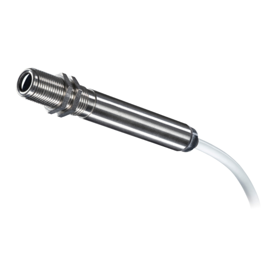
- Page 1 Operator’s Manual optris ® Infrared thermometer 1.800.561.8187 information@itm.com www. .com...
-
Page 2: Table Of Contents
Table of contents Table of contents Table of contents .............................. 3 General notes ............................7 Intended use ............................7 Warranty ............................. 8 Scope of delivery ..........................8 Maintenance ............................9 Technical Data ............................10 Default settings ..........................10 General specifications ........................13 Electrical specifications ........................ - Page 3 Close focus optics ..........................20 LED-Functions ..........................21 2.7.1 Automatic aiming support ......................21 2.7.2 Self-diagnostic .......................... 22 2.7.3 Temperature code indication ....................23 Installation ............................... 25 Mechanical Installation ........................25 3.1.1 Mounting accessories ....................... 26 3.1.2 Air purge collar .......................... 27 3.1.3 Other accessories ........................
- Page 4 Table of contents 3.2.2 Open collector output ........................ 34 3.2.3 Direct connection to a RS232 on the computer ................ 35 Schematic circuit diagrams for maintenance applications ..............36 IRmobile app ............................39 Software CompactConnect ........................41 Installation ............................41 Communication settings ........................43 6.2.1 Serial Interface ..........................
- Page 5 Appendix A – Table of emissivity for metals ....................48 Appendix B - Table of emissivity for non-metals ..................49 Appendix C – Direct connection to a RS232 interface ................50 Appendix D – Smart Averaging ........................52 Appendix E – Declaration of Conformity ...................... 53 1.800.561.8187 information@itm.com www.
-
Page 6: General Notes
® CS infrared thermometer. The sensors of the optris CS series are non-contact infrared temperature sensors. They calculate the surface temperature based on the emitted infrared energy of objects [►7 Basics of Infrared Thermometry The CS sensing head is a sensitive optical system. Please use only the thread for mechanical installation. -
Page 7: Warranty
If the failure results from misuse or neglect the user has to pay for the repair. In that case you may ask for a cost estimate beforehand. 1.3 Scope of delivery • CS incl. connection cable • Two mounting nuts • Quick start guide 1.800.561.8187... -
Page 8: Maintenance
General notes 1.4 Maintenance Blow off loose particles using clean compressed air. The lens surface can be cleaned with a soft, humid tissue (moistened with water) or a lens cleaner (e.g. Purosol or B+W Lens Cleaner). Never use cleaning compounds which contain solvents (neither for the lens nor for the housing). 1.800.561.8187 information@itm.com www. -
Page 9: Technical Data
2 Technical Data 2.1 Default settings Smart Averaging means a dynamic average adaptation at high signal edges. [Activation via software only]. [►Appendix D – Smart Averaging] The default settings can be changed with the optional IR App Connector (USB adapter cable & software). - Page 10 Gain 1.000/ Offset 0.0 Failsafe Inactive For a usage of the CS for online maintenance applications (in electrical cabinets e.g.) the following recommend settings are already included in the factory default setting (but not active): At 3-state output the following settings are default: Pre-alarm difference: 2 °C...
- Page 11 IN/ OUT At Alarm output (open collector) the following settings are default: Mode: normally closed Temp code output: activated (for values above alarm level) Range settings: 0 °C = 0 %/ 100 °C = 100 % Vcc adjust If activated the following settings are default: Output voltage range: 0-10 V Difference mode: activated...
-
Page 12: General Specifications
Technical Data 2.2 General specifications Environmental rating IP63 Ambient temperature -20...80 °C Storage temperature -40...85 °C Relative humidity 10...95 %, non-condensing Material Stainless steel Dimensions 85 mm, M12x1 Weight 58 g Cable length 1 m (Standard), 3 m, 8 m, 15 m Cable diameter 4.3 mm Vibration... -
Page 13: Electrical Specifications
2.3 Electrical specifications Used Pin Function IN/ OUT Analog 0-5 V or 0-10 V / scalable Alarm output voltage adjustable; N/O or N/C Alarm 3-state alarm output (three voltage level for no alarm, pre-alarm, alarm) Analog programmable open collector output (NPN type) [0-30 V DC/ 50 mA] Temp. - Page 14 500 mA if the mV output is not used High level: > 0.8 V/ Low level: < 0.8 V The CS sensor may only be powered either via USB or externally, but not simultaneously! Power supply [white]...
-
Page 15: Measurement Specifications
2.4 Measurement specifications Temperature range -50...1030 °C (scalable via Software) Spectral range 8...14 µm Optical resolution 15:1 CF-lens (optional) 0.8 mm@ 10 mm Accuracy ±1.5 °C or ±1.5 % of reading (whichever is greater) 1) 2) Repeatability ±0.75 °C or ±0.75 % of reading (whichever is greater) Temperature coefficient ±0.05 K/ K or ±0.05 %/ K (whichever is greater) Temperature resolution (NETD) -
Page 16: Optical Charts
Technical Data Software / App optional (CompactConnect / IRmobile) at ambient temperature 23 5 °C and object temperatures >0 °C Accuracy for thermocouple output: ±2.5°C or ±1% for ambient temperatures <18 °C and >28 °C at time constant of 200 ms and an object temperature of 200 °C 2.5 Optical charts The size of the measuring object and the optical resolution of the infrared thermometer •... - Page 17 As an alternative to the optical diagrams, the spot size calculator can also be used on the Optris website (https://www.optris.global/spot-size-calculator) or via the Optris calculator app. The app can be downloaded for free from the Google Play store (see QR code).
- Page 18 Technical Data Figure 1: Optical chart CS (15:1) Figure 2: Optical chart CS (15:1) with CF-lens (0.8 mm@ 10 mm) 1.800.561.8187 information@itm.com www. .com...
-
Page 19: Close Focus Optics
2.6 Close focus optics If the CF-lens is used, the transmission has to be set to 0.78. To change this value the • optional USB-Kit (including software) is necessary. The assigned transmission (average value) is a characteristic value which may has a certain •... -
Page 20: Led-Functions
LED Alarm LED lights up if the object temperature exceeds or deceeds an alarm threshold Automatic aiming support Sighting feature for an accurate aiming of the CS to hot or cold objects Self-diagnostic LED is indicating different states of the sensor... -
Page 21: Self-Diagnostic
2.7.2 Self-diagnostic At a supply voltage (Vcc) ≥ 12 V it takes about 5 minutes until the sensor works in a stable mode. Therefore, after switching on the unit, the LED will show a not stable state for up to 5 minutes. -
Page 22: Temperature Code Indication
Technical Data Sensor overheated The internal temperature probes have detected an invalid high internal temperature of the CS. Out of meas. range The object temperature is out of measuring range. Not stable The internal temperature probes have detected an unequally internal temperature of the CS. - Page 23 Examples 87 °C 8-times long flashing indicates and afterwards 7-times short flashing indicates 31 °C 3-times long flashing indicates and afterwards 1-time short flashing indicates 8 °C 10-times long flashing indicates and afterwards 8-times short flashing indicates 20 °C 2-times long flashing indicates and afterwards 10-times short flashing indicates 1.800.561.8187 information@itm.com...
-
Page 24: Installation
3 Installation 3.1 Mechanical Installation The CS is equipped with a metric M12x1 thread and can be installed either directly via the sensor thread or with the help of the both hex nuts (standard) to the mounting bracket available. Figure 6: Dimensions CS For an exact aiming of the sensor to an object the LED function ►2.7.1 Automatic aiming support can be... -
Page 25: Mounting Accessories
3.1.1 Mounting accessories The Mounting fork can be combined with the Mounting bracket [Order No.: ACCTFB] using the M12x1 thread. Figure 7: Mounting bracket, adjustable in one axis Figure 8: Mounting bolt with M12x1 thread, adjustable in [Order No.: ACCTFB] one axis [Order No.: ACCTMB] 1.800.561.8187 information@itm.com... -
Page 26: Air Purge Collar
Installation Figure 9: Mounting fork with M12x1 thread, adjustable in Figure 10: Mounting bracket, adjustable in two axes 2 axes [Order No.: ACCTMG] [Order No.: ACCTAB] 3.1.2 Air purge collar • Use oil-free, technically clean air only. The needed amount of air (approx. 2...10 l/ min.) depends on the application and the •... - Page 27 Figure 11: Standard air purge collar; fits to the mounting Figure 12: Laminar air purge collar – the side air outlet bracket; hose connection: 3x5 mm [Order No.: ACCSAP] prevents a cooling down of the object in short distances; hose connection: 3x5 mm [Order No.: ACCTAPL] Figure 13: A combination of the laminar air purge collar with the bottom section of the mounting fork allows an adjustment in two axes.
-
Page 28: Other Accessories
Installation 3.1.3 Other accessories If the protective window is used, the transmission has to be set to 0.83. To change this value the optional USB-Kit (including CompactConnect software) is necessary. Figure 14: Right angle mirror enables measurement with Figure 15: Protective window same mechanical size as 90°... -
Page 29: Tilt Assembly
Figure 16: IR App Connector: USB adapter cable incl. terminal block [Order No.: ACCSMIAC] 3.1.4 Tilt assembly With this mounting accessory a fine adjustment of the CS with an off-axis angle +/- 6.5° is possible. Figure 17: Tilt assembly [Order No.: ACCTTAS] 1.800.561.8187 information@itm.com... -
Page 30: Electrical Installation
Use shielded cables only. The sensor shield has to be grounded. • • The shield [black] on the CS is not connected to GND [brown].In any case it is necessary to connect the shield to ground or GND (whichever works best)! •... - Page 31 Figure 18: Analog device (mV output at OUT pin) Analog device (Thermocouple typ K at OUT t/c K pins) The output impedance must be ≥ 20 kΩ. Figure 19: Analog device (Thermocouple typ K at OUT t/c K pins) 1.800.561.8187 information@itm.com www.
-
Page 32: Digital Communication
Installation You can choose between an mV output (0-5 or 0-10 V; scalable via software) and a thermocouple output type K. Therefor the optional software is needed. The factory default setting is mV output. ►2.1 Default settings The thermocouple output supplies a voltage according to the t/c characteristic curve type K. If you want to extend this output you have to use a suitable thermocouple extension cable (NiCr-Ni). -
Page 33: Open Collector Output
The sensor is offering two ways of digital communication: • bidirectional communication (sending and receiving data) • unidirectional communication (burst mode – the sensor is sending data only) Figure 21: Digital communication 3.2.2 Open collector output In case of long lines there is a drop voltage at the ground wire and the mV-output is distorted. Because of that the brown wire can be used as ground supply and the t/c- wire (type K) as measuring ground. -
Page 34: Direct Connection To A Rs232 On The Computer
Installation Figure 22: Open collector output as additional alarm output The open collector output is an additional alarm output on the CS and can control an external relay e.g. In addition the analogue output can be used simultaneously. 3.2.3 Direct connection to a RS232 on the computer For a bidirectional RS232 connection of the sensor the following interface circuit can be used: MAX3381E (manufacturer: Maxim) ►... -
Page 35: Schematic Circuit Diagrams For Maintenance Applications
4 Schematic circuit diagrams for maintenance applications Figure 23: Open collector output for direct 24 V DC signal lamp control 1.800.561.8187 information@itm.com www. .com... - Page 36 Schematic circuit diagrams for maintenance applications Figure 24: Common power supply voltage change to adjust simultaneously alarm levels and emissivity values [Vcc adjust mode] 1.800.561.8187 information@itm.com www. .com...
- Page 37 Figure 25: Simple common alarm and pre-alarm generation 1.800.561.8187 information@itm.com www. .com...
-
Page 38: Irmobile App
This app works on most Android devices running 5.0 or higher with a micro USB or USB-C port supporting USB-OTG (On The Go). It is easy to operate: after you plug your CS device to your phone or tablet, the app will start automatically. The device is powered by your phone. Different digital temperature values can be displayed in the temperature time diagram. - Page 39 ➢ Integrated simulator Supported for: ➢ Optris pyrometers: Compact series, high performance series and video thermometers ➢ Optris IR cameras: PI and Xi series ➢ For android devices running 5.0 or higher with a micro USB or USB-C port supporting USB-OTG (On The Go) 1.800.561.8187...
-
Page 40: Software Compactconnect
• 6.1 Installation The software can be downloaded under https://www.optris.global/downloads-software. Unzip and open the program and start the CDsetup.exe. Follow the instructions of the wizard until the installation is finished. The installation wizard will place a launch icon on the desktop and in the start menu: [Start]\Programs\CompactConnect. - Page 41 Main functions: Graphic display for temperature trends • and automatic data logging for analysis and documentation • Complete sensor setup and remote controlling • Adjustment of signal processing functions Programming of outputs and functional • inputs Figure 26: Software CompactConnect 1.800.561.8187 information@itm.com www.
-
Page 42: Communication Settings
Protocol All sensors of the CS series are using a binary protocol. To get a fast communication the protocol has no additional overhead with CR, LR or ACK bytes. To power the sensor the control signal „DTR“ has to be set. -
Page 43: Basics Of Infrared Thermometry
7 Basics of Infrared Thermometry Depending on the temperature each object emits a certain amount of infrared radiation. A change in the temperature of the object is accompanied by a change in the intensity of the radiation. For the measurement of “thermal radiation”... -
Page 44: Emissivity
Emissivity 8 Emissivity 8.1 Definition The intensity of infrared radiation, which is emitted by each body, depends on the temperature as well as on the radiation features of the surface material of the measuring object. The emissivity (ε – Epsilon) is used as a material constant factor to describe the ability of the body to emit infrared energy. -
Page 45: Determination Of Unknown Emissivity
8.2 Determination of unknown emissivity ► First determine the actual temperature of the measuring object with a thermocouple or contact sensor. Second, measure the temperature with the infrared thermometer and modify the emissivity until the displayed result corresponds to the actual temperature. ►... -
Page 46: Characteristic Emissivity
Emissivity 8.3 Characteristic emissivity In case none of the methods mentioned above help to determine the emissivity you may use the emissivity table ► Appendix A and Appendix B. These are average values, only. The actual emissivity of a material depends on the following factors: temperature •... -
Page 47: Appendix A - Table Of Emissivity For Metals
Appendix A – Table of emissivity for metals typical typical Material Material Emissivity Emissivity Aluminium non oxidized 0,02-0,1 Lead roughened polished 0,02-0,1 oxidized 0,2-0,6 roughened 0,1-0,3 Magnesium 0,02-0,1 oxidized 0,2-0,4 Mercury 0,05-0,15 Brass polished 0,01-0,05 Molybdenum non oxidized roughened oxidized 0,2-0,6 oxidized Monel (Ni-Cu) -
Page 48: Appendix B - Table Of Emissivity For Non-Metals
Appendix B - Table of emissivity for non-metals Appendix B - Table of emissivity for non-metals Material typical Emissivity Spectral response 1,0 µm 2,2 µm 5,1 µm 8-14 µm Asbestos 0,95 Asphalt 0,95 0,95 Basalt Carbon non oxidized 0,8-0,9 0,8-0,9 0,8-0,9 graphite 0,8-0,9... -
Page 49: Appendix C - Direct Connection To A Rs232 Interface
Appendix C – Direct connection to a RS232 interface For a bidirectional RS232 connection of the sensor we recommend the interface circuit from Maxim, e.g. MAX3381E. 1.800.561.8187 information@itm.com www. .com... - Page 50 3,3 V 3,3 V UART voltage (TxD) 3,3 V 3,3 V Previous sensor versions: CSv1 CS/ version 1 (→ 12/2010) CS connections: TxD (yellow) an T1IN RxD (green) an R1OUT GND (brown) an GND PC connections: connect T1OUT with RxD (PC) connect R1IN with TxD (PC) 1.800.561.8187...
-
Page 51: Appendix D - Smart Averaging
Appendix D – Smart Averaging The average function is generally used to smoothen the output signal. With the adjustable parameter time this function can be optimal adjusted to the respective application. One disadvantage of the average function is that fast temperature peaks which are caused by dynamic events are subjected to the same averaging time. -
Page 52: Appendix E - Declaration Of Conformity
Appendix E – Declaration of Conformity Appendix E – Declaration of Conformity 1.800.561.8187 information@itm.com www. .com...
Need help?
Do you have a question about the CS and is the answer not in the manual?
Questions and answers