
Related Manuals for optris CTvideo 1M


Summary of Contents for optris CTvideo 1M
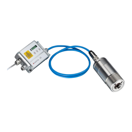
- Page 1 Operator’s Manual ® optris CTvideo 1M/ 2M/ 3M Infrared-thermometer 1.888.610.7664 www.calcert.com sales@calcert.com...
-
Page 2: Table Of Contents
Table of Contents Table of Contents Table of Contents ............................. 3 General Information ..........................8 Description ............................8 Warranty ............................9 Scope of Supply ..........................10 Maintenance ........................... 10 Model Overview ..........................11 Factory Default Settings ......................... 12 Technical Data ............................14 General Specifications ........................ - Page 3 Measurement Specifications [3M models] ..................18 Optical Charts ..........................19 Mechanical Installation .......................... 22 Accessories ............................25 Air Purge Collar ..........................25 Mounting Bracket ........................... 26 Water Cooled Housing ........................27 Rail Mount Adapter for Electronic box .................... 28 Electrical Installation ..........................29 Cable Connections .........................
- Page 4 Table of Contents 5.1.5 Cable Assembling ........................32 Ground Connection ........................33 Sensing head Calibration Code ..................... 34 Outputs and Inputs ..........................35 Analog Output ..........................35 Digital Interface ..........................36 Functional Inputs ..........................36 Alarms ............................37 6.4.1 Output channel 1 ........................37 6.4.2 Visual Alarms ..........................
- Page 5 Focusing and Video Sighting ......................46 Error messages ..........................47 IRmobile app ............................48 Software CompactConnect ........................50 Installation ............................50 Communication Settings ........................ 52 9.2.1 Serial Interface ........................... 52 9.2.2 Protocol ............................52 9.2.3 ASCII protocol ..........................52 9.2.4 Saving of parameter settings .....................
- Page 6 Table of Contents 11.3 Characteristic Emissivities......................56 Appendix A – Emissivity Table Metals ......................57 Appendix B – Emissivity Table Non Metals ....................59 Appendix C – Smart Averaging ........................60 Appendix D – Declaration of Conformity ..................... 61 1.888.610.7664 www.calcert.com sales@calcert.com...
-
Page 7: General Information
1.1 Description Thank you for choosing the optris® CTvideo infrared thermometer. The sensors of the optris CTvideo series are noncontact infrared temperature sensors. They calculate the surface temperature based on the emitted infrared energy of objects [►10 Basics of Infrared Thermometry]. The alignment of the sensor can be done with the integrated video sighting and crosshair laser aiming. -
Page 8: Warranty
General Information ► All accessories can be ordered according to the referred part numbers in brackets [ ]. 1.2 Warranty Each single product passes through a quality process. Nevertheless, if failures occur please contact the customer service at once. The warranty period covers 24 months starting on the delivery date. After the warranty is expired the manufacturer guarantees additional 6 months warranty for all repaired or substituted product components. -
Page 9: Scope Of Supply
1.3 Scope of Supply CTvideo sensing head with connection cable and electronic box Mounting nut and mounting bracket (fixed) 5 m USB cable Software CompactConnect Operators manual 1.4 Maintenance Lens cleaning: Blow off loose particles using clean compressed air. The lens surface can be cleaned with a soft, humid tissue (moistened with water) or a lens cleaner (e.g. -
Page 10: Model Overview
General Information 1.5 Model Overview The sensors of the CTvideo series are available in the following basic versions: Model Model code Measurement Spectral Typical applications range response 485 to 1050 °C CT video 1M 650 to 1800 °C 1,0 µm Metals and ceramic surfaces 1MH1 800 to 2200 °C... -
Page 11: Factory Default Settings
1.6 Factory Default Settings The unit has the following presetting at time of delivery: Signal output object temperature 0-5 V Emissivity 1,000 Transmissivity 1,000 Average time (AVG) inactive Smart Averaging active Peak hold inactive Valley hold inactive 1MH1 2MH1 3MH1 Lower limit temperature range [°C] Upper limit temperature range [°C] 1050... - Page 12 General Information 3MH2 3MH3 Lower limit temperature range [°C] Upper limit temperature range [°C] 1500 1800 Lower alarm limit [°C] (normally closed) Upper alarm limit [°C] 1000 1200 normally open Lower limit signal output Upper limit signal output Temperature unit °C Ambient temperature compensation internal head temperature probe...
-
Page 13: Technical Data
2 Technical Data 2.1 General Specifications Sensing head Electronic box Environmental rating IP65 (NEMA-4) Ambient temperature -20...70 °C -20...85 °C Storage temperature -40...85 °C Relative humidity 10...95 %, non condensing Material stainless steel die casting zinc Dimensions 116 mm x 50 mm, M48x1,5 89 mm x 70 mm x 30 mm Weight 600 g... -
Page 14: Electrical Specifications
Technical Data 2.2 Electrical Specifications Power Supply 8–36 VDC Current draw max. 160 mA Aiming laser 635 nm, 1 mW, On/ Off via programming keys or software Video sighting Digital (USB 2.0), 640 x 480 px, FOV 3.1° x 2.4° Output/ analog selectable: 0/ 4–20 mA, 0–5/ 10 V, thermocouple (J or K) or alarm output (Signal source: object temperature) -
Page 15: Measurement Specifications [1M Models]
2.3 Measurement Specifications [1M models] 1MH1 650…1800 °C Temperature range (scalable) 485...1050 °C 800...2200 °C Spectral range 1,0 µm Optical resolution 150:1 300:1 1), 2), 3) System accuracy ±(0,3 % of reading +2 °C) 1), 3) Repeatability ±(0,1 % of reading +1 °C) Temperature resolution (NETD) 0,1 K Exposure time (90% signal) -
Page 16: Measurement Specifications [2M Models]
Technical Data 2.4 Measurement Specifications [2M models] 2MH1 385…1600 °C Temperature range (scalable) 250...800 °C 490...2000 °C Spectral range 1,6 µm Optical resolution 150:1 300:1 1), 2), 3) System accuracy ±(0,3 % of reading +2 °C) 1), 3) Repeatability ±(0,1 % of reading +1 °C) Temperature resolution (NETD) 0,1 K Exposure time (90% signal) -
Page 17: Measurement Specifications [3M Models]
2.5 Measurement Specifications [3M models] 3MH1 3MH2 3MH3 100…600 °C 200…1500 °C 250…1800 °C Temperature range (scalable) 50...400 °C 150...1000 °C Spectral range 2,3 µm Optical resolution 60:1 100:1 300:1 2), 3), 4) System accuracy ±(0,3 % of reading +2 °C) 2), 4) Repeatability ±(0,1 % of reading +1 °C) -
Page 18: Optical Charts
As an alternative to the optical diagrams, the spot size calculator can also be used on the Optris website or via the Optris calculator app. The app can be downloaded for free from the Google Play Store (see QR code). - Page 19 D = Distance from front of the sensing head to the object S = Spot size 3ML: SF optics (D:S=60:1) spot size 11,7 18,3 26,7 41,7 83,3 measurement distance 1100 1600 2500 5000 3ML: CF optics (D:S=60:1) spot size measurement distance 3MH: SF optics (D:S=100:1) spot size 11,0...
- Page 20 Technical Data 1ML/2ML: SF optics (D:S=150:1) spot size 10,7 16,7 33,3 measurement distance 1100 1600 2500 5000 1ML/2ML: CF optics (D:S=150:1) spot size measurement distance 1MH-H1/2MH-H1/3MH1-H3: SF optics (D:S=300:1) spot size 16,7 measurement distance 1100 1600 2500 5000 1MH-H1/2MH-H1/3MH1-H3: CF optics (D:S=300:1) spot size measurement distance 1.888.610.7664...
-
Page 21: Mechanical Installation
3 Mechanical Installation The CTvideo is equipped with a metric M48x1,5 thread and can be installed either directly via the sensor thread or with help of the supplied mounting nut (standard) and fixed mounting bracket (standard) to a mounting device available. CTvideo sensing head (Basic version) Make sure to keep the optical path clear of any obstacles. - Page 22 Mechanical Installation CTvideo sensing head (High temperature version) 1.888.610.7664 www.calcert.com sales@calcert.com...
- Page 23 Electronic box For an exact alignment of the head to the object please activate the integrated video and/ or crosshair laser sighting. [►7 Operating, 7.2 Sighting] Mounting bracket, adjustable in one axis [ACCTLFB] – standard scope of supply 1.888.610.7664 www.calcert.com sales@calcert.com...
-
Page 24: Accessories
Accessories 4 Accessories 4.1 Air Purge Collar The lens must be kept clean at all times from dust, smoke, fumes and other contaminants in order to avoid reading errors. These effects can be reduced by using an air purge collar. Make sure to use oil-free, technically clean air, only. -
Page 25: Mounting Bracket
4.2 Mounting Bracket Mounting bracket, adjustable in two axes [ACCTLAB] This adjustable mounting bracket allows an adjustment of the sensor in two axis. 1.888.610.7664 www.calcert.com sales@calcert.com... -
Page 26: Water Cooled Housing
Accessories 4.3 Water Cooled Housing To avoid condensation on the optics an air purge collar is recommended. Water flow rate: approx. 2 l/ min (Cooling water temperature should not exceed 30 °C) Water cooled housing [ACCTLW] Hose connection: 6x8 mm Thread (fitting): G 1/8 inch The sensing head can be used at ambient temperatures up to 70 °C without cooling. -
Page 27: Rail Mount Adapter For Electronic Box
4.4 Rail Mount Adapter for Electronic box With the rail mount adapter the CTvideo electronics can be mounted easily on a DIN rail (TS35) according EN50022. Rail mount adapter [ACCTRAIL] ► All accessories can be ordered according to the referred part numbers in brackets [ ]. 1.888.610.7664 www.calcert.com sales@calcert.com... -
Page 28: Electrical Installation
Electrical Installation 5 Electrical Installation 5.1 Cable Connections The CTvideo sensing heads are equipped with connectors in the backplane. Therefore an opening of the sensing head for assembling or disassembling is not necessary. An USB cable (5 m) is already connected on the electronics and can be used for linking to a computer. - Page 29 CTvideo Basic version CTvideo High temperature version 1.888.610.7664 www.calcert.com sales@calcert.com...
-
Page 30: Designation
Electrical Installation 5.1.3 Designation +8..36 VDC Power supply Ground (0 V) of power supply Ground (0 V) of internal in- and outputs Alarm 2 (Open collector output) OUT-TC Analog output thermocouple (J or K) OUT-mV/mA Analog output object temperature (mV or mA) F1-F3 Functional inputs Ground (0 V) -
Page 31: Cable Assembling
5.1.5 Cable Assembling The cable gland M12x1,5 allows the use of cables with a diameter of 3 to 5 mm. Remove the isolation from the cable (40 mm power supply, 50 mm signal outputs, 60 mm functional inputs). Cut the shield down to approximately 5 mm and spread the strands out. Extract about 4 mm of the wire isolation and tin the wire ends. -
Page 32: Ground Connection
Electrical Installation 5.2 Ground Connection At the bottom side of the mainboard PCB you will find a connector (jumper) which has been placed from factory side as shown in the picture [bottom and middle pin connected]. In this position the ground connections (GND power supply/ outputs) are connected with the ground of the electronics housing. -
Page 33: Sensing Head Calibration Code
5.3 Sensing head Calibration Code Every head has a specific calibration code, which is printed on the head. For a correct temperature measurement and functionality of the sensor this calibration code must be stored into the electronic box. The calibration code consists of five blocks with 4 characters each. –... -
Page 34: Outputs And Inputs
Outputs and Inputs 6 Outputs and Inputs 6.1 Analog Output This output is used for the object temperature. The selection of the output signal can be done via the programming keys [►7 Operating]. The CompactConnect software allows the programming of output channel 1 as an alarm output. -
Page 35: Digital Interface
6.2 Digital Interface The CTvideo sensors are equipped with an USB interface. The interface board is located beside the LCD display. To uninstall the board please disconnect both of the M3x5 screws. Please pay attention to the correct positioning of the pin strip if you install the board. -
Page 36: Alarms
Outputs and Inputs 6.4 Alarms The CTvideo has the following Alarm features: All alarms (alarm 1, alarm 2, output channel 1 and 2 if used as alarm output) have a fixed hysterese of 2 K. 6.4.1 Output channel 1 To activate the alarm function the output channel has to be switched into digital mode. For this purpose the software CompactConnect is required. -
Page 37: Open Collector Output / Al2
6.4.3 Open collector output / AL2 The transistor acts as a switch. In case of alarm, the contact is closed. A load/consumer (Relay, LED or a resistor) must always be connected. The alarm voltage (here 24V) must not be connected directly to the alarm output (short circuit). -
Page 38: Operating
Operating 7 Operating After power up the unit the sensor starts an initializing routine for some seconds. During this time the display will show INIT. After this procedure the object temperature is shown in the display. The display backlight color changes according to the alarm settings [►6.4 Alarms]. 7.1 Sensor Setup The programming keys Mode, Up and Down enable the user to set the sensor on-site. - Page 39 Display Mode [Sample] Adjustment Range 142.3C Object temperature (after signal processing) [142,3 °C] fixed S ON ON/ OFF Laser Sighting [On] 127CH Head temperature [127 °C] fixed 25CB Box temperature [25 °C] fixed 142CA Current object temperature [142 °C] fixed ð...
- Page 40 Operating ð MV5 Selection of the Output signal. By pressing Up or Down the different output signals can be selected (see table). S ON Activating (ON) and Deactivating (OFF) of the Sighting Laser. By pressing Up or Down the laser can be switched on and off. E0.970 Setup of Emissivity.
- Page 41 of the algorithm is according to the peak hold algorithm (inverted). If the value is set to 0.0 the display will show --- (function deactivated). Signal graph with P---- ▬ TProcess with Peak Hold (Hold time = 1s) ▬ TActual without post processing 1.888.610.7664 www.calcert.com sales@calcert.com...
- Page 42 Operating Setup of the Lower limit of temperature range. The minimum difference between lower and upper limit is 20 K. If you set the lower limit to a value ≥ upper limit the upper limit will be adjusted to [lower limit + 20 K] automatically. n 500.0 Setup of the Upper limit of the temperature range.
- Page 43 Especially if there is a big difference between the ambient temperature at the object and the head temperature the use of Ambient temperature compensation is recommended. B 9.6 Setup of the Baud rate for digital data transfer. 1.888.610.7664 www.calcert.com sales@calcert.com...
-
Page 44: Sighting
Operating 7.2 Sighting The CTvideo has an integrated video camera which is using the same optical channel than the IR detector. In addition the sensor has a cross laser aiming which marks the center of the measurement spot at any distance. The combination of video and laser sighting enables a perfect alignment of the sensor to the object. -
Page 45: Focusing And Video Sighting
7.3 Focusing and Video Sighting On the back plane of the sensor you will find a rotary button for focusing of the optics. To set the focus to the desired measurement distance you have to connect the sensor with a PC using the USB cable. Please start the CompactConnect software. -
Page 46: Error Messages
Operating 7.4 Error messages The display of the sensor can show the following error messages: 1. Digit: No error Head temperature probe short circuit to GND Box temperature too low Box temperature too high Box temperature probe disconnected Box temperature probe short circuit to GND 2. -
Page 47: Irmobile App
8 IRmobile app The CTvideo sensor has a direct connection to an Android smartphone or tablet. All you have to do is download the IRmobile app for free in the Google Play store. This can also be done via the QR code. With IRmobile you are able to monitor and analyse your infrared temperature measurement on a connected smartphone or tablet. - Page 48 Integrated simulator Supported for: Optris pyrometers: Compact series, high performance series and video thermometers Optris IR cameras: PI and Xi series For android devices running 5.0 or higher with a micro USB or USB-C port supporting USB-OTG (On The Go) 1.888.610.7664...
-
Page 49: Software Compactconnect
ROM. Follow the instructions of the wizard until the CD-ROM drive installation is finished. Alternatively, the software can also be downloaded via the Optris website under the following The installation wizard will place a launch icon on the desktop and in the start menu: [Start]\Programs\CompactConnect. - Page 50 Software CompactConnect Main Features: Alignment of the sensor Graphic display temperature trends automatic data logging video snapshot generation for analysis and documentation Complete sensor setup and remote controlling Adjustment of signal processing functions Programming of outputs and functional inputs 1.888.610.7664 www.calcert.com sales@calcert.com...
-
Page 51: Communication Settings
9.2 Communication Settings 9.2.1 Serial Interface Baud rate: 9,6...115,2 kBaud (adjustable on the unit or via software) Data bits: Parity: none Stop bits: Flow control: 9.2.2 Protocol All sensors of the CTvideo series are using a binary protocol. Alternatively they can be switched to an ASCII protocol. -
Page 52: Saving Of Parameter Settings
Software CompactConnect 9.2.4 Saving of parameter settings After power on of the CTvideo sensor the flash mode is active. It means, changed parameter settings will be saved in the internal Flash-EEPROM and will be kept also after the sensor is switched off. In case settings should be changed quite often or continuously the flash mode can be switched off by using the following command: Decimal:... -
Page 53: Basics Of Infrared Thermometry
10 Basics of Infrared Thermometry Depending on the temperature each object emits a certain amount of infrared radiation. A change in the temperature of the object is accompanied by a change in the intensity of the radiation. For the measurement of “thermal radiation”... -
Page 54: Emissivity
Emissivity 11 Emissivity 11.1 Definition The intensity of infrared radiation, which is emitted by each body, depends on the temperature as well as on the radiation features of the surface material of the measuring object. The emissivity (ε – Epsilon) is used as a material constant factor to describe the ability of the body to emit infrared energy. -
Page 55: Characteristic Emissivities
and take the temperature of the sticker. Afterwards, determine the temperature of the adjacent area on the measuring object and adjust the emissivity according to the value of the temperature of the sticker. ► Cove a part of the surface of the measuring object with a black, flat paint with an emissivity of 0,98. Adjust the emissivity of your infrared thermometer to 0,98 and take the temperature of the colored surface. -
Page 56: Appendix A - Emissivity Table Metals
Appendix A – Emissivity Table Metals Appendix A – Emissivity Table Metals Material typical Emissivity Spectral response 1,0 µm 1,6 µm 5,1 µm 8-14 µm Aluminium non oxidized 0,1-0,2 0,02-0,2 0,02-0,2 0,02-0,1 polished 0,1-0,2 0,02-0,1 0,02-0,1 0,02-0,1 roughened 0,2-0,8 0,2-0,6 0,1-0,4 0,1-0,3 oxidized... - Page 57 Material typical Emissivity Spectral response 1,0 µm 1,6 µm 5,1 µm 8-14 µm Lead polished 0,35 0,05-0,2 0,05-0,2 0,05-0,1 roughened 0,65 oxidized 0,3-0,7 0,2-0,7 0,2-0,6 Magnesium 0,3-0,8 0,05-0,3 0,03-0,15 0,02-0,1 Mercury 0,05-0,15 0,05-0,15 0,05-0,15 Molybdenum non oxidized 0,25-0,35 0,1-0,3 0,1-0,15 oxidized 0,5-0,9 0,4-0,9...
-
Page 58: Appendix B - Emissivity Table Non Metals
Appendix B – Emissivity Table Non Metals Appendix B – Emissivity Table Non Metals Material typical Emissivity Spectral response 1,0 µm 2,2 µm 5,1 µm 8-14 µm Asbestos 0,95 Asphalt 0,95 0,95 Basalt Carbon non oxidized 0,8-0,9 0,8-0,9 0,8-0,9 graphite 0,8-0,9 0,7-0,9 0,7-0,8... -
Page 59: Appendix C - Smart Averaging
Appendix C – Smart Averaging The average function is generally used to smoothen the output signal. With the adjustable parameter time this function can be optimal adjusted to the respective application. One disadvantage of the average function is that fast temperature peaks which are caused by dynamic events are subjected to the same averaging time. -
Page 60: Appendix D - Declaration Of Conformity
Appendix D – Declaration of Conformity Appendix D – Declaration of Conformity 1.888.610.7664 www.calcert.com sales@calcert.com...
Need help?
Do you have a question about the CTvideo 1M and is the answer not in the manual?
Questions and answers