Table of Contents
Advertisement
Quick Links
Advertisement
Table of Contents

Related Manuals for optris CTratio


Summary of Contents for optris CTratio
- Page 1 ® optris CTratio ¯¯¯¯¯¯¯¯¯¯¯¯¯¯¯¯¯¯¯¯¯¯¯¯¯¯¯¯¯¯¯¯¯¯¯¯¯¯¯¯¯¯¯¯¯¯¯¯¯¯¯¯¯¯¯¯¯¯¯¯¯¯¯¯¯¯¯¯¯¯¯¯¯¯¯¯¯¯¯¯¯¯¯¯¯¯¯¯¯¯¯¯¯¯¯¯¯¯¯¯¯¯¯¯¯¯¯¯¯¯¯¯¯¯¯¯¯¯¯¯¯¯¯¯¯¯¯¯¯¯¯¯¯¯¯¯¯¯¯¯¯¯¯¯¯¯¯¯¯¯¯¯¯¯¯¯¯¯¯¯¯¯¯¯¯¯¯¯¯¯¯¯¯¯¯¯¯¯¯¯¯¯¯¯¯¯¯¯¯¯¯¯¯¯¯¯¯¯¯¯¯¯¯¯¯¯¯¯¯¯¯¯¯¯¯¯¯¯¯¯ Fiber Optics Ratio Thermometer Operators manual...
- Page 3 The manufacturer reserves the right to exchange components of the product instead of repairing it. If the failure results from misuse or neglect the user has to pay for the repair. In that case you may ask for a cost estimate beforehand. optris CTratio – E2013-04-A...
-
Page 4: Table Of Contents
Appendix A – Emissivity Table Metals Electrical Installation Appendix B – Emissivity Table Non Metals Cable Connections Appendix C – Smart Averaging Ground Connection Outputs and Inputs Analog Output Digital I/O pins Programming Interface Relay Outputs Alarms optris CTratio – E2013-04-A... -
Page 5: Description
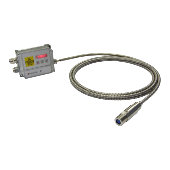
1-color-mode as well as in the ratio- or 2-color-mode [► Basics of Infrared Thermometry]. The optical sensing head of the CTratio is made of stainless steel (IP65/ NEMA-4 rating) and is connected via a rugged fiber optics, which is protected by a stainless steel armour, with the sensor electronics (die casting zinc box). -
Page 6: Scope Of Supply
The CTratio sensing head is a sensitive optical system. Please use only the thread for mechanical installation. Avoid mechanical violence on the head – this may destroy the system (expiry of warranty). Scope of Supply CTratio sensing head with fibre connection cable and electronic box ... -
Page 7: Safety Note
Cautions Avoid static electricity. The fiber optical cable has a minimum bending radius of 40 mm. In case of problems or questions which may arise when you use the CTratio, please contact our service department. Read the manual carefully before the initial start-up. The producer reserves the right to change the herein described specifications in case of technical advance of the product. -
Page 8: Factory Default Settings
Output channel 1 T 2C (2C temperature) Lower limit temperature range [°C] Upper limit temperature range [°C] 1800 Lower limit signal output Upper limit signal output Max. attenuation 95 % Temperature unit °C Baud rate [kBaud] optris CTratio – E2013-04-A... -
Page 9: Technical Data
Fiber optics length 3 m (standard), 6 m, 10 m, 15 m, 22 m IEC 68-2-6: 3G, 11 – 200Hz, any axis Vibration Shock IEC 68-2-27: 50G, 11ms, any axis Software CompactConnect (optional; for programming only) optris CTratio – E2013-04-A... -
Page 10: Electrical Specifications
500 Ω (at 8-36 VDC) min. 100 KΩ load impedance Digital interface USB (optional; for programming only) Relay outputs 2 x 60 VDC/ 42 VAC , 0,4 A; optically isolated (optional plug-in module) optris CTratio – E2013-04-A... -
Page 11: Measurement Specifications
One-color-, Two-color-mode, Attenuation monitoring, Alarm, Average, Peak hold, Valley hold, Advanced peak hold with threshold and hysteresis (adjustable via programming keys or software) at ambient temperature 235 °C = 1/ Response time 1s with dynamic adaptation at low signal levels optris CTratio – E2013-04-A... -
Page 12: Optics
Optics The CTratio is available in two focus versions: SF optics: 41 mm@ 1524 mm (D:S = 40:1) CF2 optics: 7,7 mm@ 305 mm (D:S = 40:1) The following optical charts show the diameter of the measuring spot in dependence on the distance between measuring object and sensing head. - Page 13 CF2 optics distance = distance from front edge of the sensing head to the measurement object The D:S ratio is valid for the focus point. optris CTratio – E2013-04-A...
- Page 14 Measurement of objects smaller than the measurement spot Measurement through a dirty lens or dirty sighting window [► The Ratio Principle] Please note that the sensor accuracy is not guaranteed for signal reductions of more than 95%. optris CTratio – E2013-04-A...
-
Page 15: Mechanical Installation
Mechanical Installation The CTratio sensing heads are equipped with a metrical M18x1-thread and can be installed either directly via the sensor thread or with help of the hex nuts (2 pieces included in scope of supply) to the mounting bracket available. - Page 16 Electronic box The electronic box is also available with closed cover (display and programming keys with no access from outside) [ACCTCOV]. optris CTratio – E2013-04-A...
-
Page 17: Accessories
(in the 1-color-mode). These effects can be reduced by using an air purge collar. Make sure to use oil-free, technically clean air, only. The needed amount of air (approx. 2...10 l/ min.) depends on the application and the installation conditions on-site. optris CTratio – E2013-04-A... - Page 18 Rail Mount Adapter for Electronic box With the rail mount adapter the CTratio electronics can be mounted easily on a DIN rail (TS35) according EN50022. ACCTRAIL optris CTratio – E2013-04-A...
-
Page 19: Laser Sighting
USB interface! SAFETY SWITCH: If the fiber optical cable will be removed from the electronics the laser will be switched off automatically. Any manipulation at this safety switch is prohibited. optris CTratio – E2013-04-A... -
Page 20: Electrical Installation
Electrical Installation Cable Connections For the electrical installation of the CTratio please open at first the cover of the electronic box (4 screws). Below the display are the screw terminals for the cable connection. Designation +8..36VDC Power supply Ground (0V) of power supply... - Page 21 Screw the cap tight. Every single wire may be connected to the according screw clamps according to their colors. Use shielded cables only. The sensor shield has to be grounded. optris CTratio – E2013-04-A...
-
Page 22: Ground Connection
On the mainboard PCB you will find a black wire which is connecting factory-default the ground connections (GND power supply/ outputs) with the ground of the electronics housing. To avoid ground loops and related signal interferences in industrial environments it might be necessary to interrupt this connection. optris CTratio – E2013-04-A... -
Page 23: Outputs And Inputs
Outputs and Inputs The CTratio has an analog output and two digital I/O pins (programmable as in- or output). Analog Output The selection of the signal on output channel 1 can be done via the programming keys [► Operating]. The following output signals can be selected:... -
Page 24: Digital I/O Pins
I/O pins The CTratio has two digital pins which can be programmed as outputs (digital) or as inputs (digital or analog) using the CompactConnect software. The following functions are available: Function I/O pin acts as Description Digital Alarm output digital Open collector output/ definition as HIGH- or LOW alarm via norm. -
Page 25: Programming Interface
Programming Interface CTratio sensors can be optionally equipped with an USB-interface for programming of the sensor. If you want to install the interface, plug the interface board into the place provided, which is located beside the display. In the correct position the holes of the interface match with the thread holes of the electronic box. -
Page 26: Relay Outputs
Relay Outputs The CTratio can be optionally equipped with a relay output. The relay board will be installed the same way as the programming interface. A simultaneous installation of the programming interface and the relay outputs is not possible. The relay board provides two fully isolated switches, which have the capability to switch max. -
Page 27: Alarms
Alarms The CTratio has the following Alarm features: All alarms have a fixed hysteresis of 2 K. Visual Alarms These alarms will cause a change of the color of the LCD display and will also change the status of the optional relays interface. -
Page 28: Operating
The signal processing features Peak hold and Valley hold cannot be selected simultaneously. Factory Default Setting To set the CTratio back to the factory default settings, please press at first the Down-key and then the Mode-key and keep both pressed for approx. 3 seconds. - Page 29 °C Temperature unit [°C] °C/ °F 01 … 32 Multidrop adress [1] (only with RS485 interface) Baud rate in kBaud [115] 9,6/ 19,2/ 38,4/ 57,6/ 115,2 kBaud optris CTratio – E2013-04-A...
- Page 30 Setup of Average time. If the value is set to 0.0 the display will show --- (function deactivated). In this mode an arithmetic algorithm will be performed to smoothen the signal. The set time is the time constant. This function can be combined with all other post processing functions. optris CTratio – E2013-04-A...
- Page 31 Setup of the Upper limit of the signal output. This setting allows an assignment of a certain signal output level to the upper limit of the temperature range. The adjustment range corresponds to the selected output mode (e.g. 0-5 V). optris CTratio – E2013-04-A...
- Page 32 Signal graph with P---- ▬ TProcess with Peak Hold (Hold time = 1s) ▬ TActual without post processing optris CTratio – E2013-04-A...
- Page 33 Setup of the Multidrop address. In a RS485 network each sensor will need a specific address. This menu item will only be shown if a RS485 interface board is plugged in. B 115k Setup of the Baud rate for digital data transfer. optris CTratio – E2013-04-A...
-
Page 34: Software Compactconnect
If you want to uninstall the software from your system please use the uninstall icon in the start menu. You will find a detailed software manual on the CD. Main Features: Complete sensor setup Adjustment of signal processing functions Programming of outputs and functional inputs optris CTratio – E2013-04-A... -
Page 35: Communication Settings
Communication Settings Serial Interface Baud rate: 9,6...115,2 kBaud (adjustable on the unit or via software) Data bits: Parity: none Stop bits: Flow control: Protocol All sensors of the CTratio series are using a binary protocol. optris CTratio – E2013-04-A... -
Page 36: Basics Of Infrared Thermometry
Distance to Spot size. The spectral filter selects the wavelength range, which is relevant for the temperature measurement. The detector in cooperation with the processing electronics transforms the emitted infrared radiation into electrical signals. optris CTratio – E2013-04-A... -
Page 37: The Ratio Principle
Sighting paths are partially blocked (either intermittently or permanently). ► Dirt, smoke, or steam is in the atmosphere between the sensor and target. ► Measurements are made through items or areas that reduce emitted energy, such as grills, screens, channels or small openings optris CTratio – E2013-04-A... - Page 38 (emissivity = 1.0) or greybody (emissivity < 1.0 but constant), then their ratio would be 1, and target emissivity would not be an influence. However, in nature there is no such thing as a greybody. The emissivity of all real objects changes with wavelength and temperature, at varying degrees, depending on the material. optris CTratio – E2013-04-A...
- Page 39 To determine how to use 2-color sensors with your application when uncertain or changing emissivities are a factor, please contact your sales representative. optris CTratio – E2013-04-A...
-
Page 40: Emissivity
ACLSED) onto the measuring object, which covers it completely. Now set the emissivity to 0,95 and take the temperature of the sticker. Afterwards, determine the temperature of the adjacent area on the measuring object and adjust the emissivity according to the value of the temperature of the sticker. optris CTratio – E2013-04-A... -
Page 41: Characteristic Emissivities
temperature measuring angle geometry of the surface thickness of the material constitution of the surface (polished, oxidized, rough, sandblast) spectral range of the measurement transmissivity (e.g. with thin films) optris CTratio – E2013-04-A... -
Page 42: Characteristic Slope Values
Attenuation The CTratio is able to measure the temperature of targets smaller than the field of view (FOV). If the target size is smaller than the FOV (and thus attenuating the signal) this may cause a small inaccuracy of the reading. - Page 43 This figure is showing the typical temperature reading of a ratio thermometer optris CT ratio in both the 1- color- and the 2-color-mode in addiction of increasing contamination of the optical transmission path in- between the target and the ratio thermometer. Due to the ratio principle the 2 channel signal (upper curve) stays very stable over a wide range of attenuation up to over 90%.
-
Page 44: Appendix A - Emissivity Table Metals
0,4-0,9 0,6-0,9 0,6-0,9 0,7-0,95 Iron non oxidized 0,35 0,1-0,3 0,05-0,25 0,05-0,2 rusted 0,6-0,9 0,5-0,8 0,5-0,7 oxidized 0,7-0,9 0,5-0,9 0,6-0,9 0,5-0,9 forged, blunt molten 0,35 0,4-0,6 Iron, casted non oxidized 0,35 0,25 oxidized 0,7-0,9 0,65-0,95 0,6-0,95 optris CTratio – E2013-04-A... - Page 45 0,8-0,9 0,7-0,9 oxidized 0,8-0,9 0,8-0,9 0,7-0,9 0,7-0,9 non oxidized 0,25 0,1-0,3 0,05 0,05 Titanium polished 0,5-0,75 0,3-0,5 0,1-0,3 0,05-0,2 oxidized 0,6-0,8 0,5-0,7 0,5-0,6 Wolfram polished 0,35-0,4 0,1-0,3 0,05-0,25 0,03-0,1 Zinc polished 0,05 0,03 0,02 oxidized 0,15 optris CTratio – E2013-04-A...
-
Page 46: Appendix B - Emissivity Table Non Metals
0,8-0,95 0,98 Limestone 0,4-0,98 0,98 Paint non alkaline 0,9-0,95 Paper any color 0,95 0,95 Plastic >50 µm non transparent 0,95 0,95 Rubber 0,95 Sand Snow Soil 0,9-0,98 Textiles 0,95 0,95 Water 0,93 Wood natural 0,9-0,95 0,9-0,95 optris CTratio – E2013-04-A... -
Page 47: Appendix C - Smart Averaging
Therefore those peaks can only be seen with a delay on the signal output. The function Smart Averaging eliminates this disadvantage by passing those fast events without averaging directly through to the signal output. Signal graph with Smart Averaging function Signal graph without Smart Averaging function optris CTratio – E2013-04-A...
Need help?
Do you have a question about the CTratio and is the answer not in the manual?
Questions and answers