Table of Contents
Advertisement
Quick Links
Advertisement
Table of Contents

Subscribe to Our Youtube Channel
Related Manuals for optris CX


Summary of Contents for optris CX
- Page 1 Operator’s Manual ® optris Infrared thermometer...
- Page 2 Optris GmbH Ferdinand-Buisson-Str. 14 13127 Berlin Germany Tel.: +49 30 500 197-0 Fax: +49 30 500 197-10 E-mail: info@optris.global Internet: www.optris.global...
-
Page 3: Table Of Contents
Table of contents Table of contents Table of contents .............................. 3 General notes ............................6 Intended use ............................6 Warranty ............................. 7 Scope of delivery ..........................7 Maintenance ............................8 Product overview ..........................8 Factory Default Settings ........................9 Technical Data ............................10 Default settings .......................... - Page 4 Measurement specifications ......................13 Optical charts ............................ 14 CF-optics and protective window ...................... 16 Installation ............................... 17 Mechanical Installation ........................17 Electrical Installation ......................... 20 Software CompactConnect ........................24 Installation ............................24 Digital command set ..........................26 Basics of Infrared Thermometry ......................27 Emissivity ..............................
- Page 5 Table of contents Appendix A – Table of emissivity for metals ....................31 Appendix B - Table of emissivity for non-metals ..................32 Appendix C – Direct connection to a RS232 interface ................33 Appendix D - Smart Averaging ........................34 Appendix E –...
-
Page 6: General Notes
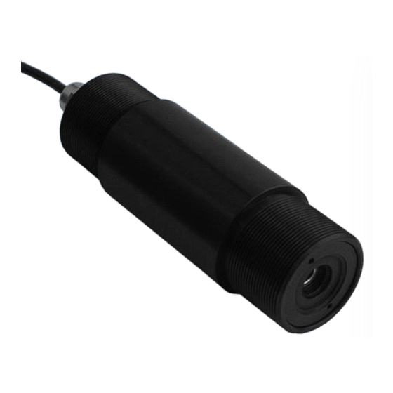
The sensors of the optris CX series are non-contact infrared temperature sensors. They calculate the surface temperature based on the emitted infrared energy of objects [►6 Basics of Infrared Thermometry]. The CX sensing head is a sensitive optical system. Please use only the thread for mechanical installation. ... -
Page 7: Warranty
If the failure results from misuse or neglect the user has to pay for the repair. In that case you may ask for a cost estimate beforehand. Scope of delivery CX incl. connection cable, mounting nut and operators manual... -
Page 8: Maintenance
Never use cleaning compounds which contain solvents (neither for the lens nor for the housing). 1.5 Product overview Model Model code Measurement Spectral Optic Specialty range response -30 to 900 °C 22:1 8-14 µm CX hs -20 to 150 °C 15:1 0,025 K resolution... -
Page 9: Factory Default Settings
General notes 1.6 Factory Default Settings At time of delivery the unit has the following pre-settings: CX hs -20…150 °C Temperature range: -18...500 °C 4…20 mA Output: Emissivity: 0,950 Transmissivity 1,000 Smart Averaging: active Ambient temperature source: Head temperature... -
Page 10: Technical Data
2 Technical Data 2.1 Default settings Smart Averaging means a dynamic average adaptation at high signal edges. [Activation via software only]. [► Appendix D - Smart Averaging If the unit is supplied together with the USB kit the output is already pre-set to digital communication (bidirectional). -
Page 11: General Specifications
Technical Data 2.2 General specifications CX hs Environmental rating: IP65 (NEMA-4) Ambient temperature: -20...75 °C Storage temperature: -40...85 °C Relative humidity: 10...95 %, non-condensing Material aluminum, black anodized Dimensions: Diameter: 42 mm/ Length: 130 mm Weight: 350 g Cable length:... -
Page 12: Electrical Specifications
1000 Ω loop impedance Power supply: 5...30 VDC Inverted RS232 signal, TTL, 9.6 kBaud white Current loop (+) yellow TxD (5 V) green RxD (5 V)/ Open-collector output brown Current loop (-)/ Ground () black Shield Figure 1: Dimensions CX... -
Page 13: Measurement Specifications
Technical Data 2.4 Measurement specifications CX hs Temperature range IR: -30...900 °C (scalable via software) -20…150 °C scalable via software) Spectral range: 8...14 µm Optical resolution: 22:1 15:1 CF-lens (optional): 0,6 mm@ 10 mm 0,8 mm@ 10 mm Accuracy: ±1,4 °C or ±1,0 % ±1,0 °C or ±1,0 %... -
Page 14: Optical Charts
Consequently, the spot should at all times have at least the same size like the object or should be smaller than that. As an alternative to the optical diagrams, the spot size calculator can also be used on the optris website http://www.optris.com/spot-size-calculator. - Page 15 Technical Data Figure 2: Optical chart optris CX (22:1) Figure 3: Optical chart optris CX with CF-lens (0.6 mm@ 10 mm)
-
Page 16: Cf-Optics And Protective Window
2.6 CF-optics and protective window If the CF-lens is used, the transmission has to be set to 0.78. To change this value the optional USB-Kit (including software) is necessary. The assigned transmission (average value) is a characteristic value which may has a certain scattering. -
Page 17: Installation
3 Installation 3.1 Mechanical Installation The CX is equipped with a 20 UNF-2B thread and can be installed either directly via the sensor thread or with the help of the hex nut (standard) to the mounting bracket available. Figure 5: CX – Dimensions... - Page 18 Mounting bracket Figure 6: Mounting angle [Order No.: ACCXFB] and adjustment angle [Order No.: ACCXAB] for CX...
- Page 19 Installation Air purge collar Use oil-free, technically clean air only. The needed amount of air (approx. 2...10 l/ min.) depends on the application and the installation conditions on-site. The lens must be kept clean at all times from dust, smoke, fumes and other contaminants in order to avoid reading errors.
-
Page 20: Electrical Installation
3.2 Electrical Installation Analog device (mA-output) Use shielded cables only. The sensor shield has to be grounded. Use a separate, stabilized power supply unit with an output voltage in the range of 5–28 VDC which can supply 100 mA. The residual ripple should be max 200 mV. ... - Page 21 Installation Digital Communication For digital communication the optional USB programming kit is required. Figure 9: USB-Kit: USB programming adaptor incl. terminal block and software CD [Order No.: ACCSUSBK] Connecting of the sensor cable and the USB cable 1. Connect each wire of the USB adapter cable with the same colored wire of the sensor cable by using the terminal block.
- Page 22 Figure 10: Connecting of the sensor cable and USB cable The sensor is offering two ways of digital communication: bidirectional communication (sending and receiving data) unidirectional communication (burst mode – the sensor is sending data only) Figure 11: Device with digital pin...
- Page 23 Installation Analog + Digital The optris CX is able to work in the digital mode and simultaneously as analog device (4-20 mA). In this case the sensor will be powered by the USB interface (5 V). Figure 12: Simultaneous analog and digital application...
-
Page 24: Software Compactconnect
4 Software CompactConnect Minimum system requirements: Windows 7, 8, 10 USB interface Hard disc with at least 30 MByte of free space At least 128 MByte RAM CD-ROM drive A detailed description is provided in the software manual on the software CD. 4.1 Installation 1. - Page 25 Software CompactConnect The installation wizard will place a launch icon on the desktop and in the start menu: Start\Programs\CompactConnect To uninstall the software from your system use the uninstall icon in the start menu. Main functions: Graphic display for temperature trends and automatic data logging for analysis and documentation ...
-
Page 26: Digital Command Set
Digital command set Kommandoliste CS/ CSmicro/ CX DEZIMAL Binär / ASCII Kommando Daten Antwort Ergebnis Einheit 0x01 Binär LESEN Temp - Target keine byte1 byte2 = (byte1 x 256 + byte2 - 1000) / 10 °C 0x02 Binär LESEN Temp - Head... -
Page 27: Basics Of Infrared Thermometry
Basics of Infrared Thermometry Basics of Infrared Thermometry Depending on the temperature each object emits a certain amount of infrared radiation. A change in the temperature of the object is accompanied by a change in the intensity of the radiation. For the measurement of “thermal radiation”... -
Page 28: Emissivity
7 Emissivity 7.1 Definition The intensity of infrared radiation, which is emitted by each body, depends on the temperature as well as on the radiation features of the surface material of the measuring object. The emissivity (ε – Epsilon) is used as a material constant factor to describe the ability of the body to emit infrared energy. -
Page 29: Determination Of Unknown Emissivity
Emissivity 7.2 Determination of unknown emissivity ► First determine the actual temperature of the measuring object with a thermocouple or contact sensor. Second, measure the temperature with the infrared thermometer and modify the emissivity until the displayed result corresponds to the actual temperature. ►... -
Page 30: Characteristic Emissivity
7.3 Characteristic emissivity In case none of the methods mentioned above help to determine the emissivity you may use the emissivity table ►Appendix A – Table of emissivity for metals and Appendix B - Table of emissivity for non-metals. These are average values, only. The actual emissivity of a material depends on the following factors: ... -
Page 31: Appendix A - Table Of Emissivity For Metals
Appendix A – Table of emissivity for metals Appendix A – Table of emissivity for metals typical typical Material Material Emissivity Emissivity Aluminium non oxidized 0,02-0,1 Lead roughened polished 0,02-0,1 oxidized 0,2-0,6 roughened 0,1-0,3 Magnesium 0,02-0,1 oxidized 0,2-0,4 Mercury 0,05-0,15 Brass polished 0,01-0,05... -
Page 32: Appendix B - Table Of Emissivity For Non-Metals
Appendix B - Table of emissivity for non-metals Material typical Emissivity Spectral response 1,0 µm 2,2 µm 5,1 µm 8-14 µm Asbestos 0,95 Asphalt 0,95 0,95 Basalt Carbon non oxidized 0,8-0,9 0,8-0,9 0,8-0,9 graphite 0,8-0,9 0,7-0,9 0,7-0,8 Carborundum 0,95 Ceramic 0,8-0,95 0,8-0,95 0,95... -
Page 33: Appendix C - Direct Connection To A Rs232 Interface
For a bidirectional RS232 connection of the sensor we recommend the interface circuit from Maxim, e.g. MAX3381E. Model UART-Voltage (RxD) 3,3 V UART-Voltage (TxD) 2,5 V CX connections: TxD (yellow) an T1IN RxD (green) an R1OUT GND (brown) an GND PC connections: connect T1OUT with RxD (PC) -
Page 34: Appendix D - Smart Averaging
Appendix D - Smart Averaging The average function is generally used to smoothen the output signal. With the adjustable parameter time this function can be optimal adjusted to the respective application. One disadvantage of the average function is that fast temperature peaks which are caused by dynamic events are subjected to the same averaging time. -
Page 35: Appendix E - Declaration Of Conformity
Appendix E – Declaration of Conformity Appendix E – Declaration of Conformity...
Need help?
Do you have a question about the CX and is the answer not in the manual?
Questions and answers