
Related Manuals for optris CSlaser LT


Summary of Contents for optris CSlaser LT
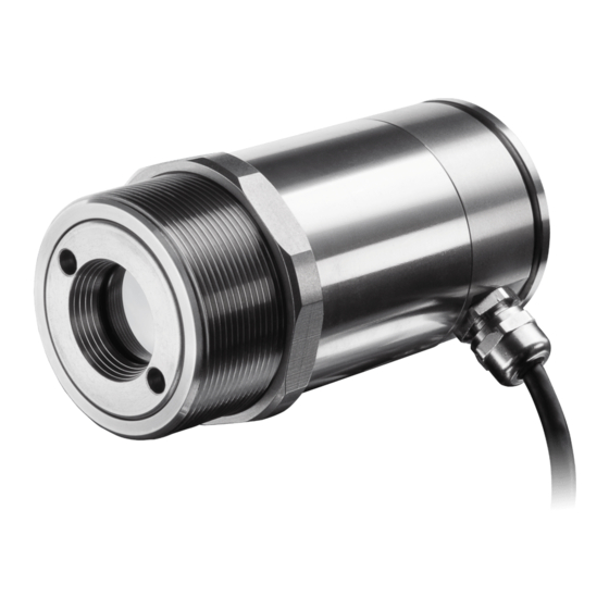
- Page 1 Operator‘s Manual optris ® CSlaser LT/ hs LT/ 2M/ G5 Infrared-thermometer 1.888.610.7664 www.calcert.com sales@calcert.com...
-
Page 2: Table Of Contents
Table of Contents Table of Contents Table of Contents ............................. 3 General Information ..........................7 Description ............................7 Warranty ............................8 Scope of Supply ..........................8 Maintenance ............................. 9 Model Overview ..........................9 Factory Default Settings ......................... 10 Technical Data ............................12 General Specifications ........................ - Page 3 Mechanical Installation .......................... 26 Accessories ............................27 Mounting Brackets .......................... 27 Air Purge Collar ..........................28 Water Cooled Housing ........................29 CoolingJacket Advanced ........................ 30 Outdoor protective housing ......................31 Electrical Installation ..........................32 Cable Connections ......................... 32 Analog Mode ..........................35 Digital Mode ...........................
- Page 4 Table of Contents Laser Sighting ............................39 IRmobile app ............................41 Software CompactConnect ........................43 Installation ............................43 Communication Settings ........................ 45 Digital Command Set ........................46 Basics of Infrared Thermometry......................47 Emissivity ............................... 48 11.1 Definition............................48 11.2 Determination of unknown Emissivities ..................48 11.3 Characteristic Emissivities......................
- Page 5 Appendix D - Declaration of Conformity ...................... 54 1.888.610.7664 www.calcert.com sales@calcert.com...
-
Page 6: General Information
1.1 Description Thank you for choosing the optris® CSlaser infrared thermometer. The sensors of the optris CSlaser series are noncontact infrared temperature sensors. They calculate the surface temperature based on the emitted infrared energy of objects [►10 Basics of Infrared Thermometry]. An integrated double laser aiming helps to mark the measurement spot on the object surface. -
Page 7: Warranty
1.2 Warranty Each single product passes through a quality process. Nevertheless, if failures occur please contact the customer service at once. The warranty period covers 24 months starting on the delivery date. After the warranty is expired the manufacturer guarantees additional 6 months warranty for all repaired or substituted product components. -
Page 8: Maintenance
General Information 1.4 Maintenance Lens cleaning: Blow off loose particles using clean compressed air. The lens surface can be cleaned with a soft, humid tissue (moistened with water) or a lens cleaner (e.g. Purosol or B+W Lens Cleaner). Never use cleaning compounds which contain solvents (neither for the lens nor for the housing). 1.5 Model Overview The sensors of the CSlaser series are available in the following basic versions: Spectral... -
Page 9: Factory Default Settings
1.6 Factory Default Settings The unit has the following presetting at time of delivery: Signal output object temperature 4-20 mA Emissivity (switches) 0,970 [LT, hs LT] 1,000 [2ML, 2MH, G5HF, G5H1F] Emissivity (via software) 1,000 Transmissivity 1,000 Average time (AVG) 0,2 s [LT, hs LT] 0,1 s [2ML, 2MH, G5HF, G5H1F] Smart Averaging... - Page 10 General Information Smart Averaging means a dynamic average adaptation at high signal edges. [Activation via software only]. ►Appendix C – Smart Averaging 1.888.610.7664 www.calcert.com sales@calcert.com...
-
Page 11: Technical Data
2 Technical Data 2.1 General Specifications Environmental rating IP65 (NEMA-4) Ambient temperature -20...85 °C Storage temperature -40...85 °C Relative humidity 10...95 %, non condensing Material stainless steel Dimensions 100 mm x 50 mm, M48x1,5 Weight 600 g Cable length 3 m, 8 m, 15 m (on connector version only) Cable diameter 5 mm... -
Page 12: Electrical Specifications
Technical Data 2.2 Electrical Specifications Power Supply 5–30 VDC Current draw (laser) 45 mA @ 5 V 20 mA @ 12 V 12 mA @ 24 V Aiming laser 635 nm, 1 mW, On/ Off via external switch (needs to be installed by user before start-up) or software Output/ analog 4–20 mA current loop... -
Page 13: Measurement Specifications
2.3 Measurement Specifications hs LT Temperature range (scalable) -30...1000 °C -20...150 °C Spectral range 8...14 µm Optical resolution 50:1 System accuracy 1), 2) ±1,0 °C or ±1,0 % Repeatability 1), 2) ±0,5 °C or ±0,5 % ±0,3 °C or ±0,3 % Thermal sensitivity (NETD) 0,1 K 0,025 K... - Page 14 Technical Data Temperature range (scalable) 250...800 °C 385...1600 °C Spectral range 1,6 µm Optical resolution 150:1 300:1 System accuracy ±(0,3 % of reading +2 °C) Repeatability ±(0,1 % of reading +1 °C) Thermal sensitivity (NETD) 0,1 K Emissivity/ Gain 0,100...1,100 (adjustable via switches on sensor or via software) IR window correction 0,100...1,100 (adjustable via software) Signal processing...
- Page 15 G5HF G5H1F Temperature range (scalable) 100...1200 °C 250...1650 °C 200…1450 °C 400…1650 °C Spectral range 5,0 µm Optical resolution 45:1 70:1 45:1 System accuracy 1), 2), 3) ±1,5 °C or ±1 % Repeatability 1), 2), 3) ±0,5 °C or ±0,5 % Thermal sensitivity (NETD) 0,1 K Response time (90% signal)
-
Page 16: Optical Charts
As an alternative to the optical diagrams, the spot size calculator can also be used on the Optris website or via the Optris calculator app. The app can be downloaded for free from the Google Play store (see QR code). - Page 17 Optics: SF D:S (focus distance) = 50:1/ 24mm@ 1200mm D:S (far field) = 20:1 Optics: CF1 D:S (focus distance) = 50:1/ 1,4mm@ 70mm D:S (far field) = 1,5:1 1.888.610.7664 www.calcert.com sales@calcert.com...
- Page 18 Technical Data Optics: CF2 D:S (focus distance) = 50:1/ 3mm@ 150mm D:S (far field) = 6:1 Optics: CF3 D:S (focus distance) = 50:1/ 4mm@ 200mm D:S (far field) = 8:1 1.888.610.7664 www.calcert.com sales@calcert.com...
- Page 19 Optics: CF4 D:S (focus distance) = 50:1/ 9mm@ 450mm D:S (far field) = 16:1 Optics: FF D:S (focus distance) = 300:1 12mm@ 3600mm D:S (far field) = 115:1 Optics: FF D:S (focus distance) = 150:1 24mm@ 3600mm D:S (far field) = 84:1 1.888.610.7664 www.calcert.com sales@calcert.com...
- Page 20 Technical Data Optics: SF D:S (focus distance) = 300:1 3,7mm@ 1100mm D:S (far field) = 48:1 Optics: SF D:S (focus distance) = 150:1 7,3mm@ 1100mm D:S (far field) = 42:1 Optics: CF2 D:S (focus distance) = 300:1 0,5mm@ 150mm D:S (far field) = 7,5:1 Optics: CF2 D:S (focus distance) = 150:1 1,0mm@ 150mm...
- Page 21 Optics: CF3 D:S (focus distance) = 300:1 0,7mm@ 200mm D:S (far field) = 10:1 Optics: CF3 D:S (focus distance) = 150:1 1,3mm@ 200mm D:S (far field) = 10:1 Optics: CF4 D:S (focus distance) = 300:1 1,5mm@ 450mm D:S (far field) = 22:1 Optics: CF4 D:S (focus distance) = 150:1 3,0mm@ 450mm...
- Page 22 Technical Data G5L/ G5HF/ G5H1F Optics: SF D:S (focus distance) = 45:1/ 27mm@1200mm D:S (far field) = 25:1 Optics: SF :S (focus distance) = 70:1/ 17mm@1200mm D:S (far field) = 33:1 G5L/ G5HF/ G5H1F Optics: CF1 D:S (focus distance) = 45:1/ 1,6mm@70mm D:S (far field) = 3:1 Optics: CF1 D:S (focus distance) = 70:1/ 1mm@70mm...
- Page 23 G5L/ G5HF/ G5H1F Optics: CF2 D:S (focus distance) = 45:1/ 3,4mm@150mm D:S (far field) = 6:1 Optics: CF2 D:S (focus distance) = 70:1/ 2,2mm@150mm D:S (far field) = 6,8:1 G5L/ G5HF/ G5H1F Optics: CF3 D:S (focus distance) = 45:1/ 4,5mm@200mm D:S (far field) = 8:1 Optics: CF3 D:S (focus distance) = 70:1/ 2,9mm@200mm...
- Page 24 Technical Data G5L/ G5HF/ G5H1F Optics: CF4 D:S (focus distance) = 45:1/ 10mm@450mm D:S (far field) = 15:1 Optics: CF4 D:S (focus distance) = 70:1/ 6,5mm@450mm D:S (far field) = 17,7:1 1.888.610.7664 www.calcert.com sales@calcert.com...
-
Page 25: Mechanical Installation
3 Mechanical Installation The CSlaser is equipped with a metric M48x1,5 thread and can be installed either directly via the sensor thread or with help of the supplied mounting nut (standard) and fixed mounting bracket (standard) to a mounting device available. CSlaser sensing head Make sure to keep the optical path clear of any obstacles. -
Page 26: Accessories
Accessories 4 Accessories 4.1 Mounting Brackets Mounting bracket, adjustable in two axes [ACCTLAB] For an exact sensor alignment to the object please activate the integrated double laser. [►7 Laser Sighting] Mounting bracket, adjustable in one axis [ACCTLFB] 1.888.610.7664 www.calcert.com sales@calcert.com... -
Page 27: Air Purge Collar
4.2 Air Purge Collar The lens must be kept clean at all times from dust, smoke, fumes and other contaminants in order to avoid reading errors. These effects can be reduced by using an air purge collar. Make sure to use oil-free, technically clean air only. -
Page 28: Water Cooled Housing
Accessories 4.3 Water Cooled Housing To avoid condensation on the optics an air purge collar is recommended. Water flow rate: approx. 2 l/ min (Cooling water temperature should not exceed 30 °C) Water cooled housing [ACCTLW] Hose connection: 6x8 mm Thread (fitting): G 1/8 inch The CSlaser can be used at ambient temperatures up to 85 °C without cooling. -
Page 29: Coolingjacket Advanced
4.4 CoolingJacket Advanced For very high ambient temperatures (up to 315 °C) the CoolingJacket Advanced (cooling housing) is provided. Order No.: ACCXLCJA For detailed information see installation manual. 1.888.610.7664 www.calcert.com sales@calcert.com... -
Page 30: Outdoor Protective Housing
Accessories 4.5 Outdoor protective housing The CSlaser LT models and the USB server can also be used for outdoor applications by using the outdoor protective housing (Order No.: ACCTLOPH24ZNS). Outdoor protective housing for CSlaser LT with Outdoor protective housing with wall mount integrated heater, incl. -
Page 31: Electrical Installation
5 Electrical Installation 5.1 Cable Connections Basic version The basic version is supplied without connection cable. To connect the CSlaser please open at first the sensor backplane (4 screws). Please use a 4-wire shielded cable which you have to conduct through the cable gland. During assembling please make sure the shield gets a safe electrical contact to the sensor housing. - Page 32 Electrical Installation Connector version This version has a connector plug integrated in the sensor backplane. Therefore an opening of the sensor for cable assembling is not necessary. Please use the original ready-made, fitting connection cables which are optionally available. If you want to use own cables please note the pin assignment of the connector (see next page).
- Page 33 Designation (sensor terminal block) Receive data (digital) Transmit data (digital) LOOP + Current loop (+) LOOP – Current loop (–) LASER – Power supply laser (–) LASER + Power supply laser (+) Above the terminal block you will find two rotary switches for [►6 Emissivity Setting].
-
Page 34: Analog Mode
Electrical Installation 5.2 Analog Mode If the CSlaser is used as analog device the sensor provides beside the 4-20 mA signal in addition an alarm output (open-collector) on the RxD pin. To activate the alarm output and set the alarm threshold value the software (optional) is needed. -
Page 35: Digital And Analog Mode Combined
For a digital communication the optional USB programming kit is required. Please connect each wire of the USB adapter cable with the same coloured wire of the sensor cable by using the terminal block. Press with a screw driver as shown in the picture to loose a contact. -
Page 36: Maximum Loop Impedance
Electrical Installation 5.5 Maximum Loop Impedance The maximum impedance of the current loop depends on the supply voltage level: 1.888.610.7664 www.calcert.com sales@calcert.com... -
Page 37: Emissivity Setting
6 Emissivity Setting After opening of the sensor backplane [►5.1 Cable Connections] both of the emissivity switches are accessible. For an emissivity setting of 1,00 please turn both switches to 0. Values below 0,10 are not adjustable. For all other switch positions the following applies: 0, S1 S2. Therefore the adjustment range is 0,10...1,09. -
Page 38: Laser Sighting
Laser Sighting 7 Laser Sighting The CSlaser has an integrated double laser aiming which helps for the alignment of the sensor. The measuring spot is located within the two laser points. At the focus point of the according optics [►2.4 Optical Charts] both lasers are crossing and showing as one dot the minimum spot. - Page 39 The supply line for the sighting laser must be led via a switch or pushbutton, which has to be installed max. 2 m away from installation site of the sensor. The laser can be activated/ deactivated via this, by the user on site to be installed switch, or via the software.
-
Page 40: Irmobile App
IRmobile app 8 IRmobile app The CSlaser sensor has a direct connection to an Android smartphone or tablet. All you have to do is download the IRmobile app for free in the Google Play store. This can also be done via the QR code. An USB-OTG adapter is required for connection to the device. With IRmobile you are able to monitor and analyse your infrared temperature measurement on a connected smartphone or tablet. - Page 41 ➢ Integrated simulator Supported for: ➢ Optris pyrometers: Compact series, high performance series and video thermometers ➢ Optris IR cameras: PI and Xi series ➢ For android devices running 5.0 or higher with a micro USB port supporting USB-OTG (On The Go) 1.888.610.7664...
-
Page 42: Software Compactconnect
9.1 Installation software downloaded under Minimum system requirements: https://www.optris.global/downloads-software. Unzip ▪ Windows 7, 8, 10 and open the program and start the CDsetup.exe. ▪ USB interface Follow the instructions of the wizard until the ▪ Hard disc with at least 30 MByte free space ▪... - Page 43 Main Features: ▪ Graphic display temperature trends automatic data logging analysis documentation ▪ Complete sensor setup and remote controlling ▪ Adjustment of signal processing functions ▪ Programming of outputs and functional inputs 1.888.610.7664 www.calcert.com sales@calcert.com...
-
Page 44: Communication Settings
Software CompactConnect 9.2 Communication Settings Serial Interface Baud rate: 9600 baud Data bits: Parity: none Stop bits: Flow control: Protocol All sensors of the CSlaser series are using a binary protocol. To get a fast communication the protocol has no additional overhead with CR, LR or ACK bytes. To power the sensor the control signal “DTR“... -
Page 45: Digital Command Set
9.3 Digital Command Set CSlaser/ CSvideo Commands Decimal Binary/ ASCII Command Data Answer Result Unit 0x01 binary READ Temp - Target byte1 byte2 = (byte1 x 256 + byte2 - 1000) / 10 °C 0x02 binary READ Temp - Head byte1 byte2 = (byte1 x 256 + byte2 - 1000) / 10 °C... -
Page 46: Basics Of Infrared Thermometry
Basics of Infrared Thermometry 10 Basics of Infrared Thermometry Depending on the temperature each object emits a certain amount of infrared radiation. A change in the temperature of the object is accompanied by a change in the intensity of the radiation. For the measurement of “thermal radiation”... -
Page 47: Emissivity
11 Emissivity 11.1 Definition The intensity of infrared radiation, which is emitted by each body, depends on the temperature as well as on the radiation features of the surface material of the measuring object. The emissivity (ε – Epsilon) is used as a material constant factor to describe the ability of the body to emit infrared energy. -
Page 48: Characteristic Emissivities
Emissivity and take the temperature of the sticker. Afterwards, determine the temperature of the adjacent area on the measuring object and adjust the emissivity according to the value of the temperature of the sticker. ► Cove a part of the surface of the measuring object with a black, flat paint with an emissivity of 0,98. Adjust the emissivity of your infrared thermometer to 0,98 and take the temperature of the colored surface. -
Page 49: Appendix A - Emissivity Table Metals
Appendix A – Emissivity Table Metals Material typical Emissivity Spectral response 1,0 µm 1,6 µm 5,1 µm 8-14 µm Aluminium non oxidized 0,1-0,2 0,02-0,2 0,02-0,2 0,02-0,1 polished 0,1-0,2 0,02-0,1 0,02-0,1 0,02-0,1 roughened 0,2-0,8 0,2-0,6 0,1-0,4 0,1-0,3 oxidized 0,2-0,4 0,2-0,4 Brass polished 0,35 0,01-0,05... - Page 50 Appendix A – Emissivity Table Metals Material typical Emissivity Spectral response 1,0 µm 1,6 µm 5,1 µm 8-14 µm Lead polished 0,35 0,05-0,2 0,05-0,2 0,05-0,1 roughened 0,65 oxidized 0,3-0,7 0,2-0,7 0,2-0,6 Magnesium 0,3-0,8 0,05-0,3 0,03-0,15 0,02-0,1 Mercury 0,05-0,15 0,05-0,15 0,05-0,15 Molybdenum non oxidized 0,25-0,35...
-
Page 51: Appendix B - Emissivity Table Non Metals
Appendix B – Emissivity Table Non Metals Material typical Emissivity Spectral response 1,0 µm 2,2 µm 5,1 µm 8-14 µm Asbestos 0,95 Asphalt 0,95 0,95 Basalt Carbon non oxidized 0,8-0,9 0,8-0,9 0,8-0,9 graphite 0,8-0,9 0,7-0,9 0,7-0,8 Carborundum 0,95 Ceramic 0,8-0,95 0,8-0,95 0,95 Concrete... -
Page 52: Appendix C - Smart Averaging
Appendix C – Smart Averaging Appendix C – Smart Averaging The average function is generally used to smoothen the output signal. With the adjustable parameter time this function can be optimal adjusted to the respective application. One disadvantage of the average function is that fast temperature peaks which are caused by dynamic events are subjected to the same averaging time. - Page 53 Appendix D - Declaration of Conformity 1.888.610.7664 www.calcert.com sales@calcert.com...
Need help?
Do you have a question about the CSlaser LT and is the answer not in the manual?
Questions and answers