
Related Manuals for optris CT


Summary of Contents for optris CT
- Page 1 Operator’s Manual optris ® LT/ LTF/ LTH/ 1M/ 2M/ 3M/ 4M/ G5/ P3/ P7 Infrared-thermometer 1.800.561.8187 information@itm.com www. .com...
- Page 2 1.800.561.8187 information@itm.com www. .com...
-
Page 3: Table Of Contents
Table of Contents Table of Contents Table of Contents ............................. 3 General Information ..........................8 Description ............................8 Warranty ............................9 Scope of Supply ..........................9 Maintenance ........................... 10 Model Overview ..........................11 Factory Default Settings ......................... 13 Technical Data ............................15 General Specifications ........................ - Page 4 Measurement Specifications [1M/ 2M/ 3M/ 4M models] ..............22 Measurement Specifications [G5/ P7 models] ................25 Optical Charts ..........................26 CF Lens and Protective Window ....................38 Mechanical Installation .......................... 42 Mounting Accessories ........................46 Air Purge Collars ..........................48 Further Accessories ........................
- Page 5 Table of Contents 4.1.5 Cable Assembling ........................61 Ground Connection ........................62 4.2.1 1M, 2M, 3M models ........................62 4.2.2 4M model ........................... 62 4.2.3 LT, LTF, LTH, G5, P3, P7 models ..................... 63 Exchange of the Sensing Head ...................... 64 4.3.1 Entering of the Calibration Code ....................
- Page 6 Functional Inputs (not for CT 4M) ....................68 I/O pins (only for CT 4M) ........................ 69 Alarms ............................70 5.6.1 Output channel 1 and 2 [channel 2 on LT/ G5/ P3/ P7 only] ............. 70 5.6.2 Open collector output / AL2: ...................... 72 Operating ..............................
- Page 7 Table of Contents 8.2.3 ASCII protocol ..........................90 8.2.4 Saving of parameter settings ..................... 91 Basics of Infrared Thermometry......................92 Emissivity ............................... 93 10.1 Definition............................93 10.2 Determination of unknown Emissivity .................... 93 10.3 Characteristic Emissivity ........................ 94 Appendix A – Table of Emissivity for metals ....................95 Appendix B –...
-
Page 8: General Information
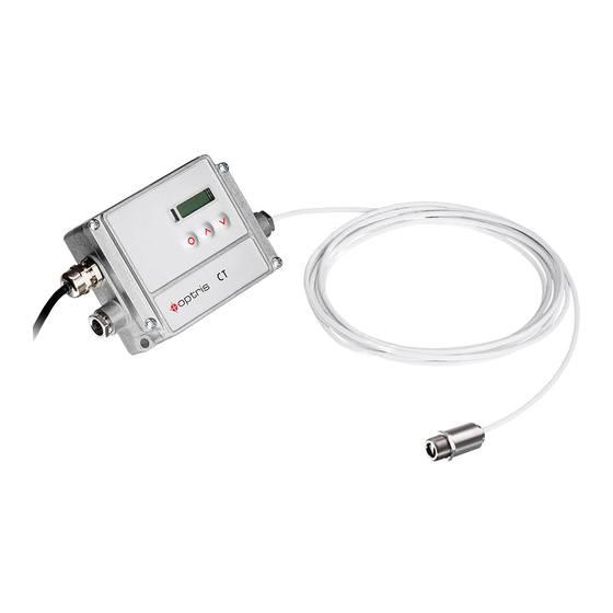
They calculate the surface temperature based on the emitted infrared energy of objects [►9 Basics of Infrared Thermometry]. The sensor housing of the CT head is made of stainless steel (IP65/ NEMA-4 rating) – the sensor electronics is placed in a separate box made of die casting zinc. -
Page 9: Warranty
If the failure results from misuse or neglect the user has to pay for the repair. In that case you may ask for a cost estimate beforehand. 1.3 Scope of Supply ▪ CT sensing head with connection cable and electronic box ▪ Mounting nut ▪ Operators manual 1.800.561.8187... -
Page 10: Maintenance
1.4 Maintenance Lens cleaning: Blow off loose particles using clean compressed air. The lens surface can be cleaned with a soft, humid tissue (moistened with water) or a lens cleaner (e.g. Purosol or B+W Lens Cleaner). Never use cleaning compounds which contain solvents (neither for the lens nor for the housing). 1.800.561.8187 information@itm.com www. -
Page 11: Model Overview
General Information 1.5 Model Overview The sensors of the CT series are available in the following basic versions: Model Model codes Measurement Spectral Typical applications range response LT02 -50 to 600 °C CT LT LT15 8-14 µm non-metallic surfaces LT22 -50 to 975 °C... - Page 12 50 to 400 °C 100 to 600 °C CT 3M 3MH1 150 to 1000 °C 2,3 µm metals at low object temperatures (from 50 °C) 3MH2 200 to 1500 °C 3MH3 250 to 1800 °C 0 to 500 °C 2.2-6 µm metals at low object temperatures (from 0 °C) and...
-
Page 13: Factory Default Settings
1.6 Factory Default Settings The unit has the following presetting at time of delivery: Signal output object temperature 0-5 V Signal output channel 2 (only for CT 4M) Internal head temperature: 0-5 V = 0-70 °C Emissivity 0,970 [LT/ G5/ P3/ P7]... - Page 14 3MH1 3MH2 3MH3 Lower limit temperature range [°C] Upper limit temperature range [°C] 1000 1500 1800 1200 1650 Lower alarm limit [°C] (normally closed) Upper alarm limit [°C] 1000 1200 (normally open) Lower limit signal output Upper limit signal output Temperature unit °C Ambient temperature compensation...
-
Page 15: Technical Data
Dimensions 28 mm x 14 mm or 32 mm x 14 mm, M12x1 89 mm x 70 mm x 30 mm Dimensions CThot/ CT P3/ P7 55 mm x 29,5 mm, M18x1 (with massive housing) Weight 40 g... - Page 16 Pressure resistance (head) 8 bar Software / App (optional) CompactConnect / CompactPlus Connect / IRmobile The functionality of the LCD display can be limited at ambient temperatures below 0 °C The 3M models are only available with 3 m cable length 1.800.561.8187 information@itm.com www.
-
Page 17: Electrical Specifications
CT 4M: 8-30 VDC / 5 V USB / max. 1,2 W Outputs/ analog (For CT 4M output 1 and 2 are freely selectable: Analog mA/mV, Alarm mA/mV, TCK) Channel 1 selectable: 0/ 4–20 mA, 0–5/ 10 V, thermocouple (J or K) or alarm output (Signal source: object temperature) Head temperature [-20...180 °C/ -20...250 °C on LT02H and LT10H] as 0–5 V or 0–10 V... -
Page 18: Measurement Specifications [Lt Models]
2.3 Measurement Specifications [LT models] LT02 LT15 LT22 Temperature range (scalable) -50...600 °C -50...975 °C Ambient temperature (head) -20...130 °C -20...180 °C Storage temperature (head) -40...130 °C -40...180 °C Spectral range 8...14 µm Optical resolution 15:1 22:1 1) 2) 3) System accuracy ±1,0 °C or ±1,0 % 1) 3) - Page 19 Technical Data ε = 1 for ambient temperatures (head) <18 °C and >28 °C; whichever is greater at time constant 200 ms and an object temperature of 25 °C On the LT02 models the head cable must not be moved during the measurement. 1.800.561.8187 information@itm.com www.
-
Page 20: Measurement Specifications [Ctfast/ Cthot]
2.4 Measurement Specifications [CTfast/ CThot] LT15F LT25F LT02H LT10H Temperature range (scalable) -50...975 °C -40...975 °C Ambient temperature (head) -20...120 °C -20...250 °C Storage temperature (head) -40...120 °C -40...250 °C Spectral range 8...14 µm Optical resolution 15:1 25:1 10:1 1) 2) 3) System accuracy ±2°C or ±1% ±1,5°C or ±1%... - Page 21 Technical Data On the CThot models [LT02H/ LT10H] the head cable must not be moved during the measurement. 1.800.561.8187 information@itm.com www. .com...
-
Page 22: Measurement Specifications [1M/ 2M/ 3M/ 4M Models]
2.5 Measurement Specifications [1M/ 2M/ 3M/ 4M models] 1MH1 Temperature range (scalable) 485...1050 °C 650...1800 °C 800...2200 °C 250...800 °C Ambient temperature (head) -20...100 °C -20...125 °C Storage temperature (head) -40...100 °C -40...125 °C Spectral range 1,0 µm 1,6 µm Optical resolution 40:1 75:1... - Page 23 Technical Data 2MH1 Temperature range (scalable) 385...1600 °C 490...2000 °C 50...400 °C 100...600 °C Ambient temperature (head) -20...125 °C -20...85 °C Storage temperature (head) -40...125 °C -40...125 °C Spectral range 1,6 µm 2,3 µm Optical resolution 75:1 22:1 33:1 2) 3) 4) System accuracy ±(0,3 % of reading +2°C) 2) 4)
- Page 24 3MH1 3MH2 3MH3 0…500 °C Temperature range (scalable) 150...1000 °C 200...1500 °C 250...1800 °C 0…70 °C Ambient temperature (head) -20...85 °C -40…85 °C Storage temperature (head) -40...125 °C Spectral range 2,3 µm 2.2-6 µm Optical resolution 75:1 10:1 2) 3) 4) System accuracy ±(0,3 % of reading +2°C) 2) 4)
-
Page 25: Measurement Specifications [G5/ P7 Models]
Technical Data 2.6 Measurement Specifications [G5/ P7 models] Temperature range (scalable) 100...1200 °C 250...1650 °C 50...400 °C 0...710 °C Ambient temperature (head) -20...85 °C 0...75 °C -20...85 °C Storage temperature (head) -40...85 °C Spectral range 5,0 µm 3,43 µm 7,9 µm Optical resolution 10:1 20:1... -
Page 26: Optical Charts
As an alternative to the optical diagrams, the spot size calculator can also be used on the Optris website or via the Optris calculator app. The app can be downloaded for free from the Google Play store (see QR code). - Page 27 Technical Data LT25F Optics: SF D:S: 25:1 LT25F Optics: CF D:S: 25:1 2,0mm@ 50mm D:S (far field) = 6:1 1.800.561.8187 information@itm.com www. .com...
- Page 28 LT22 Optics: SF D:S: 22:1 LT22 Optics: CF D:S: 22:1 2,3mm@ 50mm D:S (far field) = 6:1 1.800.561.8187 information@itm.com www. .com...
- Page 29 Technical Data LT15 LT15F Optics: SF D:S: 15:1 LT15 LT15F Optics: CF D:S: 15:1 3,0mm@ 50mm D:S (far field) = 5:1 1.800.561.8187 information@itm.com www. .com...
- Page 30 LT10H 4ML G5L P7 Optics: SF D:S: 10:1 LT10H Optics: CF1 D:S: 10:1 3,0mm@ 30mm D:S (far field) = 3:1 1.800.561.8187 information@itm.com www. .com...
- Page 31 Technical Data Optics: CF D:S: 10:1 5,0mm@ 50mm D:S (far field) = 4:1 LT02 LT02H Optics: SF D:S: 1.800.561.8187 information@itm.com www. .com...
- Page 32 Optics: SF D:S: 20:1 Optics: CF D:S: 40:1 2,7mm@ 110mm D:S (far field) = 12:1 1.800.561.8187 information@itm.com www. .com...
- Page 33 Technical Data Optics: SF D:S: 40:1 1MH1 2MH1 3MH1-H3 Optics: CF D:S: 75:1 1,5mm@ 110mm D:S (far field) = 14:1 1.800.561.8187 information@itm.com www. .com...
- Page 34 1MH1 2MH1 3MH1-H3 Optics: SF D:S: 75:1 Optics: SF D:S: 22:1 1.800.561.8187 information@itm.com www. .com...
- Page 35 Technical Data Optics: CF1 D:S: 22:1 1,5mm@ 30mm D:S (far field) = 3,5:1 Optics: CF D:S: 22:1 5mm@ 110mm D:S (far field) = 9:1 1.800.561.8187 information@itm.com www. .com...
- Page 36 Optics: SF D:S: 33:1 Optics: CF1 D:S: 33:1 1,0mm@ 30mm D:S (far field) = 4:1 1.800.561.8187 information@itm.com www. .com...
- Page 37 Technical Data Optics: CF D:S: 33:1 3,4mm@ 110mm D:S (far field) = 11:1 Optics: SF D:S: 15:1 1.800.561.8187 information@itm.com www. .com...
-
Page 38: Cf Lens And Protective Window
2.8 CF Lens and Protective Window The optional CF lens allows the measurement of very Typical Transmission values* if the CF lens is small objects and can be used in combination with all used (average values): LT, 1M, 2M, 3M and 4M models. The minimum spot size 0,78 depends on the used sensing head. - Page 39 Technical Data CF lens: Laminar air purge with integrated CF lens with external thread: ACCTCF/ ACCTCFHT CF lens: ACCTCFE/ ACCTCFHTE Protective window: ACCTAPLCF/ ACCTAPLCFHT Protective window with external ACCTPWHT thread: ACCTPWE/ ACCTPWHTE LT25F + CF lens 0,5 mm@ 8 mm 0,5 mm@ 6 mm [ACCTAPLCF] D:S (far field) = 1,6:1 1.800.561.8187...
- Page 40 LT22/ 3ML + CF lens 0,6 mm@ 10 mm 0,6 mm@ 8 mm [ACCTAPLCF] D:S (far field) = 1,5:1 LT15/ LT15F + CF lens 0,8 mm@ 10 mm 0,8 mm@ 8 mm [ACCTAPLCF] D:S (far field) = 1,5:1 1.800.561.8187 information@itm.com www.
- Page 41 Technical Data LT10H + CF lens 1,2 mm@ 10 mm 1,2 mm@ 8 mm [ACCTAPLCF] D:S (far field) = 1,2:1 LT02/ LT02H + CF lens 2,5 mm@ 23 mm 2,5 mm@ 21 mm [ACCTAPLCF] D:S (far field) = 2,5:1 1.800.561.8187 information@itm.com www.
-
Page 42: Mechanical Installation
3 Mechanical Installation The CT sensing heads are equipped with a metrical M12x1-thread and can be installed either directly via the sensor thread or with help of the hex nut (included in scope of supply) to the mounting bracket available. - Page 43 Mechanical Installation The CThot- and CT P3/P7-sensors will be delivered with the massive housing and can be installed via the M18x1-thread. Massive housing (Standard on CThot, P3 and P7) Make sure to keep the optical path clear of any obstacles.
- Page 44 Electronic box The electronic box is also available with closed cover (display and programming keys with no access from outside) [ACCTCOV]. On the CT models LT02, LT02H and LT10H the head cable must not be moved during the measurement. 1.800.561.8187 information@itm.com...
- Page 45 Mechanical Installation Electronic box CT 4M 1.800.561.8187 information@itm.com www. .com...
-
Page 46: Mounting Accessories
3.1 Mounting Accessories Mounting bracket, adjustable in one Mounting bolt with M12x1 thread, Mounting fork with M12x1 thread, axis [ACCTFB] adjustable in one axis [ACCTMB] adjustable in 2 axes [ACCTMG] The Mounting fork can be combined with the Mounting bracket [ACCTFB] using M12x1 thread. - Page 47 Mechanical Installation K40 flange [ACCTKF40GE] for CTLT with Ge window or [ACCTKF40B270] for CT1M, 2M, 3M with B270 window • When changing the windows, the screws must be tightened with a tightening torque of 1 Nm. • Transmission: Ge ≈ 0,91 and B270 ≈ 0,92 (Deviations possible) 1.800.561.8187 information@itm.com www.
-
Page 48: Air Purge Collars
3.2 Air Purge Collars The lens must be kept clean at all times from dust, smoke, fumes and other contaminants in order to avoid reading errors. These effects can be reduced by using an air purge collar. Make sure to use oil-free, technically clean air, only. - Page 49 Mechanical Installation Laminar air purge collar with mounting fork Laminar air purge collar [ACCTAPL] [ACCTAPLMF], adjustable in 2 axes The sideward air outlet prevents a cooling down of the object in short distances. Hose connection: 3x5 mm Thread (fitting): M5 The needed amount of air (approx.
-
Page 50: Further Accessories
Example: LT22 and object with emissivity = 0,85 0,85 x 0,96 = 0,816 Thus the emissivity in the CT has to be set to the resulting value of 0,816. Laser-Sighting tool [D08ACCTLST] battery powered (2x Alcaline AA), for alignment of CT sensing heads. - Page 51 The OEM-Laser-Sighting tool is available with 3,5 m [ACCTOEMLST] and 8 m connection cable [ACCTOEMLSTCB8]. The laser can be connected to the pins 3V SW or PINK (only for CT 4M) and GND [►4 Electrical Installation] and switched on and off via the programming keys or via the software.
- Page 52 Massive housing, stainless steel [D06ACCTMHS] – also available in aluminum (anodized) or brass The Massive housing allows reproducible and stable measurements on applications with significant and short-term variation in ambient temperatures. It can be combined with the CF lens [ACCTCFE] or with the protective window [ACCTPWE].
- Page 53 Mechanical Installation Air purge collar for massive housing (thread M18x1) Mounting bracket for massive housing, [ACCTAPMH] adjustable in one axis [ACCTFBMH] The needed amount of air (approx. 2...10 l/ min.) depends on the application and the installation conditions on-site. 1.800.561.8187 information@itm.com www.
- Page 54 Pipe Adapter and Sighting Tubes The pipe adapter [ACCTPA] allows an assembling of sighting tubes directly on the CT head. The sighting tubes are available in 3 different lengths: ACCTST20 20 mm ACCTST40 40 mm ACCTST88 88 mm Pipe adapter [ACCTPA]...
- Page 55 Mechanical Installation Rail Mount Adapter for Electronic box With the rail mount adapter the CT electronics can be mounted easily on a DIN rail (TS35) according EN50022. Rail Mount Adapter [ACCTRAIL] Tilt Assembly for CT heads With this mounting accessory a fine adjustment of the CT head with an off-axis angle +/- 6,5°...
- Page 56 The IR App Connector is used to connect the sensor to a smartphone or tablet (► 7 IRmobile app). The connector cable can be also used for the connection to your PC in combination with the software CompactConnect/ CompactPlus Connect (►8 Software CompactConnect/ CompactPlus Connect). IR app Connector: USB programming adaptor [ACCTIAC (for CT 4M: ACCTMIAC)] 1.800.561.8187 information@itm.com www.
-
Page 57: Electrical Installation
Electrical Installation 4 Electrical Installation 4.1 Cable Connections For the electrical installation of the CT please open at first the cover of the electronic box (4 screws). Below the display are the screw terminals for the cable connection. 4.1.1 Designation [models LT/ G5/ P3/ P7] +8…36 VDC... -
Page 58: Designation [Models 1M/ 2M/ 3M]
4.1.2 Designation [models 1M/ 2M/ 3M] +8…36 VDC Power supply Ground (0 V) of power supply Ground (0 V) of internal in- and outputs Alarm 2 (Open collector output) OUT-TC Analog output thermocouple (J or K) OUT-mV/mA Analog output object temperature (mV or F1-F3 Functional inputs Ground (0 V) -
Page 59: Designation [Models 4M]
Electrical Installation 4.1.3 Designation [models 4M] +8…30 VDC Power supply Ground (0 V) of power supply Ground (0 V) of internal in- and outputs Alarm 2 (Open collector output) OUT-1 Analog output mA, mV, TCK OUT-2 Analog output mA, mV, TCK I/O1-I/O3 In- and outputs Ground (0 V) -
Page 60: Power Supply
4.1.4 Power supply Please use a stabilized power supply unit with an output voltage in the range of 8–36 VDC (CT 4M: 8-30 VDC) which can supply 100 mA. The ripple should be max. 200 mV. Please do never connect a supply voltage to the analog outputs as this will destroy the... -
Page 61: Cable Assembling
Electrical Installation 4.1.5 Cable Assembling The cable gland M12x1,5 allows the use of cables with a diameter of 3 to 5 mm. Remove the isolation from the cable (40 mm power supply, 50 mm signal outputs, 60 mm functional inputs). Cut the shield down to approximately 5 mm and spread the strands out. -
Page 62: Ground Connection
4.2 Ground Connection 4.2.1 1M, 2M, 3M models At the bottom side of the mainboard PCB you will find a connector (jumper) which has been placed from factory side as shown in the picture [bottom and middle pin connected]. In this position the ground connections (GND power supply/ outputs) are connected with the ground of the electronics housing. -
Page 63: Ltf, Lth, G5, P3, P7 Models
Electrical Installation 4.2.3 LT, LTF, LTH, G5, P3, P7 models At the bottom side of the mainboard PCB you will find a connector (jumper) which has been placed from factory side as shown in the picture [left and middle pin connected]. In this position the ground connections (GND power supply/ outputs) are connected with the ground of the electronics housing. -
Page 64: Exchange Of The Sensing Head
Inside a certain model group any exchange of sensing heads and electronics is possible. The sensing heads and electronics of the CTfast models (LT15F and LT25F) and CT 4M cannot be exchanged. 4.3.1 Entering of the Calibration Code Every head has a specific calibration code, which is printed on the head cable. -
Page 65: Sensing Head Cable
4.3.2 Sensing Head Cable On all CT models (exception 3M, P3, P7) the sensing head cable can be shortened if necessary. On the models 1M, 2M and CTfast the sensing head cable can be shortened by max. 3 m. A shortening of the cable will cause an additional measuring error of about 0,1 K/ m. -
Page 66: Outputs And Inputs
5.1 Analog Outputs The CT has two analog output channels. CAUTION: Please do never connect a supply voltage to the With the CT 4M the outputs are freely analog outputs as this will destroy the output. selectable. The CT is not a 2-wire sensor! 5.1.1... -
Page 67: Digital Interfaces
Please pay attention to the notes on the according interface manuals. 5.3 Relay Outputs The CT can be optionally equipped with a relay output. The relay board will be installed the same way as the digital interfaces. A simultaneous installation of a digital interface and the relay outputs is not possible. -
Page 68: Functional Inputs (Not For Ct 4M)
To make advanced settings (change of low- and high alarm) a digital interface (USB, RS232) and the software is needed. 5.4 Functional Inputs (not for CT 4M) The three functional inputs F1 – F3 can be programmed with the software only. -
Page 69: I/O Pins (Only For Ct 4M)
Outputs and Inputs 5.5 I/O pins (only for CT 4M) The CT 4M has three digital pins which can be programmed as outputs (digital) or as inputs (digital or analog) using the CompactPlus Connect software. The following functions are available:... -
Page 70: Alarms
To activate the according output channel has to be switched into digital mode. For this purpose the software CompactConnect/ CompactPlus Connect is required. On the CT model 4M both outputs are freely selectable. Analog mA/mV, Alarm mA/mV and TCK are available. - Page 71 ] a digital interface (e.g. USB, RS232) including the software Proc Head CompactConnect is needed. On the CT model 4M visual alarms are independent of the alarm settings. In the CompactPlus Connect software these can be defined as desired. 1.800.561.8187 information@itm.com www.
-
Page 72: Open Collector Output / Al2
5.6.2 Open collector output / AL2: • The transistor acts as a switch. In case of alarm, the contact is closed. • A load/consumer (Relay, LED or a resistor) must always be connected. • The alarm voltage (here 24 V) must not be connected directly to the alarm output (short circuit). -
Page 73: Operating
The signal processing features Peak hold and Valley hold cannot be selected simultaneously. Factory Default Setting To set the CT back to the factory default settings, please press at first the Down-key and then the Mode-key and keep both pressed for approx. 3 seconds. - Page 74 Display Mode [Sample] Adjustment Range 142.3C Object temperature (after signal processing) [142,3 °C] fixed 127CH Head temperature [127 °C] fixed 25CB Box temperature [25 °C] fixed 142CA Current object temperature [142 °C] fixed ð MV5 Signal output channel 1 [0-5 V] ð...
- Page 75 Operating ð MV5 Selection of the Output signal. By pressing Up or Down the different output signals can be selected (see table). E0.970 Setup of Emissivity. Pressing Up increases the value, Down decreases the value (also valid for all further functions). The emissivity is a material constant factor to describe the ability of the body to emit infrared energy [►10 Emissivity].
- Page 76 Signal graph with P---- ▬ TProcess with Peak Hold (Hold time = 1s) ▬ TActual without post processing 1.800.561.8187 information@itm.com www. .com...
- Page 77 Operating Setup of the Lower limit of temperature range. The minimum difference between lower and upper limit is 20 K. If you set the lower limit to a value ≥ upper limit the upper limit will be adjusted to [lower limit + 20 K] automatically. n 500.0 Setup of the Upper limit of the temperature range.
- Page 78 Especially if there is a big difference between the ambient temperature at the object and the head temperature the use of Ambient temperature compensation is recommended. M 01 Setup of the Multidrop address. In a RS485 network each sensor will need a specific address.
- Page 79 Operating CT 4M Display Mode [Sample] Display TPROC 320.9 Process temperature (after signal processing) [320,9 °C] fixed T INT 50.1 Detector Temperature [50,1 °C] fixed T BOX 38.6 Electronic box Temperature [38,6 °C] fixed EMISS 1.000 Emissivity [1,000] 0,100 ... 1,100 TRANS 1.000...
- Page 80 AVG 0.020 Setup of Average time. In this mode an arithmetic algorithm will be performed to smoothen the signal. The set time is the time constant. This function can be combined with all other post processing functions. The shortest value is 0,001 s. If the value is set to 0.0 the function is deactivated.
- Page 81 Operating value of the hysteresis before the algorithm takes it as a new minimum value. U °C Setup of the Temperature unit [°C or °F]. M 01 Setup of the Multidrop address. In a RS485 network each sensor will need a specific address.
- Page 82 ▬ T with Peak Hold (Hold time = 1s) Proc ▬ T without post processing 1.800.561.8187 information@itm.com www. .com...
- Page 83 Operating ▬ T with Advanced peak hold (Threshold = 80 °C/ Hysteresis = 20 °C) Proc ▬ T without post processing 1.800.561.8187 information@itm.com www. .com...
-
Page 84: Error Messages
6.2 Error messages The display of the sensor can show the following error messages: LT/ G5/ P3/ P7 models: OVER Object temperature too high UNDER Object temperature too low ^^^CH Head temperature too high Head temperature too low 1M/ 2M/ 3M models: 1. -
Page 85: Irmobile App
This app works on most Android devices running 5.0 or higher with a micro USB or USB-C port supporting USB-OTG (On The Go). It is easy to operate: after you plug your CT device to your phone or tablet, the app will start automatically. The device is powered by your phone. Different digital temperature values can be displayed in the temperature time diagram. - Page 86 ➢ Integrated simulator Supported for: ➢ Optris pyrometers: Compact series, high performance series and video thermometers ➢ Optris IR cameras: PI and Xi series ➢ For android devices running 5.0 or higher with a micro USB or USB-C port supporting USB-OTG (On The Go) 1.800.561.8187...
-
Page 87: Software Compactconnect/ Compactplus Connect
Software CompactConnect/ CompactPlus Connect 8 Software CompactConnect/ CompactPlus Connect 8.1 Installation Unzip and open the program and start the Minimum system requirements: CDsetup.exe. Follow instructions ▪ Windows 7, 8, 10 wizard until the installation is finished. ▪ USB interface ▪ Hard disc with at least 30 MByte free space ▪... - Page 88 Main Features: ▪ Graphic display temperature trends automatic data logging analysis documentation ▪ Complete sensor setup and remote controlling ▪ Adjustment of signal processing functions ▪ Programming of outputs and functional inputs CompactConnect CompactPlus Connect 1.800.561.8187 information@itm.com www. .com...
-
Page 89: Communication Settings
8.2.2 Protocol All sensors of the CT series are using a binary protocol. Alternatively, they can be switched to an ASCII protocol (only LT versions). To get a fast communication the protocol has no additional overhead with CR, LR or ACK bytes. -
Page 90: Ascii Protocol
8.2.3 ASCII protocol The models LT02, LT15, LT22, LT02H and LT10H can be switched to ASCII by changing the first figure of block 3 of the head calibration code. This figure has to be changed from 0 to 4 (old sensing head) or 8 to C (new sensing head). -
Page 91: Saving Of Parameter Settings
8.2.4 Saving of parameter settings After power on of the CT sensor the flash mode is active. It means, changed parameter settings will be saved in the CT-internal Flash-EEPROM and will be kept also after the sensor is switched off. -
Page 92: Basics Of Infrared Thermometry
9 Basics of Infrared Thermometry Depending on the temperature each object emits a certain amount of infrared radiation. A change in the temperature of the object is accompanied by a change in the intensity of the radiation. For the measurement of “thermal radiation”... -
Page 93: Emissivity
Emissivity 10 Emissivity 10.1 Definition The intensity of infrared radiation, which is emitted by each body, depends on the temperature as well as on the radiation features of the surface material of the measuring object. The emissivity (ε – Epsilon) is used as a material constant factor to describe the ability of the body to emit infrared energy. -
Page 94: Characteristic Emissivity
and take the temperature of the sticker. Afterwards, determine the temperature of the adjacent area on the measuring object and adjust the emissivity according to the value of the temperature of the sticker. ► Cove a part of the surface of the measuring object with a black, flat paint with an emissivity of 0,98. Adjust the emissivity of your infrared thermometer to 0,98 and take the temperature of the colored surface. -
Page 95: Appendix A - Table Of Emissivity For Metals
Appendix A – Table of Emissivity for metals Appendix A – Table of Emissivity for metals Material typical Emissivity Spectral response 1,0 µm 1,6 µm 5,1 µm 8-14 µm Aluminium non oxidized 0,1-0,2 0,02-0,2 0,02-0,2 0,02-0,1 polished 0,1-0,2 0,02-0,1 0,02-0,1 0,02-0,1 roughened 0,2-0,8... - Page 96 Material typical Emissivity Spectral response 1,0 µm 1,6 µm 5,1 µm 8-14 µm Lead polished 0,35 0,05-0,2 0,05-0,2 0,05-0,1 roughened 0,65 oxidized 0,3-0,7 0,2-0,7 0,2-0,6 Magnesium 0,3-0,8 0,05-0,3 0,03-0,15 0,02-0,1 Mercury 0,05-0,15 0,05-0,15 0,05-0,15 Molybdenum non oxidized 0,25-0,35 0,1-0,3 0,1-0,15 oxidized 0,5-0,9 0,4-0,9...
-
Page 97: Appendix B - Table Of Emissivity For Non-Metals
Appendix B – Table of Emissivity for non-metals Appendix B – Table of Emissivity for non-metals Material typical Emissivity Spectral response 1,0 µm 2,2 µm 5,1 µm 8-14 µm Asbestos 0,95 Asphalt 0,95 0,95 Basalt Carbon non oxidized 0,8-0,9 0,8-0,9 0,8-0,9 graphite 0,8-0,9... -
Page 98: Appendix C - Smart Averaging
Appendix C – Smart Averaging The average function is generally used to smoothen the output signal. With the adjustable parameter time this function can be optimal adjusted to the respective application. One disadvantage of the average function is that fast temperature peaks which are caused by dynamic events are subjected to the same averaging time. -
Page 99: Appendix D - Declaration Of Conformity
Appendix D – Declaration of Conformity Appendix D – Declaration of Conformity 1.800.561.8187 information@itm.com www. .com...
Need help?
Do you have a question about the CT and is the answer not in the manual?
Questions and answers