Table of Contents
Advertisement
Quick Links
Advertisement
Table of Contents

Related Manuals for optris CTratio 1M Series


Summary of Contents for optris CTratio 1M Series
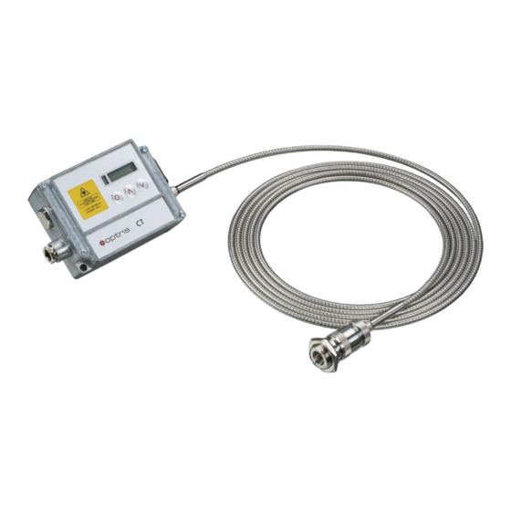
- Page 1 Operator‘s Manual optris ® CTratio 1M/ 2M Fiber Optics Ratio Thermometer...
- Page 2 Optris GmbH Ferdinand-Buisson-Str. 14 13127 Berlin Germany Tel.: +49 30 500 197-0 Fax: +49 30 500 197-10 E-mail: info@optris.global Internet: www.optris.global...
-
Page 3: Table Of Contents
Table of Contents Table of Contents Table of Contents ............................. 3 General Information ..........................7 Description ............................7 Warranty ............................9 Scope of Supply ..........................9 Maintenance ........................... 10 Safety Note ............................. 10 Cautions ............................10 Factory Default Settings ......................... 11 Technical Data ............................ - Page 4 Measurement Specifications [2M models] ..................16 Optics ............................. 17 Mechanical Installation .......................... 20 Accessories ............................ 23 Laser Sighting ..........................25 Electrical Installation ..........................26 Cable Connections ......................... 26 Ground Connection ........................28 Outputs and Inputs ..........................29 Analog Output ..........................29 I/O pins ............................
- Page 5 Table of Contents Operating ..............................34 Sensor Setup ..........................34 IRmobile app ............................38 Software Ratio Connect ........................40 Installation ............................40 Communication Settings ........................ 42 8.2.1 Serial Interface ........................... 42 8.2.2 Protocol ............................42 Basics of Infrared Thermometry......................43 The Ratio Principle .........................
- Page 6 10.4 Characteristic Slope Values ......................48 10.5 Determination of unknown Slope values ..................48 10.6 Attenuation ............................. 48 Appendix A – Emissivity Table Metals ......................50 Appendix B – Emissivity Table Non Metals ....................52 Appendix C – Smart Averaging ........................53 Appendix D –...
-
Page 7: General Information
1.1 Description Thank you for choosing the optris® CTratio infrared thermometer. The sensors of the optris CTratio series are noncontact infrared temperature sensors. They calculate the surface temperature based on the emitted infrared energy of objects. The CTratio can work in the 1-color-mode as well as in the ratio- or 2-color-mode [►9 Basics of Infrared Thermometry]. - Page 8 The CTratio sensing head is a sensitive optical system. Please use only the thread for mechanical installation. Avoid abrupt changes of the ambient temperature. Avoid mechanical violence on the head – this may destroy the system (expiry of warranty). ...
-
Page 9: Warranty
General Information 1.2 Warranty Each single product passes through a quality process. Nevertheless, if failures occur please contact the customer service at once. The warranty period covers 24 months starting on the delivery date. After the warranty is expired the manufacturer guarantees additional 6 months warranty for all repaired or substituted product components. -
Page 10: Maintenance
1.4 Maintenance Lens cleaning: Blow off loose particles using clean compressed air. The lens surface can be cleaned with a soft, humid tissue (moistened with water) or a lens cleaner (e.g. Purosol or B+W Lens Cleaner). Never use cleaning compounds which contain solvents (neither for the lens nor for the housing). 1.5 Safety Note The CTratio is equipped with an integrated laser that serves to align the optics with the target. -
Page 11: Factory Default Settings
General Information 1.7 Factory Default Settings The unit has the following presetting at time of delivery: Output 1 Analog: TProc/ max. temperature range (according to model) = 4-20 mA Output 2 Analog: Attenuation/ 0-100 % = 0-20 mA Emissivity 1,000 Slope 1,000 Averaging (AVG) - Page 12 Smart Averaging means a dynamic average adaptation at high signal edges [activation via software only]. ►Appendix C – Smart Averaging...
-
Page 13: Technical Data
Technical Data 2 Technical Data 2.1 General Specifications Sensing head Electronic box Environmental rating IP65 (NEMA-4) 0...50 °C (2M) / 0…60 °C (1M) Ambient Temperature -20...200 °C (optional to 315 °C) Storage temperature -40...200 °C -40...85 °C Relative humidity 10...95%, non condensing Material stainless steel die casting zinc... -
Page 14: Electrical Specifications
2.2 Electrical Specifications Power Supply 8–30 VDC Power max. 5 W Aiming laser 520 nm, <1 mW, On/ Off via programming keys or software Outputs/ analog 2x 0/ 4–20 mA (12 bit) / optional: 2x 0/ 4–20 mA (16 bit) isolated Digital I/O pins 3 programmable in-/ outputs, usable as: ... -
Page 15: Measurement Specifications [1M Models]
Technical Data 2.3 Measurement Specifications [1M models] 1MH1 1 color: 900…3000 °C Temperature range (scalable) 1 color: 450...1400 °C 1 color: 650...2000 °C 2 color: 1000…3000 °C 2 color: 525...1400 °C 2 color: 700...2000 °C Spectral range 0,8 - 1,1 µm Optical resolution 38:1 100:1... -
Page 16: Measurement Specifications [2M Models]
2.4 Measurement Specifications [2M models] 2MH1 1 color: 500…3000 °C Temperature range (scalable) 1 color: 250...1000 °C 1 color: 375...1500 °C 2 color: 550…3000 °C 2 color: 275...1000 °C 2 color: 400...1500 °C Spectral range 1,45 - 1,75 µm Optical resolution 38:1 50:1 100:1... -
Page 17: Optics
The distance is always measured from the front edge of the sensing head. As an alternative to the optical diagrams, the spot size calculator can also be used on the Optris website (https://www.optris.global/spot-size-calculator) or via the Optris calculator app. The app can be downloaded for free from the Google Play Store (see QR code). - Page 18 1ML / 2ML (D:S=38:1) Spot size 13,2 19,7 26,3 39,5 52,6 65,8 131,6 Measurement distance 1000 1500 2000 2500 5000 2MH (D:S=50:1) Spot size Measurement distance 1000 1500 2000 2500 5000 1MH / 1MH1 / 2MH1 (D:S=100:1) Spot size Measurement distance 1000 1500 2000...
- Page 19 Technical Data Sensor placement [1C mode] The size of the measuring object and the optical resolution of the infrared thermometer determine the maximum distance between sensing head and measuring object. In order to prevent measuring errors the object should fill out the field of view of the optics completely. Consequently, the spot should at all times have at least the same size like the object or should be smaller than that.
-
Page 20: Mechanical Installation
3 Mechanical Installation The CTratio sensing heads are equipped with a metrical M18x1-thread and can be installed either directly via the sensor thread or with help of the hex nuts (1 piece included in scope of supply) to the mounting bracket available. - Page 21 Mechanical Installation Electronic box The electronic box is also available with closed cover (display and programming keys with no access from outside) [ACCTCOV].
- Page 22 The CTratio pyrometer is equipped with a vario optics. This enables you to focus the device from a distance of 300 mm to infinity. To focus the sensor, loosen the knurled screw (1) on the head. Now you can focus the device on the head (2).
-
Page 23: Accessories
Mechanical Installation 3.1 Accessories Mounting bracket, adjustable in one axis Air purge collar [ACCTAPMH] [ACCTFBMH] The lens must be kept clean at all times from dust, smoke, fumes and other contaminants in order to avoid reading errors (in the 1-color-mode). These effects can be reduced by using an air purge collar. Make sure to use oil-free, technically clean air, only. - Page 24 Rail Mount Adapter for Electronic box With the rail mount adapter the CTratio electronics can be mounted easily on a DIN rail (TS35) according EN50022. ACCTRAIL...
-
Page 25: Laser Sighting
Mechanical Installation 3.2 Laser Sighting The integrated laser sighting supports the alignment and focusing of the optics. The size of the laser dot is equal to the real measurement spot size at any distance. The laser can be activated/ deactivated via the programming keys on the unit or via the software. -
Page 26: Electrical Installation
4 Electrical Installation 4.1 Cable Connections The supplied USB cable can be connected to the side of the electronics box. The device can be operated directly via the Ratio Connect software or the IRmobile App. For the electrical installation of further interfaces and when using the in- /outputs please open at first the cover of the electronic box (4 screws). - Page 27 Electrical Installation Please do never connect a supply voltage to the analog outputs as this will destroy the output! The CTratio is not a 2-wire sensor! Power supply Please use a power supply unit with an output voltage of 8–30 VDC with a power of 5 W. The ripple should be max.
-
Page 28: Ground Connection
Use shielded cables only. The sensor shield has to be grounded. 4.2 Ground Connection On the mainboard PCB you will find a black wire which is connecting factory-default the ground connections (GND power supply/ outputs) with the ground of the electronics housing. Removing the ground connection is not recommended. -
Page 29: Outputs And Inputs
Outputs and Inputs 5 Outputs and Inputs The CTratio has two analog output and three digital I/O pins (programmable as in- or output). 5.1 Analog Output The selection of the signal on output channel 1 and 2 (0/4-20 mA) can be done via the software Ratio Connect [►8 Software Ratio Connect] or the IRmobile app [►7 IRmobile app]. -
Page 30: I/O Pins
5.2 I/O pins The CTratio has three digital pins which can be programmed as outputs (digital) or as inputs (digital or analog) using the Ratio Connect software. The following functions are available: Function I/O pin acts as Description Digital Alarm output digital Open collector output/ definition as HIGH- or LOW alarm via norm. -
Page 31: Programming Interface
Outputs and Inputs 5.3 Programming Interface The CTratio has on the side of the electronic box a USB interface for programming and running the sensor. The USB cable is included in the scope of supply. As an option, the device can also be equipped with an RS232 or RS485 interface. -
Page 32: Relay Outputs
5.4 Relay Outputs The CTratio can be optionally equipped with a relay output. The relay board will be installed the same way as the programming interface. The relay board provides two fully isolated switches, which have the capability to switch max. -
Page 33: Alarms
Outputs and Inputs 5.5 Alarms The CTratio has the following Alarm All alarms have a fixed hysteresis of 2 K. features: Visual Alarms These alarms will cause a change of the color of the LCD display. Digital Alarm 1, 2, 3 All the I/O pins can be programmed as alarm output. -
Page 34: Operating
6 Operating After power up the unit the sensor starts an initializing routine for some seconds. During this time the display will show INIT. After this procedure the process temperature is shown in the display. The display backlight color changes according to the alarm settings [►5.5 Alarms]. 6.1 Sensor Setup The programming keys Mode, Up and Down enable the user to set the sensor on-site. - Page 35 Operating Display Mode [Sample] Adjustment Range S OFF Laser Sighting ON/ OFF T RAT 878.9 Ratio temperature after signal processing) [878,9 °C] fixed T1 897,1 1 channel temperature [879,1 °C] fixed T2 879,0 2 channel temperature [879,0 °C] fixed ATT 0.0 Attenuation[0,0 %] fixed T DET 50.1...
- Page 36 Activating (ON) and Deactivating (OFF) of the Sighting Laser. By pressing Up or Down S OFF the laser can be switched on and off. The Slope is the quotient of the emissivity’s of both of the overlapping wavelengths and SLOPE therewith the deciding parameter for measurements in 2-color-mode.
- Page 37 Operating values which are lower than their predecessors will only be taken over if the temperature has fallen below the Threshold value beforehand. If Hysteresis is activated a peak in addition must decrease by the value of the hysteresis before the algorithm takes it as a new peak value.
-
Page 38: Irmobile App
7 IRmobile app The CTratio sensor has a direct connection to an Android smartphone or tablet. All you have to do is download the IRmobile app for free in the Google Play store. This can also be done via the QR code. The supplied USB cables can be used for connection to the device. With IRmobile you are able to monitor and analyse your infrared temperature measurement on a connected smartphone or tablet. - Page 39 Integrated simulator Supported for: Optris pyrometers: Compact series, high performance series and video thermometers Optris IR cameras: PI and Xi series For android devices running 5.0 or higher with a micro USB or USB-C port supporting USB-OTG (On...
-
Page 40: Software Ratio Connect
Hard disc with at least 30 MByte free space At least 128 MByte RAM The software can be downloaded via the Optris website under the following link: https://www.optris.global/downloads-software The installation wizard will place a launch icon on the desktop and in the start menu: [Start]\Programs\RatioConnect. - Page 41 Software Ratio Connect Main Features: Graphic display for temperature trends and automatic data logging analysis documentation Complete sensor setup and remote controlling Adjustment of signal processing functions Programming of outputs and functional inputs...
-
Page 42: Communication Settings
8.2 Communication Settings 8.2.1 Serial Interface Baudrate: 115,2 / 921,6 kBaud Data bits: Parity: none Stop bits: Flow control: 8.2.2 Protocol All sensors of the CT series are using a binary protocol. -
Page 43: Basics Of Infrared Thermometry
Basics of Infrared Thermometry 9 Basics of Infrared Thermometry Depending on the temperature each object emits a certain amount of infrared radiation. A change in the temperature of the object is accompanied by a change in the intensity of the radiation. For the measurement of “thermal radiation”... -
Page 44: The Ratio Principle
9.1 The Ratio Principle The 2-color ratio technology makes possible accurate and repeatable temperature measurements that are free from dependence on absolute radiated energy values. In use, a 2-color sensor determines temperature from the ratio of the radiated energies in two separate wavelength bands (colors). The benefits of 2-color sensors are that accurate measurements can be made under the following conditions: ►... - Page 45 Basics of Infrared Thermometry 1-color sensors see polluted atmosphere and dirty windows and lenses as a reduction in energy and give much lower than actual temperature readings. Targets Smaller Than Field of View When a target is not large enough to fill the field of view, or if the target is moving within the field of view, radiated energies are equally reduced, but the ratio of the energies is unaffected and measured temperatures remain accurate.
-
Page 46: Emissivity
10 Emissivity 10.1 Definition The intensity of infrared radiation, which is emitted by each body, depends on the temperature as well as on the radiation features of the surface material of the measuring object. The emissivity (ε – Epsilon) is used as a material constant factor to describe the ability of the body to emit infrared energy. -
Page 47: Characteristic Emissivity
Emissivity and take the temperature of the sticker. Afterwards, determine the temperature of the adjacent area on the measuring object and adjust the emissivity according to the value of the temperature of the sticker. ► Cove a part of the surface of the measuring object with a black, flat paint with an emissivity of 0,98. Adjust the emissivity of your infrared thermometer to 0,98 and take the temperature of the colored surface. -
Page 48: Characteristic Slope Values
10.4 Characteristic Slope Values The slope is the quotient of the emissivity of both of the overlapping wavelength bands. The factory default value for the slope is 1,000. The following slopes are typical reference values. The real slope can vary depending on the metal alloy and surface finish. - Page 49 Emissivity This figure is showing the typical temperature reading of a ratio thermometer optris CTratio in both the 1- color- and the 2-color-mode in addiction of increasing contamination of the optical transmission path in- between the target and the ratio thermometer. Due to the ratio principle the 2 channel signal (upper curve) stays very stable over a wide range of attenuation up to over 90 %.
-
Page 50: Appendix A - Emissivity Table Metals
Appendix A – Emissivity Table Metals Material typical Emissivity Spectral response 1,0 µm 1,6 µm 5,1 µm 8-14 µm Aluminium non oxidized 0,1-0,2 0,02-0,2 0,02-0,2 0,02-0,1 polished 0,1-0,2 0,02-0,1 0,02-0,1 0,02-0,1 roughened 0,2-0,8 0,2-0,6 0,1-0,4 0,1-0,3 oxidized 0,2-0,4 0,2-0,4 Brass polished 0,35 0,01-0,05... - Page 51 Appendix A – Emissivity Table Metals Material typical Emissivity Spectral response 1,0 µm 1,6 µm 5,1 µm 8-14 µm Lead polished 0,35 0,05-0,2 0,05-0,2 0,05-0,1 roughened 0,65 oxidized 0,3-0,7 0,2-0,7 0,2-0,6 Magnesium 0,3-0,8 0,05-0,3 0,03-0,15 0,02-0,1 Mercury 0,05-0,15 0,05-0,15 0,05-0,15 Molybdenum non oxidized 0,25-0,35...
-
Page 52: Appendix B - Emissivity Table Non Metals
Appendix B – Emissivity Table Non Metals Material typical Emissivity Spectral response 1,0 µm 2,2 µm 5,1 µm 8-14 µm Asbestos 0,95 Asphalt 0,95 0,95 Basalt Carbon non oxidized 0,8-0,9 0,8-0,9 0,8-0,9 graphite 0,8-0,9 0,7-0,9 0,7-0,8 Carborundum 0,95 Ceramic 0,8-0,95 0,8-0,95 0,95 Concrete... -
Page 53: Appendix C - Smart Averaging
Appendix C – Smart Averaging Appendix C – Smart Averaging The average function is generally used to smoothen the output signal. With the adjustable parameter time this function can be optimal adjusted to the respective application. One disadvantage of the average function is that fast temperature peaks which are caused by dynamic events are subjected to the same averaging time. -
Page 54: Appendix D - Declaration Of Conformity
Appendix D – Declaration of Conformity...
Need help?
Do you have a question about the CTratio 1M Series and is the answer not in the manual?
Questions and answers