Table of Contents
Advertisement
Quick Links
Advertisement
Table of Contents

Related Manuals for optris LT


Summary of Contents for optris LT
- Page 1 ® optris CSmicro LT/ 2WLT/ 2W2M/ 3M ¯¯¯¯¯¯¯¯¯¯¯¯¯¯¯¯¯¯¯¯¯¯¯¯¯¯¯¯¯¯¯¯¯¯¯¯¯¯¯¯¯¯¯¯¯¯¯¯¯¯¯¯¯¯¯¯¯¯¯¯¯¯¯¯¯¯¯¯¯¯¯¯¯¯¯¯¯¯¯¯¯¯¯¯¯¯¯¯¯¯¯¯¯¯¯¯¯¯¯¯¯¯¯¯¯¯¯¯¯¯¯¯¯¯¯¯¯¯¯¯¯¯¯¯¯¯¯¯¯¯¯¯¯¯¯¯¯¯¯¯¯¯¯¯¯¯¯¯¯¯¯¯¯¯¯¯¯¯¯¯¯¯¯¯¯¯¯¯¯¯¯¯¯¯¯¯¯¯¯¯¯¯¯¯¯¯¯¯¯¯¯¯¯¯¯¯¯¯¯¯¯¯¯¯¯¯¯¯¯¯¯¯¯¯¯¯¯¯¯¯ Infrared Thermometer Operators manual...
- Page 2 Messtechnik Schaffhausen GmbH Mühlenstrasse 4 , CH - 8260 Stein am Rhein Telefon + 41 52-672 50 00 Telefax + 41 52-672 50 01 www.mts.ch, e-mail: info @ mts.ch Messen Prüfen Automatisieren www.mts.ch...
- Page 3 The freight costs will be paid by the sender. The manufacturer reserves the right to exchange components of the product instead of repairing it. If the failure results from misuse or neglect the user has to pay for the repair. In that case you may ask for a cost estimate beforehand. optris CSmicro – E2015-12-A...
-
Page 4: Table Of Contents
Temperature Code Indication interface Appendix E – Declarations of Conformity Mechanical Installation Mounting Accessories [LT/ 3M/ 2WLT/ 2W2M] Mounting Accessories [2WhsLT] Air Purge Collars [LT/ 3M/ 2WLT/ 2W2M] Air Purge Collar [2WhsLT] Further Accessories Electrical Installation Analog Mode optris CSmicro – E2015-12-A... -
Page 5: Description
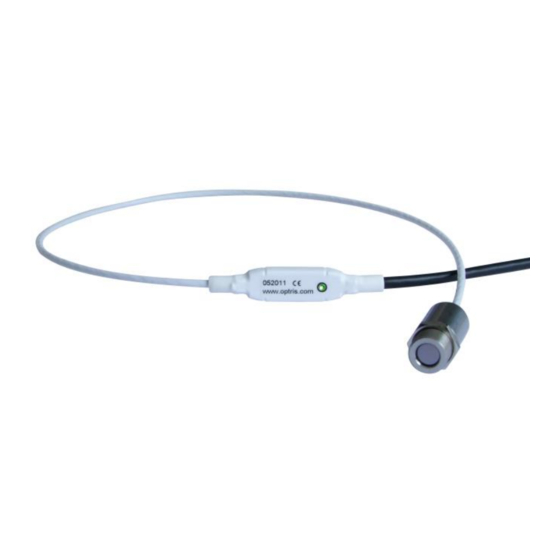
They calculate the surface temperature based on the emitted infrared energy of objects [► Basics of Infrared Thermometry]. The sensor housing of the optris CSmicro is made of stainless steel (IP65/ NEMA-4 rating) – the sensor electronics is integrated inside the connection cable. -
Page 6: Cautions
2W hsLT -20 to 150 °C 8-14 µm 4-20 mA 15:1 0,025 K resolution 2W2M 2W 2ML 250 to 800 °C 1,6 µm 4-20 mA 40:1 2W 2MH 385 to 1600 °C 1,6 µm 4-20 mA 75:1 optris CSmicro – E2015-12-A... -
Page 7: Factory Default Settings
2 °C 2 °C Ambient temperature source: internal (head) Status-LED function: Self diagnostic Input (IN/ OUT/ green): inactive Output (OUT/ yellow): mV output Vcc adjust: inactive Signal processing: Hold mode: Calibration: Gain 1,000/ Offset 0,0 Failsafe: inactive optris CSmicro – E2015-12-A... - Page 8 2 °C Ambient temperature source: internal (head) Status-LED function: Self diagnostic Input (IN/ OUT/ green): Communication input Output (OUT/ yellow): Communication output Vcc adjust: inactive Signal processing: Hold mode: Calibration: Gain 1,000/ Offset 0,0 Failsafe: inactive optris CSmicro – E2015-12-A...
- Page 9 Output (OUT/ yellow): Communication output Vcc adjust: inactive Signal processing: Hold mode: Calibration: Gain 1,000/ Offset 0,0 Failsafe: inactive Smart Averaging means a dynamic average adaptation at high signal edges [activation/ deactivation via software only]. ► Appendix C optris CSmicro – E2015-12-A...
- Page 10 For a usage of the CSmicro LT for online maintenance applications (in electrical cabinets e.g.) the following recommend settings are already included in the factory default setting (but not active): At 3-state output the following settings are default: Pre-alarm difference: 2 °C...
-
Page 11: Technical Data
10...95 %, non condensing Material Stainless steel Dimensions 28 mm x 14 mm (head) [LT/ 3M/ 2WLT/ 2W2M] 55 mm x 29,5 mm (head incl. massive housing) [2WhsLT] 35 mm x 12 mm (electronics) Weight 42 g [LT/ 3M/ 2WLT/ 2W2M] 200 g [2WhsLT] head –... -
Page 12: Electrical Specifications
Electrical Specifications Used pin Function LT / 3M IN/ OUT Analog 0-5 V or 0-10 V / scalable 4-20 mA/ scalable (current loop between Power and GND pin) Alarm output voltage adjustable; N/O or N/C output current adjustable; N/O or N/C (current loop between... - Page 13 500 mA if the mV output is not used High level: > 0,8 V/ Low level: < 0,8 V Reset of peak or valley hold by High level at IN/ OUT pin (Low: open or GND / High: >2,4 V...11 V) Reset of peak or valley hold by Low level at IN/ OUT pin (Low: GND / High: open or >1 V...11 V)
-
Page 14: Pin Configuration
Current loop (+)/ Alarm output yellow green IN/ OUT Trigger input/ RxD/ Open collector output brown Current loop (-)/ Ground () black Shield Shield You will find a detailed description of the different sensor connections in chapter ► Electrical Installation. optris CSmicro – E2015-12-A... -
Page 15: Measurement Specifications
Average, Peak hold, Valley hold (adjustable via software) at ambient temperature 235 °C, whichever is greater; Epsilon = 1; Response time 1 s at object temperatures > 23 °C for ambient temperatures <18 °C and >28 °C TObject > THead+25 °C optris CSmicro – E2015-12-A... - Page 16 Average, Peak hold, Valley hold (adjustable via software) at ambient temperature 235 °C, whichever is greater; Epsilon = 1; Response time 1 s at object temperatures > 23 °C for ambient temperatures <18 °C and >28 °C optris CSmicro – E2015-12-A...
- Page 17 235 °C; Epsilon = 1; Response time = 1 s at object temperatures > 450 °C at object temperatures > 20 °C at time constants > 0,2 s for ambient temperatures <18 °C and >28 °C optris CSmicro – E2015-12-A...
-
Page 18: Optical Charts
Consequently, the spot should at all times have at least the same size like the object or should be smaller than that. D = Distance from front of the sensing head to the object S = Spot size The D:S ratio is valid for the focus point. LT15/ 2WLT15/ 2WLT15H/ 2WhsLT D:S = 15:1 optris CSmicro – E2015-12-A... - Page 19 LT15CF/ 2WLT15CF/ 2WLT15HCF D:S = 15:1/ D:S Far field = 5:1 LT15/ 2WLT15/ 2WLT15H/ 2WhsLT with CF lens (0,8 mm@ 10 mm)/ D:S Far field = 1,4:1 optris CSmicro – E2015-12-A...
- Page 20 2WLT22H D:S = 22:1 LT22CF/ 2WLT22HCF D:S = 22:1/ D:S Far field = 6:1 optris CSmicro – E2015-12-A...
- Page 21 2WLT22H with CF lens (0,6 mm@ 10 mm)/ D:S Far field = 1,5:1 LT02/ 2WLT02 D:S = 2:1 optris CSmicro – E2015-12-A...
- Page 22 LT02/ 2WLT02 with CF lens (2,5 mm@ 23 mm)/ D:S Far field = 2,5:1 2W2ML SF D:S = 40:1 optris CSmicro – E2015-12-A...
- Page 23 2W2ML CF D:S = 40:1/ D:S Far field = 12:1 2W2MH SF D:S = 75:1 optris CSmicro – E2015-12-A...
- Page 24 2W2MH CF D:S = 75:1/ D:S Far field = 14:1 If the CF lens (ACCTCFHT or ACCTCFHTE) is used in connection with 2W2M units (SF or CF optics) the focus is shifted to a distance of 11 mm. 3ML SF D:S = 22:1 optris CSmicro – E2015-12-A...
- Page 25 3ML CF D:S = 22:1/ D:S Far field = 9:1 3ML CF1 D:S = 22:1/ D:S Far field = 3,5:1 optris CSmicro – E2015-12-A...
- Page 26 3MH SF D:S = 33:1 3MH CF D:S = 33:1/ D:S Far field = 11:1 optris CSmicro – E2015-12-A...
- Page 27 3MH CF1 D:S = 33:1/ D:S Far field = 4:1 optris CSmicro – E2015-12-A...
-
Page 28: Cf Lens And Protective Window
ACCTCFHT CF lens for installation on sensing head [2W2M] ACCTCFE CF lens with external thread for installation in massive housing [LT/ 2WLT] ACCTCFHTE CF lens with external thread for installation in massive housing [2W2M] For protection of the sensing head optics a protective window is available. The mechanical dimensions are equal to the CF lens. - Page 29 CF lens with external thread: ACCTCF/ ACCTCFHT CF lens: ACCTCFE/ ACCTCFHTE Protective window: ACCTAPLCF/ ACCTAPLCFHT Protective window with external ACCTPW/ ACCTPWHT thread: ACCTPWE/ ACCTPWHTE To change the transmission value the optional USB-Kit (including software) is necessary. optris CSmicro – E2015-12-A...
-
Page 30: Led Functions
This works also if the sensor is aimed at a new object (with probably colder temperature). After expiration of a certain reset time (default setting: 10s) the sensor will adjust the threshold level for activation of the LED new. optris CSmicro – E2015-12-A... -
Page 31: Self Diagnostic
The object temperature is out of measuring range. Not stable: The internal temperature probes have detected an unequally internal temperature of the CSmicro. Alarm fault: Current through the switching transistor of the open-collector output is too high. optris CSmicro – E2015-12-A... -
Page 32: Temperature Code Indication
31 °C 3-times long flashing indicates and afterwards 1-time short flashing indicates 8 °C 10-times long flashing indicates and afterwards 8-times short flashing indicates 20 °C 2-times long flashing indicates and afterwards 10-times short flashing indicates optris CSmicro – E2015-12-A... -
Page 33: Mechanical Installation
The sensors CSmicro are sensitive optical systems. Please use only the thread for mechanical installation. Avoid mechanical violence on the head – this may destroy the system (expiry of warranty). Sensing head [LT/ 3M/ 2WLT/ 2W2M] Sensing head [2WhsLT] On the LTxxCF and 3MxCF1 models the total length of the sensing head is 32 mm instead of 28 mm. -
Page 34: Mounting Accessories [Lt/ 3M/ 2Wlt/ 2W2M]
Mounting Accessories [LT/ 3M/ 2WLT/ 2W2M] Mounting bracket, adjustable in Mounting bolt with M12x1 thread, Mounting fork with M12x1 one axis [ACCTFB] adjustable in one axis [ACCTMB] thread, adjustable in 2 axes [ACCTMG] The Mounting fork can be combined with the... -
Page 35: Mounting Accessories [2Whslt]
Mounting Accessories [2WhsLT] Mounting bracket, adjustable in one axis for 2WhsLT [ACCTFBMH] optris CSmicro – E2015-12-A... -
Page 36: Air Purge Collars [Lt/ 3M/ 2Wlt/ 2W2M]
Air Purge Collars [LT/ 3M/ 2WLT/ 2W2M] The lens must be kept clean at all times from dust, smoke, fumes and other contaminants in order to avoid reading errors. These effects can be reduced by using an air purge collar. Make sure to use oil-free, technically clean air, only. -
Page 37: Air Purge Collar [2Whslt]
Air Purge Collar [2WhsLT] Air purge collar for 2WhsLT head [ACCTAPMH] optris CSmicro – E2015-12-A... -
Page 38: Further Accessories
Further Accessories Right angle mirror USB-Kit: USB programming adaptor Enables measurement incl. terminal block and software CD with 90° angle [ACCSUSBK] [ACCTRAM] optris CSmicro – E2015-12-A... - Page 39 With this mounting accessory a fine adjustment of the CS with an off-axis angle +/- 6,5° is possible. Tilt assembly [ACCTTAS] ► All accessories can be ordered using the according part numbers in brackets [ ]. optris CSmicro – E2015-12-A...
-
Page 40: Electrical Installation
Electrical Installation Analog Mode IMPORTANT: CSmicro LT/ 3M as analog device (mV output on OUT pin) The shield [black] on the CSmicro (exception: CSM 2WLTxxH) is not connected to GND [brown]. It is necessary to connect the shield to ground or GND (whichever works best)! - Page 41 For a current measurement in the Power- (Loop+) line the drawing CSmicro 2W as analog device is valid. The Shield should be connected to ground or GND. The maximum loop impedance is 1000 Ω. optris CSmicro – E2015-12-A...
-
Page 42: Maximum Loop Impedance [2W]
Maximum Loop Impedance [2W models] The maximum impedance of the current loop depends on the supply voltage level: 1000 Supply voltage (V) optris CSmicro – E2015-12-A... -
Page 43: Digital Mode
Press with a screw driver as shown in the picture to loose a contact. The sensor is offering two ways of digital communication: bidirectional communication (sending and receiving data) unidirectional communication (burst mode – the sensor is sending data only) Digital mode [LT/ 3M] optris CSmicro – E2015-12-A... - Page 44 CSMv2 CSM2W/ CX UART voltage (RxD) 3,3 V 3,3 V 3,3 V UART voltage (TxD) 2,5 V 2,5 V 2,5 V previous sensor versions: CS/ version 1 (→ 12/2010) CSv1 CSmicro/ version 1 (→ 09/2011) CSMv1 optris CSmicro – E2015-12-A...
-
Page 45: Alarm Output
Alarm Output Open collector output [LT/ 3M] The open collector output is an additional alarm output on the CSmicro and can control an external relay e.g. In addition the analog output can be used simultaneously. Open collector output [2W] optris CSmicro – E2015-12-A... -
Page 46: Software Compactconnect
Main Features: Graphic display for temperature trends and automatic data logging for analysis and documentation Complete sensor setup and remote controlling Adjustment of signal processing functions Programming of outputs and functional inputs optris CSmicro – E2015-12-A... -
Page 47: Communication Settings
All sensors of the CSmicro series are using a binary protocol. To get a fast communication the protocol has no additional overhead with CR, LR or ACK bytes. To power the sensor the control signal „DTR“ has to be set. optris CSmicro – E2015-12-A... -
Page 48: Digital Command Set
Object temperature in hundredth degree + 10000 30 3E = dec. 12350 12350 - 10000 = 2350 2350 / 100 = 23.50 °C Set of emissivity Send: 84 03 B6 03B6 = dec. 950 Receive: 03 B6 950 / 1000 = 0,950 optris CSmicro – E2015-12-A... - Page 49 Burst string Example Complete burst string Conversion to decimal value 2 synchronisation bytes: AAAA ------ ------ process temp [°C] = (Hex Dec(03B8)-1000)/10 = -4,8 2 bytes for each output value (HI LO) 03B8 AAAA 03B8 optris CSmicro – E2015-12-A...
-
Page 50: Basics Of Infrared Thermometry
Distance to Spot size. The spectral filter selects the wavelength range, which is relevant for the temperature measurement. The detector in cooperation with the processing electronics transforms the emitted infrared radiation into electrical signals. optris CSmicro – E2015-12-A... -
Page 51: Emissivity
ACLSED) onto the measuring object, which covers it completely. Now set the emissivity to 0,95 and take the temperature of the sticker. Afterwards, determine the temperature of the adjacent area on the measuring object and adjust the emissivity according to the value of the temperature of the sticker. optris CSmicro – E2015-12-A... -
Page 52: Characteristic Emissivities
temperature measuring angle geometry of the surface thickness of the material constitution of the surface (polished, oxidized, rough, sandblast) spectral range of the measurement transmissivity (e.g. with thin films) optris CSmicro – E2015-12-A... -
Page 53: Appendix A - Emissivity Table Metals
0,4-0,9 0,6-0,9 0,6-0,9 0,7-0,95 Iron non oxidized 0,35 0,1-0,3 0,05-0,25 0,05-0,2 rusted 0,6-0,9 0,5-0,8 0,5-0,7 oxidized 0,7-0,9 0,5-0,9 0,6-0,9 0,5-0,9 forged, blunt molten 0,35 0,4-0,6 Iron, casted non oxidized 0,35 0,25 oxidized 0,7-0,9 0,65-0,95 0,6-0,95 optris CSmicro – E2015-12-A... - Page 54 0,8-0,9 0,7-0,9 oxidized 0,8-0,9 0,8-0,9 0,7-0,9 0,7-0,9 non oxidized 0,25 0,1-0,3 0,05 0,05 Titanium polished 0,5-0,75 0,3-0,5 0,1-0,3 0,05-0,2 oxidized 0,6-0,8 0,5-0,7 0,5-0,6 Wolfram polished 0,35-0,4 0,1-0,3 0,05-0,25 0,03-0,1 Zinc polished 0,05 0,03 0,02 oxidized 0,15 optris CSmicro – E2015-12-A...
-
Page 55: Appendix B - Emissivity Table Non Metals
0,8-0,95 0,98 Limestone 0,4-0,98 0,98 Paint non alkaline 0,9-0,95 Paper any color 0,95 0,95 Plastic >50 µm non transparent 0,95 0,95 Rubber 0,95 Sand Snow Soil 0,9-0,98 Textiles 0,95 0,95 Water 0,93 Wood natural 0,9-0,95 0,9-0,95 optris CSmicro – E2015-12-A... -
Page 56: Appendix C - Smart Averaging
Therefore those peaks can only be seen with a delay on the signal output. The function Smart Averaging eliminates this disadvantage by passing those fast events without averaging directly through to the signal output. Signal graph with Smart Averaging function Signal graph without Smart Averaging function optris CSmicro – E2015-12-A... -
Page 57: Appendix D - Direct Connection To An Rs232 Interface
Appendix D – Direct Connection to an RS232 Interface CSM connections: TxD (yellow) to T1IN RxD (green) to R1OUT GND (brown) to GND PC connections: connect T1OUT with RxD (PC) connect R1IN with TxD (PC) optris CSmicro – E2015-12-A... -
Page 58: Appendix E - Declarations Of Conformity
Appendix E – Declarations of Conformity optris CSmicro – E2015-12-A... - Page 59 CSmicro – E2015-12-A...
Need help?
Do you have a question about the LT and is the answer not in the manual?
Questions and answers