Advertisement
Quick Links
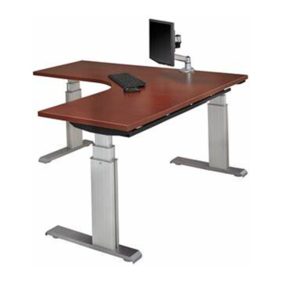
Series 4 Vuelta 3-Leg Crank Height
Adjustable Workstation Assembly Instructions
Instruction # 53552
K&A Manufacturing
6703 Zinser Street
Schofield, WI 54476
Phone: 800.298.4351
Fax: 866.882.9475
www.raproducts.com
Version Dated: 7/8/16
Read all the instructions before beginning.
Hardware Pack # 53555
Page1 OF 12
Advertisement

Subscribe to Our Youtube Channel
Related Manuals for RightAngle 4 Vuelta Series


Summary of Contents for RightAngle 4 Vuelta Series
- Page 1 K&A Manufacturing 6703 Zinser Street Schofield, WI 54476 Phone: 800.298.4351 Fax: 866.882.9475 www.raproducts.com Version Dated: 7/8/16 Series 4 Vuelta 3-Leg Crank Height Adjustable Workstation Assembly Instructions Read all the instructions before beginning. Instruction # 53552 Hardware Pack # 53555 Page1 OF 12...
- Page 2 K&A Manufacturing 6703 Zinser Street Schofield, WI 54476 Phone: 800.298.4351 Fax: 866.882.9475 www.raproducts.com The drawing below shows how to distinguish the left, center, and right leg assemblies from each other. Cage Nuts Hex Drive Hex Drive Hex Drive Hex Rod Leg C Right Leg Leg A Left Leg Leg B Center Leg...
- Page 3 Tools Required For Assembly: Power Driver W/Adjustable Torque #2 Phillips Head Driver Bit #2 Square Head Driver Bit K&A Manufacturing 3/16" Hex Head Driver Bit or Allen Wrench 6703 Zinser Street Schofield, WI 54476 Phone: 800.298.4351 Adjustable Wrench Fax: 866.882.9475 www.raproducts.com Tape Measure Level...
- Page 4 Step 1: Lay the worksurface(s) 1 on a protected surface with the pilot holes facing up. If your work- surface has a seam, lay the joiner plate 2 centered K&A Manufacturing on the seam and about 3" from the front. Attach it 6703 Zinser Street Schofield, WI 54476 Phone: 800.298.4351 with (8) wood screws 3 .
- Page 5 Step 4: Place the right leg assembly 9 on the worksurface 1 inserting the hex rod into the hex drive on the leg. You may need to turn the hex rod slightly K&A Manufacturing to align it with the hex drive. It should take less than 6703 Zinser Street Schofield, WI 54476 Phone: 800.298.4351 1/6 of a turn to accomplish this.
- Page 6 Step 6: With the help of an assistant align the cross support that is 5" shorter than the work- surface with the stickers on both leg assemblies. See below. Insert (4) socket screws 13 through the holes in the ends of the cross support and thread them into the weld nuts that are held in place by the stickers.
- Page 7 K&A Manufacturing 6703 Zinser Street Schofield, WI 54476 Phone: 800.298.4351 Fax: 866.882.9475 www.raproducts.com Step 7: Slide a weld nut 16 into the groove in the back of the cross support 12 . The projections on the weld nut must face outward. Step 8: Insert an end cap 15 into each end of the cross support 12 .
- Page 8 Step 9: Build the subassembly shown below. Slide a weld nut 16 into the groove on the front of the cross K&A Manufacturing support 20. The projections on the weld nut must face 6703 Zinser Street Schofield, WI 54476 out. Insert (2) socket screws 13 through the holes on the Phone: 800.298.4351 Fax: 866.882.9475 wide side of the L bracket 17 and thread them into the...
- Page 9 Step 13: Fully tighten the wood screws 3 attaching the leg assemblies 4, 9, and 11. K&A Manufacturing to the worksurface 1. Add (4) more wood 6703 Zinser Street Schofield, WI 54476 screws to each leg assembly. Fully tighten. Phone: 800.298.4351 Fax: 866.882.9475 www.raproducts.com Step 14: Align the holes in the u-channels 18 with the pilot holes in the worksurface 1.
- Page 10 Step 15: Slide the crank/bracket/clamp assembly 19 K&A Manufacturing onto the hex rod protruding from the front of the right 6703 Zinser Street Schofield, WI 54476 Phone: 800.298.4351 leg assembly 9. Align the holes in the bracket with Fax: 866.882.9475 www.raproducts.com the pilot holes in the worksurface 1 .
- Page 11 K&A Manufacturing 6703 Zinser Street Schofield, WI 54476 Phone: 800.298.4351 Fax: 866.882.9475 www.raproducts.com Step 16: With the help of an assistant, set the workstation upright in its final location. Level the workstation if required by turning the leveler glides clockwise (from the top) on the low corners of the unit.
- Page 12 Troubleshooting: If you have problems with the table operation, contact RightAngle™ service at 800-298-4351 or orders@raproducts.com.
Need help?
Do you have a question about the 4 Vuelta Series and is the answer not in the manual?
Questions and answers