Table of Contents
Advertisement
Quick Links
FEATURES
Fully featured evaluation board for the
►
voltage output DAC
Flexible output power supply configuration
►
Easy connection to external loads
►
Test points to monitor DAC status signals
►
ACE
evaluation software compatible
►
EVALUATION KIT CONTENTS
DC2904A-B evaluation board
►
Ribbon cable to connect to the Linduino
►
board
EQUIPMENT NEEDED
DC2026C controller board (must be purchased separately)
►
®
PC running Windows
7 or Windows 10
►
Voltmeter
►
Power supply
►
SOFTWARE NEEDED
ACE evaluation software (available for download from the
►
DC2904A
product page)
DOCUMENTS NEEDED
LTC2686 data sheet
►
DC2904A-B design files (see the DC2904A product page)
►
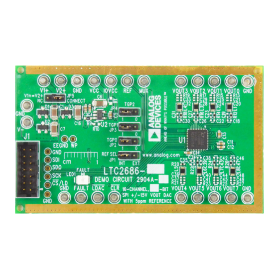
EVALUATION BOARD PHOTOGRAPH
PLEASE SEE THE LAST PAGE FOR AN IMPORTANT
WARNING AND LEGAL TERMS AND CONDITIONS.
Evaluating the LTC2686 8-Channel, 16-Bit Voltage Output SoftSpan DAC
LTC2686
multichannel
DC2026C
controller
Figure 1. DC2904A-B Evaluation Board
User Guide | DC2904A
GENERAL DESCRIPTION
The DC2904A-B is a fully featured evaluation board that is used
to evaluate the LTC2686, an 8-channel, precision voltage output
digital-to-analog converter (DAC).
The DC2904A-B is controlled through a serial peripheral interface
(SPI) from the J1 connector. The SPI signals are sent from the
DC2026C controller board through the ribbon cable that is connect-
ed to the DC2904A-B.
The DC2904A-B uses
Analysis, Control, Evaluation (ACE)
to provide an intuitive graphical user interface (GUI) that configures
and controls the LTC2686 using the SPI interface.
The LTC2686 is used for various voltage mode biasing applications
such as optical modulators for data communications. The output
voltage range for each channel is software selectable, and any
channel can be routed to the DC2904A-B MUX pin, allowing either
the channel voltage or current to be externally monitored.
For full specifications on the LTC2686, see the LTC2686 data
sheet, which must be consulted in conjunction with this user guide
when using the DC2904A-B.
UG-2018
software
Rev. 0 | 1 of 11
Advertisement
Table of Contents

Subscribe to Our Youtube Channel
Related Manuals for Analog Devices DC2904A-B


Summary of Contents for Analog Devices DC2904A-B
-
Page 1: Features
FEATURES GENERAL DESCRIPTION Fully featured evaluation board for the LTC2686 multichannel The DC2904A-B is a fully featured evaluation board that is used ► voltage output DAC to evaluate the LTC2686, an 8-channel, precision voltage output digital-to-analog converter (DAC). Flexible output power supply configuration ►... -
Page 2: Table Of Contents
User Guide DC2904A TABLE OF CONTENTS Features..............1 Reference............4 Evaluation Kit Contents......... 1 Multiplexer Output..........4 Equipment Needed..........1 On-Board Connectors........4 Software Needed...........1 Getting Started............5 Documents Needed..........1 Software Installation Procedures......5 General Description..........1 Evaluation Hardware Setup........5 Evaluation Board Photograph........1 Software Operation..........5 Evaluation Board Hardware........3 Main Window............6 Evaluation Board Overview........ -
Page 3: Evaluation Board Hardware
The DC2904A-B is powered using external supplies. The minimum requirement to power the DC2904A-B is to provide 5.0 V to 21 V on E2 (V1+) and connect E3 (GND) and E4 (V−) to ground (GND). Figure 2. DC2904A-B Hardware Connections analog.com... -
Page 4: Analog Outputs
USB port on the DC2026C. Use the LTC2686 MUX pin and can be routed to the DC2904A-B E21 the provided ribbon cable to connect J1 of the DC2904A-B to J1 connector (MUX) using the LTC2686-16 Memory Map view in the of the DC2026C. -
Page 5: Getting Started
Before connecting the DC2026C to the DC2904A-B, follow these 4. Connect the load ground to a ground (GND) turrets (either E3 steps to set up the DC2904A-B for initial use in the ACE evaluation or E23) on the DC2904A-B. software: 5. -
Page 6: Main Window
2. Type the desired hexadecimal value into the Register A (or Reference Configuration Register B) text box (see Figure The DC2904A-B uses the LTC2686 internal reference to set the Settling Offset and Gain Values full-scale range. To apply an external reference, click the box labeled Reference Select (see... - Page 7 User Guide DC2904A GETTING STARTED The default values for the dither phase (ⱷ ) and period (N) are 0° Enabling Dither Mode and N = 4. The phase and period of the dither can be modified After enabling the toggle view shown in Figure 6 as described in using the dropdown boxes to select from a fixed list of options.
- Page 8 User Guide DC2904A GETTING STARTED Figure 7. Dither View analog.com Rev. 0 | 8 of 11...
- Page 9 User Guide DC2904A GETTING STARTED Memory Map View To access the LTC2686-16 Memory Map view, click the Proceed to Memory Map button from the software main window (see Figure Figure 8. LTC2686-16 Memory Map View analog.com Rev. 0 | 9 of 11...
-
Page 10: Troubleshooting
User Guide DC2904A TROUBLESHOOTING other questions, submit them to the Precision DACs section of the HARDWARE EngineerZone site. A comprehensive list of frequently asked questions (FAQ) is availa- ™ ble on the LTC2686 FAQs page in the EngineerZone site. For analog.com Rev. -
Page 11: Ordering Information
Evaluation Board until you have read and agreed to the Agreement. Your use of the Evaluation Board shall signify your acceptance of the Agreement. This Agreement is made by and between you (“Customer”) and Analog Devices, Inc. (“ADI”), with its principal place of business at Subject to the terms and conditions of the Agreement, ADI hereby grants to Customer a free, limited, personal, temporary, non-exclusive, non-sublicensable, non-transferable license to use the Evaluation Board FOR EVALUATION PURPOSES ONLY.
Need help?
Do you have a question about the DC2904A-B and is the answer not in the manual?
Questions and answers