Advertisement
DESCRIPTION
Demonstration circuit 2911A is an IEEE 802.3bt compli-
ant and LTPoE ++ interoperable Power over Ethernet (PoE)
Powered Device (PD). It features the
controller and the
LT4321
The LT4293 provides LTPoE ++ , IEEE 802.3af (PoE,
Type 1), IEEE 802.3at (PoE + , Type 2), and IEEE 802.3bt
(PoE ++ , Type 3 and 4) compliant interfacing. It utilizes an
external, low R
(30mΩ typical) N-channel MOSFET
DS(ON)
for the Hot Swap function to improve efficiency.
Power good (PWRGD) output indicates the PD control-
ler is ready to provide power to the downstream load.
This signal can be used to enable an isolated power sup-
ply. The T2P output indicates the available power from
the Power Sourcing Equipment (PSE). This signal
PERFORMANCE SUMMARY
PARAMETER
Port Voltage (V
)
PORT
Auxiliary Voltage
Efficiency
T2P Switching Frequency
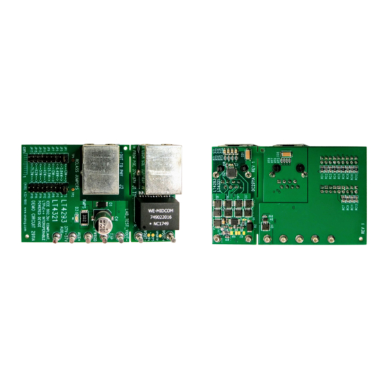
BOARD PHOTOS
Top Side
LT
4293
PD interface
®
PoE ideal diode bridge controller.
CONDITIONS
At RJ45
From AUX+ to AUX– Terminals
V
= 48V, I
PORT
Connected to an IEEE 802.3bt or LTPoE ++ PSE
That Allocates at Least 38.7W
DEMO MANUAL DC2911A
IEEE 802.3bt and LTPoE ++
Interoperable Powered Device
communicates allocated power from either LTPoE ++
or IEEE 802.3bt-compliant PSEs to the downstream
PD circuitry.
The LT4321 controls eight low R
N-channel MOSFETs to further improve end-to-end power
delivery efficiency and ease thermal design. This solution
replaces the eight diodes typically found in a passive PoE
rectifier bridge.
The DC2911A accepts up to 90W of delivered power from
a PSE via the RJ45 connector (J1) or a local 48V DC
power supply using the auxiliary supply input. When both
supplies are connected, the auxiliary supply input has
priority over the PoE input.
Design files for this circuit board are
All registered trademarks and trademarks are the property of their respective owners.
= 1.5A
OUT
LT4293, LT4321
(57mΩ typical)
DS(ON)
available.
VALUE
37V to 57V
37V to 57V
99.2% (Typical)
840Hz (Typical)
Bottom Side
Rev. 0
1
Advertisement
Table of Contents

Subscribe to Our Youtube Channel
Related Manuals for Analog Devices DC2911A


Summary of Contents for Analog Devices DC2911A
- Page 1 DS(ON) for the Hot Swap function to improve efficiency. The DC2911A accepts up to 90W of delivered power from Power good (PWRGD) output indicates the PD control- a PSE via the RJ45 connector (J1) or a local 48V DC ler is ready to provide power to the downstream load.
-
Page 2: Typical Performance Characteristics
DC2911A using a CAT5e or CAT6 Ethernet cable. and AUX– inputs of the DC2911A. (See Note.) 2. Refer to Figure 3 or Figure 4 to evaluate the DC2911A 5. After connection has been established, verify that the with a DC/DC converter. If a resistive or an active load LED (D3) is lit. - Page 3 IEEE802.3bt DC/DC CONVERTER – ENABLE PSE TYPE OPTO (TO P) DC2911A F03 Figure 3. Setup Diagram for DC2911A with a DC/DC Converter, a Microprocessor, and an IEEE 802.3bt PSE CAT5e OR CAT6 CABLE LTPoE ++ DC/DC CONVERTER – ENABLE PSE TYPE...
- Page 4 RESISTIVE OR ACTIVE LOAD DC2911A F05 Figure 5. Setup Diagram for DC2911A with a Resistive or an Active Load. Do Not Capacitively Load LAB_TEST_VOUT– Table 1. Single-Signature Classification, Power Levels and Jumper Selection PD REQUESTED POWER (AT THE PD INPUT) LTPoE ++ PD REQUESTED CLASS IEEE 802.3...
- Page 5 48V. 1. Place and connect test equipment (voltmeter, amme- ter, oscilloscope and electronic load) as shown in 4. Once the LED (D3) on the DC2911A is lit, check the Figure 6. output voltage using a voltmeter. Output voltage should be within 37V to 57V.
- Page 6 DEMO MANUAL DC2911A QUICK START PROCEDURE Table 4. Interoperability (T2P Response*, PSE Allocated Power, Number of Class/Mark Events) PSE TYPE, CLASS (POWER) IEEE 802.3 IEEE 802.3 IEEE 802.3 IEEE 802.3 LTPoE ++ TYPE 1 TYPE 2 TYPE 3 TYPE 4 AUXILIARY...
-
Page 7: Parts List
WURTH ELEKTRONIK, 60800213421 AND JP2 XFMR., 350μH, 1:1 ±2% WURTH ELEKTRONIK, 749022016 I.C., LTPoE ++ /802.3bt PD CONTROLLER, DFN10, 3mm × 3mm ANALOG DEVICES, LT4293IDD I.C., PoE IDEAL DIODE BRIDGE CONTROLLER, QFN16-UF , ANALOG DEVICES, LT4321IUF 4mm × 4mm STENCILS, (TOP & BOTTOM) STENCIL DC2911A-1 Rev. - Page 8 DEMO MANUAL DC2911A SCHEMATIC DIAGRAM Rev. 0...
-
Page 9: Schematic Diagram
Devices for its use, nor for any infringements of patents or other rights of third parties that may result from its use. Specifications subject to change without notice. No license is granted by implication or otherwise under any patent or patent rights of Analog Devices. - Page 10 Board until you have read and agreed to the Agreement. Your use of the Evaluation Board shall signify your acceptance of the Agreement. This Agreement is made by and between you (“Customer”) and Analog Devices, Inc. (“ADI”), with its principal place of business at One Technology Way, Norwood, MA 02062, USA. Subject to the terms and conditions of the Agreement, ADI hereby grants to Customer a free, limited, personal, temporary, non-exclusive, non-sublicensable, non-transferable license to use the Evaluation Board FOR EVALUATION PURPOSES ONLY.
Need help?
Do you have a question about the DC2911A and is the answer not in the manual?
Questions and answers