Advertisement
Quick Links
DESCRIPTION
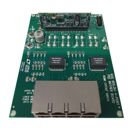
Demonstration circuit 2685B is a 4-port IEEE 802.3bt
power sourcing equipment (PSE) composed of a
DC2684A-B (daughter card) and DC2683A (mother-
board). The DC2685B (kit) is used for evaluation of
the
LTC
4291-1/LTC4292
®
IEEE 802.3af, IEEE 802.3at, or IEEE 802.3bt powered
devices (PDs) can be connected and powered from this
BOARD PHOTO
PSE chipset. Up to four
DEMO MANUAL DC2685B
DC2683A and DC2684A-B
LTC4291-1/LTC4292
4-Port IEEE 802.3bt PSE
system using a single power supply. A DC590 is con-
nected to the DC2685B for I
This demonstration manual provides a quick start proce-
dure, a DC2684A-B daughter card overview, a DC2683A
mother board overview, schematics, and layout printouts.
Design files for this circuit board are available.
All registered trademarks and trademarks are the property of their respective owners.
2
C interfacing with QuikEval™.
Rev A
1
Advertisement

Subscribe to Our Youtube Channel
Related Manuals for Analog Devices LINEAR DC2683A


Summary of Contents for Analog Devices LINEAR DC2683A
- Page 1 DEMO MANUAL DC2685B DC2683A and DC2684A-B LTC4291-1/LTC4292 4-Port IEEE 802.3bt PSE DESCRIPTION Demonstration circuit 2685B is a 4-port IEEE 802.3bt system using a single power supply. A DC590 is con- power sourcing equipment (PSE) composed of a nected to the DC2685B for I C interfacing with QuikEval™.
- Page 2 DEMO MANUAL DC2685B QUICK START PROCEDURE Follow the quick start procedure below for basic operation sourcing the maximum delivered power for all four of the DC2685B kit. Refer to Figure 1 through Figure 3 ports set by JP3 and JP4 on the daughter card (or and Table 1 through Table 4 for proper equipment setup.
-
Page 3: Quick Start Procedure
DEMO MANUAL DC2685B QUICK START PROCEDURE Figure 1. DC2684A-B Jumpers: AUTO, 4PV#, PM0 and PM1 Figure 2. Inserting the DC2684A-B Daughter Card Into J7 of the DC2683A Motherboard Rev A... - Page 4 DEMO MANUAL DC2685B QUICK START PROCEDURE Table 1. DC2684A-B AUTO and 4PV# Jumper Settings Table 3. DC2685B Power Supply Voltage Range per PSE Type JUMPER SETTING OPERATION IEEE TYPE Supply Voltage Range AUTO (JP1) Host Control Required Type 3 51V to 57V Autonomous Type 4 53V to 57V...
- Page 5 DEMO MANUAL DC2685B DEMONSTRATION CIRCUIT 2684A-B DAUGHTER CARD Demonstration circuit 2684A-B is an IEEE 802.3bt 8-chan- LTC4292 data sheet. The DC2684A-B demonstrates nel PSE daughter card that features the LTC4291-1/ proper LTC4291-1/LTC4292 board layout on a compact LTC4292 chipset. This daughter card mates with a 4-Port, daughter card approximately the height and width of a 2 4-Pair PoE motherboard for use in IEEE 802.3bt Type 3 or ×...
- Page 6 DEMO MANUAL DC2685B DEMONSTRATION CIRCUIT 2684A-B DAUGHTER CARD I/O LED Indicators The DC2684A-B features two LEDs to indicate the states SDAOUT SDAOUT of the LTC4291-1/LTC4292 general purpose input/output SDAIN SDAIN pins GP0 and GP1. These pins are configured as inputs or outputs via I C.
-
Page 7: Demonstration Circuit 2683A Mother Board
DEMO MANUAL DC2685B DEMONSTRATION CIRCUIT 2683A MOTHER BOARD capacitance components; these components must be Each pairset channel (2 per port) has a respective OUTnM sized to the final system requirements. LED to indicate if the channel is powered on with PoE. Demonstration circuit 2683A is a 4-Port, 2-channels per The INT LED (D6) indicates if the interrupt line is pulled port IEEE 802.3bt PoE PSE motherboard. - Page 8 DEMO MANUAL DC2685B SUPPLEMENTARY Table 5. DC590 Jumper Selection. Refer to the DC590 Demo Manual for Further Details. JUMPER SETTING OPERATION PROG Microcontroller in-circuit programming header. Do NOT install jumper; make no connections. MODE Do NOT install jumper; make no connections. Watchdog Enables Do NOT install jumper;...
- Page 9 DEMO MANUAL DC2685B DC2684A-B DAUGHTER CARD LAYOUT FILES Figure 7. DC2684A-B Top Silkscreen Figure 8. DC2684A-B Top Layer Rev A...
- Page 10 DEMO MANUAL DC2685B DC2684A-B DAUGHTER CARD LAYOUT FILES Figure 9. DC2684A-B Inner Layer 2 Figure 10. DC2684A-B Inner Layer 3 Rev A...
- Page 11 DEMO MANUAL DC2685B DC2684A-B DAUGHTER CARD LAYOUT FILES Figure 11. DC2684A-B Bottom Layer Figure 12. DC2684A-B Bottom Silkscreen Rev A...
- Page 12 DEMO MANUAL DC2685B DC2683A MOTHER BOARD LAYOUT FILES Figure 13. DC2683A Top Silkscreen Rev A...
-
Page 13: Dc2683A Mother Board Layout Files
DEMO MANUAL DC2685B DC2683A MOTHER BOARD LAYOUT FILES Figure 14. DC2683A Top Layer Rev A... - Page 14 DEMO MANUAL DC2685B DC2683A MOTHER BOARD LAYOUT FILES Figure 15. DC2683A Inner Layer 2 Rev A...
- Page 15 DEMO MANUAL DC2685B DC2683A MOTHER BOARD LAYOUT FILES Figure 16. DC2683A Inner Layer 3 Rev A...
- Page 16 DEMO MANUAL DC2685B DC2683A MOTHER BOARD LAYOUT FILES Figure 17. DC2683A Bottom Layer Rev A...
- Page 17 DEMO MANUAL DC2685B DC2683A MOTHER BOARD LAYOUT FILES Figure 18. DC2683A Bottom Silkscreen Rev A...
- Page 18 DEMO MANUAL DC2685B DC2684A-B DAUGHTER CARD SCHEMATIC Rev A...
- Page 19 DEMO MANUAL DC2685B DC2684A-B DAUGHTER CARD SCHEMATIC Rev A...
- Page 20 DEMO MANUAL DC2685B DC2683A MOTHERBOARD SCHEMATIC Rev A...
-
Page 21: Dc2683A Motherboard Schematic
Devices for its use, nor for any infringements of patents or other rights of third parties that may result from its use. Specifications subject to change without notice. No license is granted by implication or otherwise under any patent or patent rights of Analog Devices. - Page 22 Board until you have read and agreed to the Agreement. Your use of the Evaluation Board shall signify your acceptance of the Agreement. This Agreement is made by and between you (“Customer”) and Analog Devices, Inc. (“ADI”), with its principal place of business at One Technology Way, Norwood, MA 02062, USA. Subject to the terms and conditions of the Agreement, ADI hereby grants to Customer a free, limited, personal, temporary, non-exclusive, non-sublicensable, non-transferable license to use the Evaluation Board FOR EVALUATION PURPOSES ONLY.
Need help?
Do you have a question about the LINEAR DC2683A and is the answer not in the manual?
Questions and answers