Table of Contents
Advertisement
Quick Links
DESCRIPTION
Demonstration circuit 2973A shows the
Primary Battery State of Health (SOH) monitor with pre-
cision coulomb counter operating with a configurable
peak current limit. The LTC3337 supports input voltages
from 1.8V to 5.5V and a peak current up to 100mA with a
quiescent current of 100nA. Coulomb count, battery volt-
age, and Battery Series Resistance (BSR) are measurable
and can be used to quantify the charge state and health
of a battery.
PERFORMANCE SUMMARY
SYMBOL
PARAMETER
V
Input Voltage Range
IN
I
Output Current
OUT
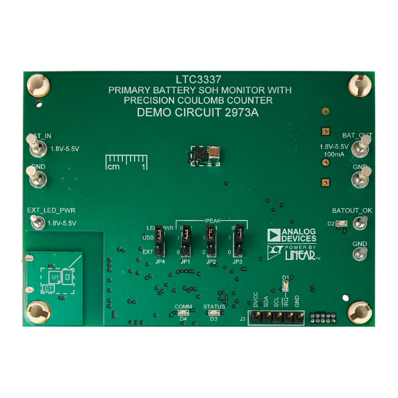
BOARD PHOTO
DEMO MANUAL DC2973A
Primary Battery SOH Monitor with
Precision Coulomb Counter
LTC
3337
The DC2973A demonstrates a simple layout for the high-
®
est-power configuration of the LTC3337. The circuit can
be reduced for lower I
be connected directly to a PC using a micro USB cable in
order to run a GUI and configure simple a Battery State of
Charge (SOC) monitor. Source code for the GUI is avail-
able and can be used as a starting point for LTC3337
firmware development.
Design files for this circuit board are
All registered trademarks and trademarks are the property of their respective owners.
Specifications are at T
= 25°C
A
CONDITIONS
IPK2 – IPK0 = 111
LTC3337
levels. The demo board can
PEAK
available.
MIN
TYP
MAX
1.8
5.5
100
UNITS
V
mA
Rev. 0
1
Advertisement
Table of Contents

Related Manuals for Analog Devices DC2973A


Summary of Contents for Analog Devices DC2973A
- Page 1 Precision Coulomb Counter DESCRIPTION Demonstration circuit 2973A shows the 3337 The DC2973A demonstrates a simple layout for the high- ® Primary Battery State of Health (SOH) monitor with pre- est-power configuration of the LTC3337. The circuit can cision coulomb counter operating with a configurable be reduced for lower I levels.
-
Page 2: Quick Start Procedure
Or use an electronic load in CC mode pulling I PEAK 6. Once familiar with the operation, replace PS1 and R1 2. Connect DC2973A to a computer using a USB cable and with your battery and system load, respectively. launch QuikEval™ to download and run the GUI (see GUI Application section for download instructions). -
Page 3: Software Tools
Note that the IPEAK setting is locked at IPK2 IPK1 IPK0 IPEAK startup. Refer to Table 1 to configure the IPEAK setting. This 10mA table is also located on the back of the DC2973A PCB. 15mA 20mA 25mA 50mA 75mA 100mA SOFTWARE TOOLS... - Page 4 LTC3337. In addition, it pro- tab just displays the schematic for reference. vides an advanced debugging interface that can be used in evaluating operation of the DC2973A as well as a cus- Dashboard Tab tomer’s own design.
-
Page 5: Gui Application
DEMO MANUAL DC2973A GUI APPLICATION Engineering Tab For detailed information about a register, hovering over it for about a second will display the same tool tips as are The Engineering tab is an advanced debugging tool which visible in the other tabs of the GUI. - Page 6 DEMO MANUAL DC2973A GUI APPLICATION Schematic Tab The Schematic Tab simply shows the DC2973A schematic for quick reference while using the GUI. Figure 4. The Schematic Tab Rev. 0...
- Page 7 DEMO MANUAL DC2973A GUI APPLICATION Logger Window collection. Data can be exported into a CSV format (for import to Excel) or to a SQL database. Note that other GUI The Logger can be launched by going to Window ➝ tabs will be inactive while logging, so writing bitfields is Show Logger.
- Page 8 XSTR., MOSFET, DUAL, N-CH, 280mA, SOT-563 DIODES INC., 2N7002VAC-7 MH1, MH2, MH3, MH4 STANDOFF , NYLON, SNAP-ON, 0.50" KEYSTONE, 8833 PCB1 PCB, DC2973A ADI APPROVED SUPPLIER, 600-DC2973A R1, R2, R6 RES., 10k, 5%, 1/16W, 0402, AEC-Q200 NIC, NRC04J103TRF ROHM, MCR01MZPJ103 VISHAY, CRCW040210K0JNED RES., OPTION, 0603...
-
Page 9: Parts List
DEMO MANUAL DC2973A PARTS LIST ITEM QTY REFERENCE PART DESCRIPTION MANUFACTURER/PART NUMBER R8, R13, R14 RES., 2.2k, 5%, 1/16W, 0402, AEC-Q200 VISHAY, CRCW04022K20JNED NIC, NRC04J222TRF R9, R10, R11 RES., 301Ω, 1%, 1/10W, 0603, AEC-Q200 PANASONIC, ERJ3EKF3010V VISHAY, CRCW0603301RFKEA NIC, NRC06F3010TRF RES., 10k, 5%, 1/16W, 0402... - Page 10 DEMO MANUAL DC2973A SCHEMATIC DIAGRAM Rev. 0...
-
Page 11: Schematic Diagram
Devices for its use, nor for any infringements of patents or other rights of third parties that may result from its use. Specifications subject to change without notice. No license is granted by implication or otherwise under any patent or patent rights of Analog Devices. - Page 12 Board until you have read and agreed to the Agreement. Your use of the Evaluation Board shall signify your acceptance of the Agreement. This Agreement is made by and between you (“Customer”) and Analog Devices, Inc. (“ADI”), with its principal place of business at One Technology Way, Norwood, MA 02062, USA. Subject to the terms and conditions of the Agreement, ADI hereby grants to Customer a free, limited, personal, temporary, non-exclusive, non-sublicensable, non-transferable license to use the Evaluation Board FOR EVALUATION PURPOSES ONLY.
- Page 13 Mouser Electronics Authorized Distributor Click to View Pricing, Inventory, Delivery & Lifecycle Information: Analog Devices Inc. DC2973A...
Need help?
Do you have a question about the DC2973A and is the answer not in the manual?
Questions and answers