Advertisement
Quick Links
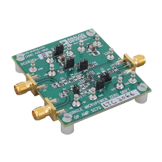
DESCRIPTION
Demonstration circuit 2837A is a customizable
board showcasing the micropower zero-drift op amp
LTC
2063 (-A option) or
®
down in an SC70 6-pin package. The board is laid out for
most common op amp applications and left mostly unstuffed
to maximize flexibility for a wide range of applications.
The DC2837A includes the SC70 package op amp, jump-
ers, unity gain configuration resistors, input lowpass fil-
ters, reverse supply protection, and supply bypass capaci-
tors on a small printed circuit board with turrets and SMA
PERFORMANCE SUMMARY
SYMBOL
PARAMETER
LTC2063, V
= 5V
S
V
Input Offset Voltage
OS
ΔV
/Δ
Input Offset Voltage Drift
OS
T
I
Input Bias Current
B
GBW
Gain Bandwidth Product
f
Internal Chopping Frequency
C
I
Supply Current
S
LTC2066, V
= 5V
S
V
Input Offset Voltage
OS
ΔV
/Δ
Input Offset Voltage Drift
OS
T
I
Input Bias Current
B
GBW
Gain Bandwidth Product
f
Internal Chopping Frequency
C
IS
Supply Current
2µA/10µA Supply Current, Low I
Zero-Drift Operational Amplifiers
LTC2066
(-B option) with shut-
Specifications are at T
CONDITIONS
V
= 5.25V
S
–40°C to 85°C
R
= 499kΩ
L
No Load
In Shutdown (SHDN = V
V
= 5.25V
S
–40°C to 85°C
R
= 499kΩ
L
No load
In Shutdown (SHDN = V
DEMO MANUAL
DC2837A-A/DC2837A-B
LTC2063/LTC2066
connectors for input, output, power and shutdown. The
board may be used in split rail or single supply as desired.
The user only needs to furnish external ±2.5V split sup-
plies and an input signal to operate the board. An external
shutdown signal can be applied as well to demonstrate
the very minimal transient current when starting up the
part from shutdown.
Design files for this circuit board are
All registered trademarks and trademarks are the property of their respective owners.
= 25°C
A
MIN
–
)
–
)
available.
TYP
MAX
UNITS
1
±5
±0.02
µV/°C
–3
±20
20
5
1.4
2
90
170
1
±5
±0.02
µV/°C
±5
±35
100
25
7.5
10
90
170
1
,
B
µV
pA
kHz
kHz
µA
nA
µV
pA
kHz
kHz
µA
nA
Rev. 0
Advertisement

Related Manuals for Analog Devices DC2837A-A


Summary of Contents for Analog Devices DC2837A-A
- Page 1 DEMO MANUAL DC2837A-A/DC2837A-B LTC2063/LTC2066 2µA/10µA Supply Current, Low I Zero-Drift Operational Amplifiers DESCRIPTION Demonstration circuit 2837A is a customizable connectors for input, output, power and shutdown. The board showcasing the micropower zero-drift op amp board may be used in split rail or single supply as desired.
-
Page 2: Quick Start Procedure
3rd Position GND for Note: The input lowpass filter at IN has a cutoff – (Single-Supply) and GND Jumper Storage when of 480Hz for DC2837A-A (LTC2063) and 2.4kHz (Split Rail) Using Split Rails for DC2837A-B (LTC2066). Add Z2 in Short Out R6 Default Open Path Parallel with R5... - Page 3 DEMO MANUAL DC2837A-A/DC2837A-B QUICK START PROCEDURE SPLIT SINGLE 10µF 10µF DC BIAS – SINGLE OR SPLIT SUPPLY FEEDBACK – –IN 49.9 – 0.1µF 33nF/ 6.8nF INPUT FILTER – – DC BIAS SHDN/ENABLE DC2837A-B F01 Figure 1. Simplified Generic Schematic DC2837A-B F02 Figure 2.
-
Page 4: Operating Principles
DEMO MANUAL DC2837A-A/DC2837A-B OPERATING PRINCIPLES DEFAULT: UNITY GAIN WITH INPUT FILTER The DC2837A board provides multiple empty mostly-0805 component footprints for users to configure the LTC2063/ The default configuration of the board is for unity gain LTC2066 as desired. Common configurations and func- with split supplies, as shown in Figure 3. - Page 5 DEMO MANUAL DC2837A-A/DC2837A-B OPERATING PRINCIPLES ADDING DC BIASES R4 may be optionally populated with a resistor equivalent to R for increased precision over temperature. R4 To add a DC bias using a resistor divider, populate Z1 and will cancel out I...
-
Page 6: Design Example
DEMO MANUAL DC2837A-A/DC2837A-B OPERATING PRINCIPLES Negative offsets may also be applied by shifting JP1 and DESIGN EXAMPLE – JP3 to tie to V , and populating R10 instead of R9 with Figure 7 shows a general textbook second-order active the desired R lowpass filter, which may be either a Bessel or Butterworth filter depending on the choice of component values. - Page 7 –3dB 5. Replace R5 with desired capacitor C2 value DC2837A-A or DC2837A. The target specifications for 6. Stuff Z1 with desired value (gain set resistor). both a Bessel and a Butterworth filter with this architec- ture are provided in Table 2.
- Page 8 Board until you have read and agreed to the Agreement. Your use of the Evaluation Board shall signify your acceptance of the Agreement. This Agreement is made by and between you (“Customer”) and Analog Devices, Inc. (“ADI”), with its principal place of business at One Technology Way, Norwood, MA 02062, USA. Subject to the terms and conditions of the Agreement, ADI hereby grants to Customer a free, limited, personal, temporary, non-exclusive, non-sublicensable, non-transferable license to use the Evaluation Board FOR EVALUATION PURPOSES ONLY.
Need help?
Do you have a question about the DC2837A-A and is the answer not in the manual?
Questions and answers