Advertisement
Quick Links
DESCRIPTION
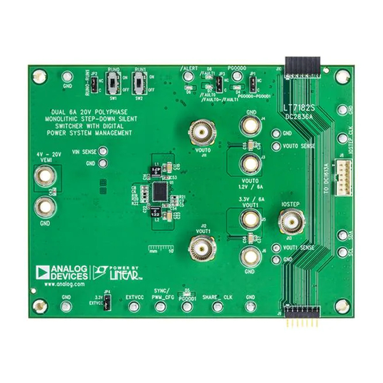
Demonstration Circuit 2836A is a dual-output PolyPhase
DC/DC synchronous step-down regulator with 4V to 20V
input range featuring
LT
ply 6A continuous/9A maximum transient load current.
LT7182S is a dual 6A monolithic step-down regulator.
The second-generation Silent Switcher
incorporated into LT7182S to minimize EMI and reduce
PCB layout sensitivity. It also integrates digital power sys-
tem management function allowing for programmability
and telemetry with a PMBus/I
face. Please see LT7182S data sheet for more detailed
information.
The demonstration circuit 2836A runs at 1MHz to mini-
mize solution size. The peak efficiency at 12V input is
83.2% for 1.2V rail and 91.1% for 3.3V rail. The IC tem-
perature rise is 70°C when both channels run at full load,
6A each, at 1MHz.
The demo board has EMI filters installed for both chan-
nels. The conducted and radiated EMI performances of
the board (with EMI filters) are shown in Figure 2. The red
lines in Figure 2 are CISPR25 CLASS 5 limit.
PERFORMANCE SUMMARY
SYMBOL
PARAMETER
V
Input Voltage Range
IN
V
Output0 Voltage
OUT0
I
Maximum Output0 Current
OUT0
V
Output1 Voltage
OUT1
I
Maximum Output1 Current
OUT1
f
Switching Frequency
SW
EFE
Efficiency at DC
Dual Channel 6A, 20V, PolyPhase
Step-Down Silent Switcher with Digital
7182S. Each output can sup-
®
structure is
®
2
C compliant serial inter-
Specifications are at T
CONDITIONS
V
IN
V
IN
DEMO MANUAL DC2836A
Power System Management
DC2836A powers up to default settings and produces
®
power based on configuration resistors without the need
for any serial bus communication. This allows easy evalu-
ation of the DC/DC converter. To fully explore the power
system management features of the part, download the
GUI software LTpowerPlay
2
I
C/SMBus/PMBus dongle DC1613A to connect to the
board. LTpowerPlay allows the user to reconfigure the part
on the fly and store the configuration in EEPROM, view
telemetry of voltage, current, temperature and fault status.
GUI Download
The software can be downloaded from:
The LT7182S data sheet gives a complete description of
the part, operation and application information. The data
sheet must be read in conjunction with this demo manual
for DC2836A.
For more details and instructions of LTpowerPlay, please
refer to LTpowerPlay GUI for LT7182S Quick Start Guide.
Design files for this circuit board are
All registered trademarks and trademarks are the property of their respective owners.
= 25°C
A
= 12V, I
= 3A, I
= 0A
OUT0
OUT1
= 12V, I
= 3A, I
= 0A
OUT1
OUT0
LT7182S
onto your PC and use ADI's
®
LTpowerPlay
available.
MIN
TYP
MAX
4
20
1.2
9
3.3
9
0.925
1
1.075
83.2
91.1
UNITS
V
V
A
V
A
MHz
%
%
Rev. 0
1
Advertisement

Subscribe to Our Youtube Channel
Related Manuals for Analog Devices DC2836A


Summary of Contents for Analog Devices DC2836A
- Page 1 Step-Down Silent Switcher with Digital Power System Management DESCRIPTION Demonstration Circuit 2836A is a dual-output PolyPhase DC2836A powers up to default settings and produces ® DC/DC synchronous step-down regulator with 4V to 20V power based on configuration resistors without the need input range featuring 7182S.
- Page 2 DEMO MANUAL DC2836A QUICK START PROCEDURE DC2836A is easy to set up to evaluate the performance of a. If efficiency measurements are desired, ammeters the LT7182S. Refer to Figure 3 for proper measurement can be put in series with the output loads to measure equipment setup and follow the procedure below: the DC2836A’s output currents.
-
Page 3: Quick Start Procedure
DEMO MANUAL DC2836A QUICK START PROCEDURE Conducted EMI Performance (CISPR25 Conducted Emission Test with Class 5 Peak Limits) CLASS 5 PEAK LIMIT –10 CONDUCTED PEAK MAX –20 100k FREQUENCY (kHz) dc2836a F02a DC2836A DEMO BOARD (WITH EMI FILTER INSTALLED) 14V INPUT TO 1.2V OUTPUT0 PLUS 3.3V OUTPUT1 AT 6A... - Page 4 DEMO MANUAL DC2836A QUICK START PROCEDURE Figure 3. Proper Measurement Equipment Setup Rev. 0...
-
Page 5: Usb Cable
QUICK START PROCEDURE INPUT OR OUTPUT CAPACITOR Figure 4. Measuring Input or Output Ripple Connecting a PC to DC2836A margin set points, OV/UV limits, temperature fault limits, sequencing parameters, the fault log, fault responses, You can use a PC to reconfigure the power manage- GPIOs and other functionalities. - Page 6 DEMO MANUAL DC2836A LTpowerPlay SOFTWARE GUI LTpowerPlay is a powerful Windows based development power issues when bringing up rails. LTpowerPlay utilizes environment that supports Linear Technology power sys- the DC1613A USB-to-SMBus controller to communicate tem management ICs and μModules. The software sup- with one of many potential demo system, or a customer ports a variety of different tasks.
- Page 7 1. Download and install the LTPowerPlay GUI: LTpowerPlay | Analog Devices 2. Launch the LTpowerPlay GUI. a. The GUI should automatically identify the DC2836A. The system tree on the left hand side should look like this: Then, click the W (PC to RAM) icon to write these reg- ister values to the LT7182S.
- Page 8 DEMO MANUAL DC2836A PARTS LIST ITEM REFERENCE PART DESCRIPTION MANUFACTURER/PART NUMBER Required Circuit Components C5, C6, C8 CAP ., 10µF, X6S, 10V, 10%, 0603 MURATA, ZRB18AC81A106KE01L CAP ., 1µF, X7R, 16V, 10%, 0603 MURATA, GRM188R71C105KA12D C14, C22 CAP ., 0.1µF, X7R, 25V, 10%, 0402...
-
Page 9: Parts List
DEMO MANUAL DC2836A PARTS LIST ITEM REFERENCE PART DESCRIPTION MANUFACTURER/PART NUMBER R1, R11, R12, R14, R16, R18, R23, R25, RES., 0Ω, 1/10W, 0603 VISHAY, CRCW06030000Z0EA R35, R38, R41 R5, R6, R37, R39, R56 RES., 10k, 1%, 1/10W, 0603 VISHAY, CRCW060310K0FKEA R13, R15, R22, R24, R26, R27, R28, RES., OPTION, 0603... - Page 10 DEMO MANUAL DC2836A SCHEMATIC DIAGRAM Rev. 0...
-
Page 11: Schematic Diagram
Devices for its use, nor for any infringements of patents or other rights of third parties that may result from its use. Specifications subject to change without notice. No license is granted by implication or otherwise under any patent or patent rights of Analog Devices. - Page 12 Board until you have read and agreed to the Agreement. Your use of the Evaluation Board shall signify your acceptance of the Agreement. This Agreement is made by and between you (“Customer”) and Analog Devices, Inc. (“ADI”), with its principal place of business at One Technology Way, Norwood, MA 02062, USA. Subject to the terms and conditions of the Agreement, ADI hereby grants to Customer a free, limited, personal, temporary, non-exclusive, non-sublicensable, non-transferable license to use the Evaluation Board FOR EVALUATION PURPOSES ONLY.
Need help?
Do you have a question about the DC2836A and is the answer not in the manual?
Questions and answers