Table of Contents
Advertisement
Quick Links
One Technology Way • P.O. Box 9106 • Norwood, MA 02062-9106, U.S.A. • Tel: 781.329.4700 • Fax: 781.461.3113 • www.analog.com
Evaluating the LTC2672 Five-Channel, Low Dropout, 300 mA, Current Source Output,
FEATURES
Fully featured evaluation board for the LTC2672
QuikEval evaluation software compatible
Sample Arduino code compatible (available on the
Linduino
web page)
EVALUATION KIT CONTENTS
DC2903A evaluation board
Ribbon cable to connect to the Linduino DC2026C
EQUIPMENT NEEDED
DC2026C controller board (must be purchased separately)
PC running Windows® 7 or Windows 10
Current meter
SOFTWARE NEEDED
QuikEval evaluation software (available for download from
the DC2903A product page)
DOCUMENTS NEEDED
LTC2672 data sheet
DC2903A design files (see the DC2903A product page)
PLEASE SEE THE LAST PAGE FOR AN IMPORTANT
WARNING AND LEGAL TERMS AND CONDITIONS.
16-Bit SoftSpan DAC
GENERAL DESCRIPTION
The DC2903A is a fully featured evaluation board that
evaluates the LTC2672, a five-channel, 16-bit, current source
output digital-to-analog converter (DAC).
The DC2903A is controlled through a serial peripheral
interface (SPI) from the J1 connector. The SPI signals are sent
from the
that is connected to the DC2903A.
The DC2903A uses QuikEval evaluation software to provide an
intuitive graphical user interface (GUI) that configures and
controls the LTC2672 using the SPI interface.
The LTC2672 is used for various current mode biasing
applications such as tunable lasers or resistive heaters. The
output current ranges are software selectable, and each channel
is routed to the DC2903A MUX pin for external monitoring.
For full specifications on the LTC2672, see the LTC2672 data
sheet, which must be consulted in conjunction with this user
guide when using the DC2903A.
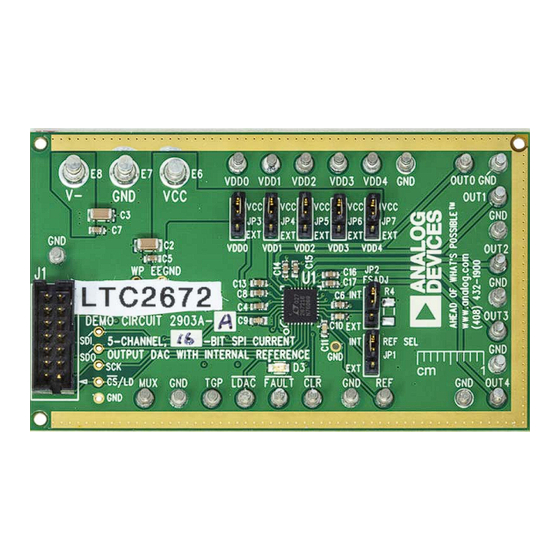
EVALUATION BOARD PHOTOGRAPH
Figure 1. DC2903A Evaluation Board
Rev. 0 | Page 1 of 13
DC2903A
DC2026C
controller board through the ribbon cable
User Guide
UG-1901
Advertisement
Table of Contents

Related Manuals for Analog Devices DC2903A


Summary of Contents for Analog Devices DC2903A
-
Page 1: Features
The SOFTWARE NEEDED output current ranges are software selectable, and each channel is routed to the DC2903A MUX pin for external monitoring. QuikEval evaluation software (available for download from the DC2903A product page) -
Page 2: Table Of Contents
UG-1901 DC2903A User Guide TABLE OF CONTENTS Features ....................1 On-Board Connectors ..............4 Evaluation Kit Contents ..............1 Getting Started ...................5 Equipment Needed ................1 Software Installation Procedures ..........5 Software Needed ................1 Evaluation Hardware Setup ............5... -
Page 3: Evaluation Board Hardware
The DC2903A is powered using external supplies. The minimum to the DC2026C controller board shown in Figure 2. The requirement to power the DC2903A is to provide 2.1 V to 5.5 V on ribbon cable provided in the evaluation kit connects the E6 (VCC) and connect E7 (GND) and E8 (V−) to ground (GND). -
Page 4: Analog Outputs
(MUX). Refer to the LTC2672 data sheet for more evaluation software through the SPI. Use the provided ribbon details on the multiplexer functionality. cable to connect J1 of the DC2903A to J1 of the DC2026C. When this connection is made, the DC2026C powers the electrically PRECISON R... -
Page 5: Getting Started
(see Figure 4) until the software recognizes the DC2903A. Before connecting the DC2026C to the DC2903A, take the When the software recognizes the DC2903A, the main software following steps to set up the DC2903A for initial use in the window in Figure 5 opens. QuikEval evaluation software:... -
Page 6: Main Window
Write & Update in the individual channel block of the GUI. the full-scale range. If a different resistor is manually populated on R4 of the DC2903A, the resistor value can be changed in the For example, in Figure 6, a current of 100 mA is assigned on R_FSADJ (KΩ) text box (see Figure 5). -
Page 7: Using The Software
LTC2672. (see Figure 7). Normal view allows the user to change most On the DC2903A, the monitor multiplexer output is available settings on the LTC2672 and the settings of each channel with at the MUX turret. - Page 8 UG-1901 DC2903A User Guide Span Power Down DAC Select an option from the Span dropdown list to send a write Click Power Down DAC to power down the channel. The span of DAC n command to the LTC2672. Channel x box title darkens and the title changes to indicate that the channel is powered down.
-
Page 9: Toggle View
DC2903A User Guide UG-1901 TOGGLE VIEW Switching the bit (or TGP pin) results in the following outcomes. First, the source for the DAC output register changes. If the bit The QuikEval evaluation software allows the user to switch the LTC2672 outputs by selecting the Toggle View tab (see Figure 8). -
Page 10: Controls For The Ltc2672 Toggle Functionality
UG-1901 DC2903A User Guide CONTROLS FOR THE LTC2672 TOGGLE FUNCTION Click the Auto Toggle button to change which register feeds the DAC output register and to update the DAC output The LTC2672 has a double buffered output register system that register. -
Page 11: Troubleshooting
DC2903A User Guide UG-1901 TROUBLESHOOTING HARDWARE A comprehensive list of frequently asked questions (FAQ) is available on the LTC2672: FAQ page in the EngineeringZone site. For other questions, please submit them to the precision DACs section of the EngineeringZone site. -
Page 12: Evaluation Board Schematic
UG-1901 DC2903A User Guide EVALUATION BOARD SCHEMATIC Figure 9. DC2903A Schematic Rev. 0 | Page 12 of 13... -
Page 13: Ordering Information
By using the evaluation board discussed herein (together with any tools, components documentation or support materials, the “Evaluation Board”), you are agreeing to be bound by the terms and conditions set forth below (“Agreement”) unless you have purchased the Evaluation Board, in which case the Analog Devices Standard Terms and Conditions of Sale shall govern. Do not use the Evaluation Board until you have read and agreed to the Agreement.
Need help?
Do you have a question about the DC2903A and is the answer not in the manual?
Questions and answers