Advertisement
Quick Links
Description
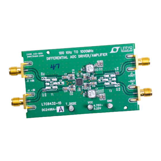
Demonstration circuit 2496A features the LTC6432-15
differential ADC Driver/IF Amplifier. The
a fixed power gain of 15.9dB and works from 100kHz
to 1400MHz. It is part of the high linearity LTC643X-YY
amplifier series.
As a differential amplifier, the LTC6432-15 offers flat gain
and impressive linearity from 100kHz to 1GHz using a
single output bias network. Since high fidelity differen-
tial test equipment is lacking, the DC2496A offers single
100kHz to 1000MHz Differential
ADC Driver/IF/RF Amplifier
ended inputs and outputs so that the LTC6432-15 perfor-
LTC
6432-15
has
mance may be evaluated with standard test equipment.
®
The native LTC6432-15 has 100Ω differential source and
load impedances, so the demo circuit uses 2:1 transform-
ers to convert the differential input/output impedances to
50Ω single-ended impedance.
Design files for this circuit board are available at
http://www.linear.com/demo/DC2496A-A
L, LT, LTC, LTM, Linear Technology and the Linear logo are registered trademarks of Analog
Devices, Inc. All other trademarks are the property of their respective owners.
DEMO MANUAL
DC2496A-A/DC2496A-B
LTC6432-15
dc2496aaf
1
Advertisement

Related Manuals for Analog Devices LINEAR DC2496A-A


Summary of Contents for Analog Devices LINEAR DC2496A-A
- Page 1 DEMO MANUAL DC2496A-A/DC2496A-B LTC6432-15 100kHz to 1000MHz Differential ADC Driver/IF/RF Amplifier Description Demonstration circuit 2496A features the LTC6432-15 ended inputs and outputs so that the LTC6432-15 perfor- differential ADC Driver/IF Amplifier. The 6432-15 mance may be evaluated with standard test equipment. ®...
-
Page 2: Operation
DEMO MANUAL DC2496A-A/DC2496A-B operation Demo Circuit 2496A is a high linearity, fixed gain amplifier. operation. The V pull-up networks (L1, L2, L3, L4, R1, It is designed for ease of use. The LTC6432-15 is inter- R5, R9 and R13) and the de-coupling capacitors (C2, C3, nally matched to 100Ω... - Page 3 DEMO MANUAL DC2496A-A/DC2496A-B operation dc2496aaf...
- Page 4 DEMO MANUAL DC2496A-A/DC2496A-B operation dc2496aaf...
- Page 5 DEMO MANUAL DC2496A-A/DC2496A-B operation Figure 3 and Figure 4 show the two port DC2496A-A’s and and Figure 6 show demo boards’ typical linearity, noise DC2496A-B’s S-Parameters performances, and Figure 5 figures and gain performances. –5 –5 –10 –10 –15 –15 –20 –20 –25 –25 –30 –30 –35...
- Page 6 DEMO MANUAL DC2496A-A/DC2496A-B operation Setup Signal Sources and Spectrum Analyzer e. The attenuator pads on all three ports of the signal combiner will further support isolation of the two input The LTC6432-15 is an amplifier with high linearity per- signal sources. They also reduce reflections and promote formance.
-
Page 7: Quick Start Procedure
DEMO MANUAL DC2496A-A/DC2496A-B Quick start proceDure Demo Circuit 2496A-A can be set up to evaluate the per- are 4.8MHz and 5.4MHz, respectively. The _HIGH formance of the LTC6432-15. Refer to Figure 7 for proper measurement levels should be approximately –102dBc; equipment connections and follow the procedure below: + 53dBm is typical OIP3 performance for the DC2496A-A demo board at 5 MHz. - Page 8 DEMO MANUAL DC2496A-A/DC2496A-B DEMONSTRATION BOARD IMPORTANT NOTICE Linear Technology Corporation (LTC) provides the enclosed product(s) under the following AS IS conditions: This demonstration board (DEMO BOARD) kit being sold or provided by Linear Technology is intended for use for ENGINEERING DEVElOPMENT OR EVAlUATION PURPOSES ONlY and is not provided by LTC for commercial use.
- Page 9 Mouser Electronics Authorized Distributor Click to View Pricing, Inventory, Delivery & Lifecycle Information: Analog Devices Inc. DC2496A DC2496A-KIT...
Need help?
Do you have a question about the LINEAR DC2496A-A and is the answer not in the manual?
Questions and answers