Table of Contents
Advertisement
Quick Links
DESCRIPTION
Demonstration circuit 2374B is a multi-chemistry battery
charger with maximum power point tracking (MPPT)
featuring the
LTC
4013. The LTC4013 has 2 stage CC/CV
®
charge cycles, 3 stage and 4 stage lead acid and Li-Ion
battery algorithms.
The DC2374B is set up to operate from a 21.5V to 35V
supply or from a solar panel and charges a six cell lead
acid battery at 5A. There are optional input and output
capacitors plus large inductor pads and parallel top and
bottom FET pads to allow high power charging.
The LTC4013 is a 60V controller which makes it suitable
for large battery stacks with up to a 60V supply or solar
panel input. An MPPT burst mode feature allows the device
to efficiently charge in low light levels. Since the LTC4013
PERFORMANCE SUMMARY
PARAMETER
Input Supply Range
Battery Float Voltage (V
)
FLOAT
Battery Absorption Voltage (V
ABS
Battery Equalization Voltage (V
EQ
Recharge Voltage (V
)
RECHRG
Low Battery (V
)
LB
MPPT Maximum Power Voltage (V
Circuit Voltage (V
) Ratio
OC
FBOC to DCIN Attenuation Ratio
Multi-Chemistry Battery Charger
Specifications are at T
CONDITIONS
ENABLE (JP1) = UVLO
ENABLE (JP1) = ON, MPPT (JP2) = ON
MODE1 (JP4) = HI, MODE2 (JP3) = LO
MODE1 (JP4) = MID, MODE2 (JP3) = LO
MODE1 (JP4) = HI, MODE2 (JP3) = MID
MODE1 (JP4) = MID, MODE2 (JP3) = MID
)
MODE1 (JP4) = HI, MODE2 (JP3) = LO
MODE1 (JP4) = MID, MODE2 (JP3) = LO
)
MODE1 (JP4) = HI, MODE2 (JP3) = HI, TIMER (JP6) = CAP
MODE1 (JP4) = MID, MODE2 (JP3) = HI, TIMER (JP6) = CAP
MODE1 (JP4) = HI, MODE2 (JP3) = MID
MODE1 (JP4) = MID, MODE2 (JP3) = MID
) to Open
MPPT (JP2) = ON
PM
MPPT (JP2) = ON
DEMO MANUAL DC2374B
60V Synchronous Buck
is a controller, the power train can be sized from 1A to
over 10A of charge current. The LTC4013 also has an NTC
temperature compensated float voltage to help increase
the battery life.
The operating frequency, charge voltage, low battery (LB)
voltage setting and timing are configurable with external
resistors and a capacitor. The different charging algorithms
are set by two tri-state mode pins and the TIMER pin as
shown in Table 1.
Refer to the LTC4013 data sheet for more details on the
electrical and timing specifications.
Design files for this circuit board are available.
All registered trademarks and trademarks are the property of their respective owners.
= 25°C
A
LTC4013EUFD
MIN
TYP
MAX
UNITS
21.5
24
35
5
35
13.6
13.2
14.2
14.4
14.2
14.4
16
15.6
13.77
13.77
10.4
83.3
6.9
V
V
V
V
V
V
V
V
V
V
V
V
V
%
%
Rev. 0
1
Advertisement
Table of Contents

Related Manuals for Analog Devices DC2374B


Summary of Contents for Analog Devices DC2374B
- Page 1 The operating frequency, charge voltage, low battery (LB) The DC2374B is set up to operate from a 21.5V to 35V voltage setting and timing are configurable with external supply or from a solar panel and charges a six cell lead resistors and a capacitor.
-
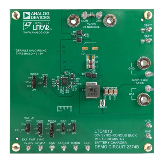
Page 2: Board Photo
DEMO MANUAL DC2374B BOARD PHOTO Rev. 0... -
Page 3: Typical Application
DEMO MANUAL DC2374B TYPICAL APPLICATION 24V 5A 6 Cell Lead Acid Charger with Absorption and Equalization Charging DCIN C2/10 10µF×2 68µF 4.7µF 4 STAGE CHARGING WITH 13.6V FLOAT, 14.2V ABSORPTION AND 15.0V EQUALIZATION INFET VIN_S 3.3 HR TIMEOUT DCIN 0.15µF 0.1µF... - Page 4 3. With power off, connect a 5.1A load (LOAD1) to BAT 1. Set the DC2374B to operate in a three stage lead acid and GND terminals in parallel with PS2 as shown in battery charging mode by positioning the jumpers as Figure 1.
- Page 5 DEMO MANUAL DC2374B 24V SUPPLY QUICK START PROCEDURE 6. Set PS1 to 17V and then turn on. 12. Make sure PS1 is set above UVLO rising threshold and set PS2 to about 12V. 7. Slowly increase PS1 until the STAT0 LED illuminates.
- Page 6 DEMO MANUAL DC2374B 24V SUPPLY QUICK START PROCEDURE Figure 1. Proper Measurement Equipment Setup Figure 2. Measuring Input or Output Ripple Rev. 0...
- Page 7 VMP for the measured V 1. Set the DC2374B to operate in MPPT mode with a three NOTE: If the charge current is reduced below C/10, stage lead acid battery charging mode by positioning...
- Page 8 DEMO MANUAL DC2374B MPPT QUICK START PROCEDURE 10. Slowly increase PS2 until the battery current starts 11. When the timer has elapsed, the LTC4013 will switch to decrease below 1A. The battery voltage is now to float mode and the charge current will drop to near approaching the absorption voltage.
- Page 9 DEMO MANUAL DC2374B MPPT QUICK START PROCEDURE Figure 4. Solar Simulator Using a Power Supply with Series Resistor Rev. 0...
-
Page 10: Application Information
It is recommended to pre-charge the BAT terminals of the 100mV, plus the ENAB pin must also be above its rising DC2374B prior to connecting a low ESR battery. This can threshold to startup. For single input FET applications V be done by connecting the battery thru a current limiting will increase to DCIN –... -
Page 11: Parts List
DEMO MANUAL DC2374B PARTS LIST ITEM REFERENCE PART DESCRIPTION MANUFACTURER/PART NUMBER Required Circuit Components CAP , CHIP , X5R, 4.7µF, ±10%, 50V, 0805 TDK, C2012X5R1H475K C2, C13, C21 CAP , CHIP , X5R, 68nF, ±10%, 50V, 0402 TDK, CGA2B3X5R1H683M050BB C3, C4 CAP , CHIP , X5R, 10µF, ±20%, 50V, 1210... - Page 12 DEMO MANUAL DC2374B PARTS LIST ITEM REFERENCE PART DESCRIPTION MANUFACTURER/PART NUMBER Additional Demo Board Circuit Components C5 (OPT) CAP , 68µF, 50V, Alum. Electro, 20%, 8mm x 10.2mm PANASONIC, EEHZA1H680P C6-C9, C22, C23 (OPT) CAP , CHIP , X5R, 10µF, ±20%, 50V, 1210...
-
Page 13: Schematic Diagram
DEMO MANUAL DC2374B SCHEMATIC DIAGRAM Rev. 0... - Page 14 Board until you have read and agreed to the Agreement. Your use of the Evaluation Board shall signify your acceptance of the Agreement. This Agreement is made by and between you (“Customer”) and Analog Devices, Inc. (“ADI”), with its principal place of business at One Technology Way, Norwood, MA 02062, USA. Subject to the terms and conditions of the Agreement, ADI hereby grants to Customer a free, limited, personal, temporary, non-exclusive, non-sublicensable, non-transferable license to use the Evaluation Board FOR EVALUATION PURPOSES ONLY.
Need help?
Do you have a question about the DC2374B and is the answer not in the manual?
Questions and answers