Table of Contents
Advertisement
Quick Links
Description
Demonstration circuit 2583 is an IEEE 802.3bt (Draft 2.3)
compliant Power over Ethernet (PoE) powered device
(PD). It features the
LT
4294
®
the LT4321 PoE ideal diode bridge controller.
The LT4294 provides IEEE 802.3af (PoE, Type 1),
IEEE 802.3at (PoE + , Type 2) and IEEE 802.3bt (PoE ++ ,
Type 3 and 4) compliant interfacing. It utilizes an external,
low R
(57mΩ typical) N-channel FET for the hot
DS(ON)
swap function to improve efficiency. Additional features
include power good (PWRGD) and T2P output indica-
tors for interfacing with downstream electronics. The
PWRGD output indicates the PD controller is ready to
provide power to the downstream load. This signal can be
used to enable an isolated power supply. The T2P output
indicates the available power from the power sourcing
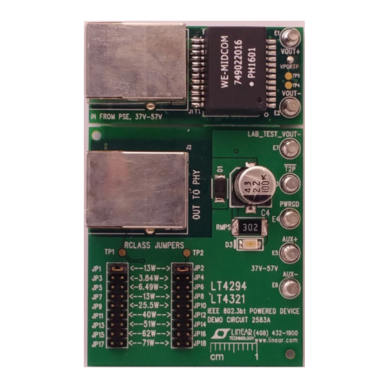
BoarD photo
PD interface controller and
Top Side
DEMO MANUAL DC2583A
IEEE 802.3bt Powered Device
equipment (PSE) to the downstream load. This signal can
be used to limit the load and prevent overloading the PSE.
The LT4321 controls eight low R
N-channel FETs to further improve end-to-end power
delivery efficiency and ease thermal design. This solu-
tion replaces the eight diodes typically found in a passive
PoE rectifier bridge.
The DC2583A accepts up to 71W of delivered power from
a PSE via the RJ45 connector (J1) or a local 48V DC
power supply using the auxiliary supply input. When both
supplies are connected, the auxiliary supply input has
priority over the PoE input.
Design files for this circuit board are available at
http://www.linear.com/demo/DC2583A
L, LT, LTC, LTM, Linear Technology, LTPoE ++ and the Linear logo are registered trademarks of
Analog Devices, Inc. All other trademarks are the property of their respective owners.
LT4294, LT4321
(57mΩ typical)
DS(ON)
Bottom Side
dc2583af
1
Advertisement
Table of Contents

Related Manuals for Analog Devices INEAR TECHNOLOGY DC2583A


Summary of Contents for Analog Devices INEAR TECHNOLOGY DC2583A
- Page 1 L, LT, LTC, LTM, Linear Technology, LTPoE ++ and the Linear logo are registered trademarks of Analog Devices, Inc. All other trademarks are the property of their respective owners. BoarD photo Top Side...
-
Page 2: Performance Summary
DEMO MANUAL DC2583A performance summary Specifications are at T = 25°C PARAMETER CONDITIONS UNITS Port Voltage (V At RJ45 PORT Auxiliary Voltage From AUX+ to AUX– Terminals Efficiency = 48V, I = 1.2A 99.2 PORT T2P Switching Frequency typical performance characteristics Top Side Bottom Side Figure 1. -
Page 3: Quick Start Procedure
DEMO MANUAL DC2583A Quick start proceDure Power Over Ethernet (PoE) Input 4. Connect the output of the IEEE 802.3bt compliant PSE (see note) to the RJ45 connector (J1) of the DC2583A 1. Disconnect auxiliary supply if it is connected to AUX+ using a CAT5e or CAT6 Ethernet cable. - Page 4 DEMO MANUAL DC2583A Quick start proceDure DC/DC CONVERTER CAT5e RJ45 RJ45 CAT6 CABLE IEEE 802.3bt LOAD – ENABLE PSE TYPE OPTO (TO µP) DC2583 F03 Figure 3. Setup Diagram for DC2583A with a DC/DC Converter, a Microprocessor and an IEEE 802.3bt PSE CAT5e RJ45 RJ45...
- Page 5 DEMO MANUAL DC2583A Quick start proceDure Auxiliary Supply Input output voltage to 48V. 1. Place and connect test equipment as shown in Figure 5. 4. Once the LED (D3) on the DC2583A is lit, check the output voltage using a voltmeter. Output voltage should 2.
-
Page 6: Parts List
DEMO MANUAL DC2583A parts list ITEM REFERENCE PART DESCRIPTION MANUFACTURER/PART NUMBER Required Circuit Components C1, C5 CAP ., 0.047µF, X7S, 100V, 10%, 0603 TDK, C1608X7S2A473K080AB CAP ., OPTION, 0402 CAP ., 0.047µF, X7R, 100V, 10%, 0805 AVX, 08051C473KAT2A CAP ., 1000pF, X7R, 2000V, 10%, 1808 TDK, C4520X7R3D102K130KA CT1, CT2, CT3, CT4 CAP , CER, X7R 0.01µF 200V 10%, 0805... - Page 7 DEMO MANUAL DC2583A parts list ITEM REFERENCE PART DESCRIPTION MANUFACTURER/PART NUMBER Hardware: For Demo Board Only CAP ., ALUM. ELECT., 22µF, 100V, 20% SUN ELECTRONIC, 100CE22BS CAP ., 1000pF, X7R, 2000V, 10%, 1808 TDK, C4520X7R3D102K130KA LED, GREEN, 560nm, 3x2mm, 1206 ROHM, SML-010FTT86L DIODE, 12V, 200mW, SOD-323 DIODES INC, MMSZ5242BS-7-F...
-
Page 8: Schematic Diagram
DEMO MANUAL DC2583A schematic Diagram RCLASS++ VPORTN RCLASS dc2583af... - Page 9 DEMO MANUAL DC2583A schematic Diagram dc2583af Information furnished by Linear Technology Corporation is believed to be accurate and reliable. However, no responsibility is assumed for its use. Linear Technology Corporation makes no representa- tion that the interconnection of its circuits as described herein will not infringe on existing patent rights.
- Page 10 DEMO MANUAL DC2583A DEMONSTRATION BOARD IMPORTANT NOTICE Linear Technology Corporation (LTC) provides the enclosed product(s) under the following AS IS conditions: This demonstration board (DEMO BOARD) kit being sold or provided by Linear Technology is intended for use for ENGINEERING DEVELOPMENT OR EVALUATION PURPOSES ONLY and is not provided by LTC for commercial use.
- Page 11 Mouser Electronics Authorized Distributor Click to View Pricing, Inventory, Delivery & Lifecycle Information: Analog Devices Inc. DC2583A...
Need help?
Do you have a question about the INEAR TECHNOLOGY DC2583A and is the answer not in the manual?
Questions and answers