Table of Contents
Advertisement
Quick Links
High Voltage Two 2-Channel PMBus Power System
DESCRIPTION
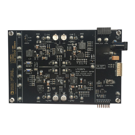
The DC2875A is a demonstration system for the
Power System Manager that interfaces to various regula-
tors. The board contains all the circuitry needed to demon-
strate a power system that utilizes two 2-channel LTC2971
devices that manage four power supplies. The four power
supplies include various switching regulators for the pur-
pose of demonstrating a variety of methods to sense volt-
age and current. The demo board provides a sophisticated
4-channel digitally programmable power supply system.
The LTC2971 is a 2-channel I
System Manager that features accurate input current
and energy measurement and is capable of managing
±60V supplies. The device monitors input current and
input voltage, and calculates input power and energy.
The DC2875A demonstrates the ability of the LTC2971
to sequence, trim, margin, supervise, monitor, and log
faults for four power supplies. The LTC2971 monitors
each channel's output voltage and output current and also
monitors each channel's external temperature sensor and
its own internal die temperature.
The DC2875A board contains four independent power
supply rails. All four rails are based on DC/DC switching
regulators. The +36V and +32V channels are managed by
an LTC2971 and the ±24V channels are managed by an
LTC2971-1. The board is pre-configured with these volt-
ages and may be re-configured with feedback resistors.
The LTpowerPlay
graphical user interface (GUI) sup-
®
ports this demonstration system and enables complete
control of all the features of the LTC2971. Together, the
LTpowerPlay software and DC2875A hardware system
create a powerful development environment for design-
ing and testing configuration settings of the LTC2971.
LTpowerPlay stores these settings in the LTC2971 internal
EEPROM or in a project file. The software displays all of
the configuration settings and real time measurements
from the Power System Management IC. Telemetry allows
easy access and decoding of the fault log created by the
LTC2971. The board comes preprogrammed with the
Managers with Four Power Supply Rails
LTC
2971
®
2
C/SMBus/PMBus Power
DEMO MANUAL DC2875A
EEPROM values appropriate for the four power supply
rails on the DC2875A. Just plug and play!
Order preprogrammed devices from Analog Devices
Express (ADX) using LTpowerPlay:
com/en/design-center/device-programming.html
The following items are required:
• +12VDC Power Supply
2
• USB-to-I
C/SMBus/PMBus Controller (DC1613)
• LTpowerPlay Software
DC2875A FEATURES
• Sequence, Trim, Margin, and Supervise Four
Power Supplies
• Manage Faults, Monitor Telemetry, Create Fault Logs
• PMBus Compliant Command Set
• Supported by LTpowerPlay GUI
• Margin or Trim Supplies to 0.25% Accuracy
• Four I
and Two I
OUT
IN
• Input Power Measurement and Energy Accumulation
• Fast OV/UV Supervisors per Channel
• Multi-Channel Fault Management
• Automatic Fault Logging to Internal EEPROM
• Operates Autonomously without Additional Software
• Monitors: Voltage, Current, Power, Temperature
• 2-Channel Time-Based Output Sequencer
2
• I
C/SMBus Serial Interface
• Powered from 8V to 18V
Design files for this circuit board are
All registered trademarks and trademarks are the property of their respective owners. Protected
by U.S. patents, including 7382303, 7420359, and 7940091.
LTC2971
https://www.analog.
Monitors
available.
Rev. 0
1
Advertisement
Table of Contents

Subscribe to Our Youtube Channel
Related Manuals for Analog Devices DC2875A


Summary of Contents for Analog Devices DC2875A
- Page 1 LTC2971 High Voltage Two 2-Channel PMBus Power System Managers with Four Power Supply Rails DESCRIPTION The DC2875A is a demonstration system for the 2971 EEPROM values appropriate for the four power supply ® Power System Manager that interfaces to various regula- rails on the DC2875A.
-
Page 2: Performance Summary
DEMO MANUAL DC2875A PERFORMANCE SUMMARY Specifications are at T = 25°C PARAMETER CONDITIONS VALUE Supply Input Operating Range 4.5V to 60V* Supply Input Operating Range 3.13V to 3.47V DD33 ADC V Total Unadjusted Error (TUE) 10V ≤ V ≤ 60V ±0.25%... -
Page 3: Glossary Of Terms
4. USB to I C/SMBus/PMBus Controller observe system response and faults. +12V POWER SUPPLY CH0: +36V USB TO TWO LTC2971s CH1: +32V C/SMBus/PMBus 4-CH DEMO BOARD CH2: +24V DONGLE (DC1613) (DC2875A) CH3: –24V DC2875A F01 Figure 1. DC2875A Demo Setup Rev. 0... - Page 4 You can use LTpowerPlay to ing the DC2875A demo system or a customer board. The evaluate Analog Devices ICs by connecting to a demo software also provides an automatic update feature to board system.
-
Page 5: Quick Start Procedure
GUI by using either function key F12 to write an individual register or use the Write All icon to write all registers, Figure 3. Connecting DC2875A and the DC1613 USB to you may need these settings for future use. Save I2C/SMBus/PMBus Controller the demo board configuration to a (*.proj) file by... - Page 6 DEMO MANUAL DC2875A QUICK START PROCEDURE the board defaults into the RAM and NVM of 2. Click on the “Go Online” icon: both LTC2971 devices. 7. The LTC2971 is configured to use the CONTROL switch to sequence on/off the four channels. Slide the then click on the “PC →...
- Page 7 COMMON BOARD OPERATIONS OVERVIEW A simplified block diagram of the DC2875A is shown in Figure 5. Each LTC2971 measures input current with a 50mΩ sense resistor for their managed channels. Each device also controls, monitors, and supervises its two outputs. Figure 5. Simplified Block Diagram of the DC2875A...
-
Page 8: Powering The Board
GND quickly when the channel is disabled. This is useful when sequencing off then on quickly. CONTROLLING/SEQUENCING CHANNELS By default, all four channels on the DC2875A board are controlled by a single CONTROL switch S1. DC2875A F07 To demonstrate time-based sequencing, let’s use the RUN Figure 7. - Page 9 To clear a fault, the user can click the CF icon in the GUI or simply push the RESET pushbutton (SW1) on the DC2875A demo board. In both cases, the red (+) on the CF icon and alert LED on the board are both cleared. Notice that all rails are automatically re-enabled after a program- mable retry period.
- Page 10 It is a power- leading up to the time of fault. Telemetry data is continu- ful diagnostic feature of the LTC2971 on the DC2875A ously updated in a circular RAM buffer in the LTC2971. demo board.
- Page 11 DEMO MANUAL DC2875A ADVANCED DEMO BOARD OPERATIONS CREATE A FAULT LOG To create a fault log, check that the fault_log_enable bit is set in the MFR_CONFIG_ALL register. Then, create a fault, as described in the section Creating a Fault. If multiple...
- Page 12 DEMO MANUAL DC2875A ADVANCED DEMO BOARD OPERATIONS FAULT SHARING SETUP IN THE GUI FAULT CONFIGURATION EXAMPLE Fault sharing provides a means of propagating a fault Let’s explore two different examples. Suppose we do detected by a power manager to other power managers not want channel CH2 (+24V rail) to propagate its fault via FAULT pins.
-
Page 13: Energy Metering
The DC2875A demo board uses two LTC2971 power managers that measure the voltage and current for each pair of outputs. Each LTC2971 is able to monitor and measure two outputs and its input power supply. - Page 14 IR drop. The networks. Voltage sensing employed on the DC2875A is channels are preprogrammed with a value of 50 in the easy. The appropriate VOUT_SNS and GNDSNS pins are IOUT_CAL_GAIN registers.
-
Page 15: Servo Circuits
DEMO MANUAL DC2875A ADVANCED DEMO BOARD OPERATIONS been exceeded, the ALERT pin will be asserted low and The equation below is used to derive the register values: the LED will illuminate. The channel will not be shut down. – V... - Page 16 2. Ensure different slave address settings for each of the into the GUI. boards. The address of each DC2875A board is set by ATTENTION: Once the GUI has launched, click the the DIP switch JP2 on the backside of the board. The “RAM →...
- Page 17 DEMO MANUAL DC2875A SETUP PROCEDURE FOR MULTI-BOARD ARRAYS APPLY +12V POWER TO ONLY ONE DC2875A BOARD SET TO DIFFERENT ADDRESSES USING DIPSWITCH JP2 ON BACKSIDE DC2875A F12 Figure 14. Array of Multiple Board Sets Rev. 0...
- Page 18 ENSURING SLAVE ADDRESSES DO NOT CONFLICT There is a small DIP switch on the backside of the DC2875A. It is used to set the slave address of an I/O expander which allows the addition of multiple boards to a setup. The I/O expander has a base address of 0x20. The DIP switch settings set the offset.
- Page 19 DEMO MANUAL DC2875A DC2875A DETAILS TOP Table 1. DC2875A – Default Switch Configuration REFERENCE DESIGNATOR SIGNAL NAME USAGE DEFAULT VDDIO Sets I/O Voltage for I C and Other Digital Signals 3.3V JP2 (Bottom) A0, A1, A2 DIP Switch Used to Set the Address Offset...
- Page 20 DEMO MANUAL DC2875A DC2875A DETAILS BOTTOM Rev. 0...
- Page 21 DEMO MANUAL DC2875A DC2875A SCHEMATIC DIAGRAM Rev. 0...
- Page 22 DEMO MANUAL DC2875A DC2875A SCHEMATIC DIAGRAM Rev. 0...
- Page 23 DEMO MANUAL DC2875A DC2875A SCHEMATIC DIAGRAM Rev. 0...
- Page 24 DEMO MANUAL DC2875A DC2875A SCHEMATIC DIAGRAM Rev. 0...
- Page 25 DEMO MANUAL DC2875A DC2875A SCHEMATIC DIAGRAM Rev. 0...
- Page 26 DEMO MANUAL DC2875A DC2875A SCHEMATIC DIAGRAM Rev. 0...
- Page 27 DEMO MANUAL DC2875A DC2875A SCHEMATIC DIAGRAM Rev. 0...
- Page 28 DEMO MANUAL DC2875A DC2875A SCHEMATIC DIAGRAM Rev. 0...
- Page 29 Devices for its use, nor for any infringements of patents or other rights of third parties that may result from its use. Specifications subject to change without notice. No license is granted by implication or otherwise under any patent or patent rights of Analog Devices.
- Page 30 Board until you have read and agreed to the Agreement. Your use of the Evaluation Board shall signify your acceptance of the Agreement. This Agreement is made by and between you (“Customer”) and Analog Devices, Inc. (“ADI”), with its principal place of business at One Technology Way, Norwood, MA 02062, USA. Subject to the terms and conditions of the Agreement, ADI hereby grants to Customer a free, limited, personal, temporary, non-exclusive, non-sublicensable, non-transferable license to use the Evaluation Board FOR EVALUATION PURPOSES ONLY.
Need help?
Do you have a question about the DC2875A and is the answer not in the manual?
Questions and answers