Sony PWS-110RX1A Service Manual
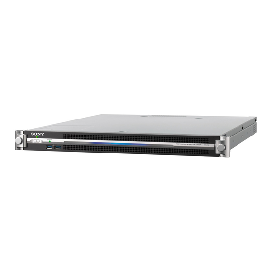
Network rx station and optional power supply
Hide thumbs
Also See for PWS-110RX1A:
- Operation manual (78 pages) ,
- Help manual (40 pages) ,
- Quick installation manual (13 pages)

Related Manuals for Sony PWS-110RX1A


Summary of Contents for Sony PWS-110RX1A
- Page 1 NETWORK RX STATION PWS-110RX1A OPTIONAL POWER SUPPLY PWSK-101 SERVICE MANUAL 1st Edition...
- Page 2 For safety, do not connect the connector for peripheral device wiring that might have excessive voltage to the following port(s). : LAN 1 connector : LAN 2 connector : REMOTE 1/2 connector : REMOTE 3/4 connector : REMOTE 5 connector Follow the instructions for the above port(s). PWS-110RX1A...
- Page 3 Batterien nur durch den vom Hersteller empfohlenen Kasser batteriet i henhold til gjeldende avfallsregler. oder einen gleichwertigen Typ ersetzen. Wenn Sie die Batterie entsorgen, müssen Sie die Gesetze der jeweiligen Region und des jeweiligen Landes befolgen. PWS-110RX1A...
- Page 4 Operation Manual. 6. When performing the installation, keep the following space away from walls in order to obtain proper exhaust and radiation of heat. Right, Left: 4 cm (1.6 inches) or more Rear: 10 cm (3.9 inches) or more PWS-110RX1A...
-
Page 5: Table Of Contents
Displaying Maintenance Web Screen................. . 3-1 PWS-110RX1A... - Page 6 Supplied Accessories......................6-6 PWS-110RX1A...
- Page 7 Overall..........................7-1 Revision History PWS-110RX1A...
-
Page 9: Manual Structure
Extended equipment Equipment including power supply unit (option PWSK-101) can be additionally installed in this unit. Information on optional equipment that is not equipped as standard may be provided in “Service Overview” - “Replacement of Main Parts” in this manual. PWS-110RX1A... -
Page 11: Service Overview
Board Name Circuit Function LED-527 Front Panel LED MB-1204 PCIe Switch, Storage Block SW-1627 Power SW Panel RC-110 PCI Express Riser Card DIO-98 USB3.0 Output CN-3698 Rear Connector HPR-48 XAVC 4K/HD Codec Card IF-1330 CPU Board Interface CN-3934 Internal Connector PWS-110RX1A... -
Page 12: Onboard Switch Settings, Led Functions, And Sensor Functions
Factory use S4002 MAIN BOARD ID Factory use ON: Activated in the PEC4 Back Up Mode. OFF: Activated in the PEC4 Normal Mode. ON: Activated in the CPU Back Up Mode. OFF: Activated in the CPU Normal Mode. Factory use PWS-110RX1A... - Page 13 Ref. No. Name Description Factory Setting S800 POWER Factory use MB-1204 Board S902 S800 S2200 S2201 MB-1204 board (side A) Ref. No. Name Description Factory Setting S800 Factory use OFF (ALL) S902 RESET Factory use S2200 RESET Factory use Continued PWS-110RX1A...
-
Page 14: Functions Of Onboard Leds
Lights when the CFG4 configuration has been suc- cessfully completed. D3701 Factory use Blinks D6102 LOCK Green Factory use D6101 D6100 D2500 PEC4 Green Factory use D2501 D2502 D2503 Lights when the CFG4 configuration has been suc- cessfully completed. PWS-110RX1A... - Page 15 3.3 VSB power supply Yellow green Lights when the 3.3 VSB power is on. indicator MB-1204 Board D808 D807 D806 D805 D804 D803 D802 D903 D801 D1803 D1802 D1801 D1800 D2300 D2200 D2400 D2202 D2201 D2203 MB-1204 board (side A) PWS-110RX1A...
- Page 16 Indicates an abnormality in fan assembly FAN1 Normal: Off Abnormal: Red D102 Indicates an abnormality in fan assembly FAN2 Normal: Off Abnormal: Red Continued For location of Fan 1 to 5, Power unit A and B, refer to “5-3. Location of Main Parts”. PWS-110RX1A...
- Page 17 Blinking green (1 Hz): Startup or shutdown in progress Blinking orange (1 Hz): A warning occurred. Blinking red (4 Hz): An error occurred. For location of Fan 1 to 5, Power unit A and B, refer to “5-3. Location of Main Parts”. PWS-110RX1A...
-
Page 18: Functions Of Onboard Sensors
HPR-48 board (side A) Board Name Ref. No. Function HPR-48 IC2802 Temperature sensor IC3901 Temperature sensor MB-1204 Board IC804 IC2402 MB-1204 board (side B) MB-1204 board (side A) Board Name Ref. No. Function MB-1204 IC804 Temperature sensor IC2402 Temperature sensor PWS-110RX1A... -
Page 19: Led Indicator Of Power Unit
LED Indicator of Power Unit Power unit is equipped with one LED that indicates the state of power unit. Lights in green: All outputs (+12V and +5Vsub) are normal. Off: At least one of the outputs is abnormal. LED indicator PWS-110RX1A... -
Page 20: Software Update
Required file • Data file for update (Installation package) Note For obtaining the latest data file for update (Installation package), contact your local Sony Sales Office/Service Center. Preparation Connect the mouse and the keyboard to the USB connectors. Connect the monitor to the HDMI connector. -
Page 21: Installing Application Software
Installing Application Software Connect the USB flash memory that contains the data file for update (Installation package) to the USB connector on the unit. Open the Install package folder in the USB flash memory. Execute a setup.exe. Click [Install]. 1-11 PWS-110RX1A... - Page 22 User Account Control screen is displayed. Click [Yes] to start the installation. Sony SNMP PWS-100, Sony HKP Service PWS-100, Sony Web_Application_PWS-100 are installed and the built- in storage (RAID_PKG) is updated. A command prompt opens and closes during the installation. Wait until the installation finishes.
-
Page 23: Software Version Check After Update
Wait for at least 10 seconds, connect the power cord, and then turn on the unit. On the Control Panel window, select “Programs and Features” from “Programs”. On the displayed window, check the versions of Sony HKP Service, Sony SNMP, and Sony Web_Application_ PWS-100. - Page 24 On the displayed Maintenance Web screen, open Diagnosis screen and check the version of the built-in storage (RAID_PKG). Version Check of each module Check that the version of each module is correct in the Maintenance Web screen. Refer to “3-1-1. Displaying Maintenance Web Screen” about the Maintenance Web screen. 1-14 PWS-110RX1A...
-
Page 25: Software Update (For This System)
Before starting reinstallation or version update of software, uninstall installed software programs. Procedure On the [Control Panel], select “Programs and Features” from [Programs]. On the Programs and Features window, select “Sony MSQ-S321 PWS-100 PWS-300 for Win10” and then click [Uninstall]. User Account Control screen is displayed. - Page 26 Installing Application Software Procedure Connect the USB flash memory that contains the data file for update (.msi file) to the USB connector on the unit. Open the folder. Execute a .msi file. InstallShield wizard is started. Click [Next]. Click [Install]. 1-16 PWS-110RX1A...
- Page 27 Turn off the unit, and remove the power cord Wait for at least 10 seconds, connect the power cord, and then turn on the unit. On the Control Panel window, select “Programs and Features” from “Programs” in “Control Panel”. 1-17 PWS-110RX1A...
-
Page 28: Updating The Application For This System
Required files • Data file for update (Installation package) Note For obtaining the latest data file for update (Installation package), contact your local Sony Sales Office/Service Center. Preparation Connect the mouse and the keyboard to the USB connectors. Connect the monitor to the HDMI connector. - Page 29 Check that “StreamingReceiverAppInstallHelper.exe” is displayed for the program name. Click [Yes] to start the installation. Note A command prompt opens and closes during the installation. Wait until the command prompt closes. Initialization Refer to the procedure of Software Update Guide supplied with update data file. 1-19 PWS-110RX1A...
- Page 30 Software Version Check after Update Procedure Select [Programs and Features] from [Programs] in [Control Panel]. On the displayed window, check the version of RX1 Connection Control Manager, and RX1 Streaming Receiver. 1-20 PWS-110RX1A...
-
Page 31: Recovery Methods
Set Bit1 of the DIP switch (S2201) on the MB-1204 board to ON. (Refer to “MB-1204 Board” “1-2-1. Onboard Switch Settings”.) Install the top panel assembly. Turn on the unit to start Windows. Type “Settings” in the search box at the lower left of the window, and then click the Settings icon. 1-21 PWS-110RX1A... - Page 32 On the [Windows Settings] window, click [Update & security]. Click [Recovery]. Click [Restart now] in [Advanced startup]. 1-22 PWS-110RX1A...
- Page 33 On the [Choose an option] window, click [Troubleshoot]. 10. On the [Troubleshoot] window, click [Advanced options]. 11. On the [Advanced options] window, click [System Image Recovery]. Windows PE starts running. 1-23 PWS-110RX1A...
-
Page 34: Recovery By Using The Windows Pe
18. Turn on the unit and check that the Windows starts. 19. Upgrade the software. (Refer to “1-4. Software Update”.) 1-6-2. Recovery by Using the Windows PE If Windows does not start, carry out the following procedure for recovery. 1-24 PWS-110RX1A... - Page 35 Create Windows PE for Windows 10 64bit. Use version “for Windows10” of Windows PE. For details of creating bootable USB memory for Windows PE, contact your local Sony Sales Office/Service Center. Connect the USB memory to the unit. Press and hold the Delete key and turn on the unit.
-
Page 36: Recovery By Replacing Ssd Module
“1-6-2. Recovery by Using the Windows PE” is performed, the SSD module may be defective. In that case, replace the SSD module and make settings after replacement. (Refer to “5-16. SSD Module (M.2)” “5-2-2. SSD Module (M.2 Assembly)”.) 1-26 PWS-110RX1A... -
Page 37: Tools And Fixtures
Screw tightening Torque screwdriver (0.3 N • m) J-6325-400-A Screw tightening Torque screwdriver (0.6 N • m) J-6252-510-A Screw tightening Torque screwdriver (1.2 N • m) J-6252-520-A Screw tightening Box driver (size 6 mm) Commercially available Hexagon support tightening 1-27 PWS-110RX1A... -
Page 38: Circuit Protection Part List
After that, replace the fuses. Board Name Ref. No. Name Part No. HPR-48 F4200 FUSE 10 A/125 V 1-576-329-21 F4201 FUSE 10 A/125 V 1-576-329-21 Continued 1-28 PWS-110RX1A... - Page 39 FUSE 2.5 A/125 V 1-533-804-21 F1007 FUSE 8 A/125 V 1-576-328-21 MB-1204 F200 FUSE 15 A/65 V 1-576-566-21 F201 FUSE 15 A/65 V 1-576-566-21 F202 FUSE 2.5 A/125 V 1-533-804-21 RC-110 F100, F101 FUSE 5 A/125 V 1-533-627-21 1-29 PWS-110RX1A...
-
Page 40: Coaxial Cable
Do not attempt to disconnect by pulling the cable. Disconnecting Hold the connector between your finger tips and disconnect the fine-wire coaxial cable vertically. Connecting Hold the connector between your finger tips and connect the fine-wire coaxial cable vertically. 1-30 PWS-110RX1A... -
Page 41: Error Messages
• Only one power supply unit is operating and an abnormality was detected in it. • Two power supply units are operating and an abnormality was detected in one or two of them. For location of Fan 1 to 5, Power unit A and B, refer to “5-3. Location of Main Parts”. PWS-110RX1A... -
Page 42: Warnings
Further use of the SSD module decreases the parts as soon as possible. reliability of stored data and causes eventual failure of data writing. For location of Fan 1 to 5, Power unit A and B, refer to “5-3. Location of Main Parts”. PWS-110RX1A... -
Page 43: Snmp Trap Messages
We recommend that you replace parts as soon as possible. Further use of the SSD module decreases the reliability of stored data and causes eventual failure of data writing. • Power supply unit No.: A, B • Fan assembly No.: 1 to 5 PWS-110RX1A... -
Page 45: Maintenance Menu
For more information on Maintenance Web screen, refer to the operation manual of the PWS-100 Maintenance Web Application. For the models with OS pre-installed, the operation manual of the PWS-100 Maintenance Web Application is stored in the system drive of the unit. PWS-110RX1A... -
Page 47: Periodic Maintenance And Inspection
This section describes the recommended replacement parts and recommended replacement time. This table does not describe the guarantee period of part. The replacement period of each part is changed according to the environment and condition. Part name Sony parts No. Hour meter Check/replacement Reference... -
Page 49: Replacement Of Main Parts
Tightening torque M2: 0.30 ±0.02 N·m M2.6: 0.53 ±0.07 N·m M3: 0.80 ±0.12 N·m M4: 1.4 ±0.2 N·m When using the torque driver with the notation of cN· m, interpret it as follows. Example: 0.8 N·m = 80 cN·m PWS-110RX1A... -
Page 50: Actions To Be Taken Before/After Replacement
After Replacing the iAP Board Assembly When the iAP board assembly was replaced, the BIOS must be updated. Before upgrading the BIOS, replace the battery with a new one because the battery on the iAP board assembly from parts center may have drained. PWS-110RX1A... - Page 51 • Bootable USB memory (Refer to “5-2-7. Example of Creating Bootable USB Memory”.) Note For obtaining the BIOS update file required to create bootable USB memory, contact your local Sony Sales Office/ Service Center. • A USB mouse • A USB keyboard •...
-
Page 52: Example Of Creating Bootable Usb Memory
Click [Write] to write the DOS image to the USB flash memory. Click [Exit] to exit the application programs. Copy necessary files to the USB flash memory. Example) The following three files are necessary for BIOS Update. • Update.bat • AFUDOS.exe • AxxxPxxx.ROM PWS-110RX1A... -
Page 53: Location Of Main Parts
If you need to replace the fan mounted on the HPR-48 board, refer to “2-7. Replacement of Fan (Serial No.: 10001 to 11000, 70001 to 71000)” in the MSQ-S321 Service Manual. Fan Assembly (FAN1 to 5) “5-12. Fan Assembly” PWS-110RX1A... - Page 54 SSD Module (M.2) “5-16. SSD Module (M.2)” iAP-005 Board Assembly “5-17. iAP-005 Board Assembly” “5-18. CPU” Memory Module (260pin SO-DIMM) “5-19. Memory Module (260pin SO-DIMM)” IF-1330 Board “5-20. IF-1330 Board” CN-3934 Board “5-21. CN-3934 Board” MB-1204 Board “5-22. MB-1204 Board” PWS-110RX1A...
-
Page 55: Top Panel Assembly
Attach the top panel, and then tighten the three screws (B4 x 6). Tighten the six screws (PSW3 x 6). Note Press and hold down the top panel, and then tighten each screw. B4 x 6 Top panel PSW3 x 6 PSW3 x 6 PWS-110RX1A... -
Page 56: Front Panel Assembly
Disconnect the connector (CN100) on the LED-527 board from the connector (CN101) on the SW-1627 board and remove the front panel assembly. SW-1627 board CN101 LED-527 board CN100 Screw (anti-drop) Front panel assembly Screw (anti-drop) Install the removed parts by reversing the steps of removal. PWS-110RX1A... - Page 57 Release the hook, then slide the LED-527 board in the direction of the arrow A. Tilt the LED-527 board in the direction of the arrow B and remove the LED-527 board. Front panel assembly LED-527 board Hook Install the removed parts by reversing the steps of removal. PWS-110RX1A...
-
Page 58: Sw-1627 Board
Remove the two screws, then remove the bracket (SW) assembly in the direction of the arrow. Remove the SW-1627 board from the two pins of the bracket (SW) assembly. Wire saddle (C) SW-1627 board CN100 Bracket (SW) assembly Harness Pins PSW3 x 6 Install the removed parts by reversing the steps of removal. 5-10 PWS-110RX1A... -
Page 59: Dio-98 Board
• When installing the fine-wire coaxial cable, install it in the orientation shown in the figure. • When installing the DIO-98 board, insert the board to the two notches of the chassis. Install the removed parts by reversing the steps of removal. 5-11 PWS-110RX1A... -
Page 60: Power Unit
Pull up the lever in the direction of the arrow to unlock the power unit, and then pull the handle to draw out the power unit. Rear of this unit Power unit Power unit Handle Lever Installation Pull up the lever in the direction of the arrow, and then insert the power unit. 5-12 PWS-110RX1A... - Page 61 Align the hole to the boss, attach the rear panel (power), and then tighten the four screws. Note First tighten the screw (a), and then tighten the other three screws. (Refer to the figure below.) Rear of this unit Hole Boss B3 x 8 Rear panel (power) assembly B3 x 8 5-13 PWS-110RX1A...
-
Page 62: Hot-Swap Unit
Do not pull up the hot-swap unit without releasing the notch of the hot-swap unit from the positioning pin. Doing so may damage the positioning pin. PSW 3 x 6 Hot-swap unit Connector Notch Positioning pin Harness Install the removed parts by reversing the steps of removal. 5-14 PWS-110RX1A... -
Page 63: Hpr-48 Board
HPR-48 Board Note The following parts are not reusable. Prepare new parts in advance. • TD1 cushion U (65x85x22) (1) • TD1 cushion B (45x45x3) (1) Preparation Remove the top panel assembly. (Refer to “5-4. Top Panel Assembly”.) 5-15 PWS-110RX1A... - Page 64 On installation, when the PCI board support is not seen in the hole, slide it until it is seen in the hole. PCI board support Rear of this unit PCI board support check hole 5-16 PWS-110RX1A...
- Page 65 RC holder assembly PSW3 x 6 CN100 CN101 PSW3 x 6 MB-1204 board CN101 CN104 Rear of this unit PSW3 x 6 Note When installing the RC holder assembly, tighten the screws in the following sequence: (a), others. 5-17 PWS-110RX1A...
- Page 66 • Align the left edge of the TD1 cushion U to the line of the duct (fan) and fit the top and bottom of the cushion within the outline of the duct (fan). • Do not stick the TD1 cushion B over the screws. • When attaching the cushions, apply light pressure so that the board does not get deformed. Reassemble the unit. 5-18 PWS-110RX1A...
-
Page 67: Fan Assembly
Remove other fan assemblies (FAN2 to FAN5) in the same way as in step 2. Fan duct (110) Fan assembly (FAN1) Harness CN705 MB-1204 board Fan assemblies FAN5 FAN4 FAN3 FAN2 FAN1 CN703 CN701 CN702 CN705 CN704 Install the removed parts by reversing the steps of removal. 5-19 PWS-110RX1A... -
Page 68: Lithium Battery
Pull back the plate of the battery holder in the direction of the arrow A and remove the lithium battery in the direction of the arrow B. Lithium battery Plate of the battery holder iAP-005 board assembly Rear of this unit Install the removed parts by reversing the steps of removal. 5-20 PWS-110RX1A... -
Page 69: Cn-3698 Board
Procedure Remove the screw, and then remove the top panel bracket (L). Disconnect the harness from the connector (CN301) on the CN-3698 board. PSW3 x 6 Harness Top panel bracket (L) CN301 Rear of this unit CN-3698 board 5-21 PWS-110RX1A... - Page 70 Remove the screw (B2.6 x 5) and the screw (PSW3 x 6) to detach the CN-3698 board in the direction of the arrow. PSW3 x 6 CN-3698 board Rear of this unit B2.6 x 5 Install the removed parts by reversing the steps of removal. 5-22 PWS-110RX1A...
-
Page 71: Rc-110 Board
Remove the HPR-48 board. (Refer to “5-11. HPR-48 Board”.) Procedure Remove the screw to detach the RC-110 board in the direction of the arrow. RC holder assembly RC-110 board PSW3 x 6 Install the removed parts by reversing the steps of removal. 5-23 PWS-110RX1A... -
Page 72: Ssd Module (M.2)
Notch SSD module (M.2) PSW2.6 x 8 Connector iAP-005 board assembly Note When installing the SSD module, insert it securely into the connector of the iAP-005 board assembly. Install the removed parts by reversing the steps of removal. 5-24 PWS-110RX1A... -
Page 73: Iap-005 Board Assembly
When installing the rear panel assembly, align the three bosses (B) with the three holes (B). Open the three pieces of wire saddle (C). Disconnect the two harnesses from the connectors (CN201, CN807) on the MB-1204 board. Disconnect the harness from the connector (A) of the iAP-005 board assembly. 5-25 PWS-110RX1A... - Page 74 Harness Rear of this unit CN201 CN202 Connector (A) IF-1330 board Remove the four screws and detach the iAP-005 board assembly. Disconnect the two harnesses from the connector (B) and the connector (C) of the iAP-005 board assembly. 5-26 PWS-110RX1A...
- Page 75 PSW3 x 6 Harness iAP-005 board assembly Connector (B) iAP shield Note When installing the iAP-005 board assembly, tighten the screws in the following sequence: (a), (b), (c), (d). 10. Install the removed parts by reversing the steps of removal. 5-27 PWS-110RX1A...
-
Page 76: Cpu
Removal Remove the four screws, the four step washers and the four compression springs and detach the heat sink. Remove the radiation sheet 0.5 (30X30). B2.6 x 5 Step washers Compression springs Heat sink Radiation sheet 0.5 (30X30) 5-28 PWS-110RX1A... - Page 77 Align the two notches of the CPU with the two projections on the CPU socket, and then seat the CPU. Attach the insulating sheet, the bracket and the CPU retainer. Put four compression springs and four hexagon supports on the CPU retainer. 10. Press the CPU retainer and tighten the hexagon supports temporarily in diagonal sequence. 5-29 PWS-110RX1A...
- Page 78 When installing the iAP-005 CPU board, confirm that the connectors of the IF-1330 board are fully inserted. iAP-005 CPU board Connectors iAP-005 CPU board PSW2 x 5 Connectors of the IF-1330 board Connectors are fully inserted Contacts of the connector Connectors Connectors are incompletely inserted Contacts of the connector IF-1330 board 5-30 PWS-110RX1A...
- Page 79 16. Tighten the screws to the specified torque in the following sequence: (a), (b), (c), (d). B2.6 x 5 Step washers Compression springs Heat sink Radiation sheet 0.5 (30X30) 17. Assemble the unit by reversing the steps of "Preparation". 5-31 PWS-110RX1A...
-
Page 80: Memory Module (260Pin So-Dimm)
Memory module Note When installing the memory modules, insert them securely into the memory socket. Remove another memory module in the same way as in steps 1, 2. Install the removed parts by reversing the steps of removal. 5-32 PWS-110RX1A... -
Page 81: If-1330 Board
At the time of the installation, tighten the screws to the specified torque in the following sequence: (a), (b), (c), (d). Remove the five screws, and then remove iAP-005 CPU board from the connectors on the IF-1330 board. 5-33 PWS-110RX1A... - Page 82 IF-1330 board Connectors are incompletely inserted Contacts of the connector Connectors Note When installing the iAP-005 CPU board, confirm that the connectors of the IF-1330 board are fully inserted. Install the removed parts by reversing the steps of removal. 5-34 PWS-110RX1A...
-
Page 83: Cn-3934 Board
When disconnecting the connector with lead wire, pull out the connector part with your fingers. Remove the CN-3934 board in the direction of the arrow. Connectors with lead wires CN002 CN003 CN-3934 board Rear of this unit Install the removed parts by reversing the steps of removal. 5-35 PWS-110RX1A... -
Page 84: Mb-1204 Board
When pulling out the fine-wire coaxial cable, pull out the connector part with your fingers. Disconnect all harnesses connected to the MB-1204 board. CN701 CN702 CN703 CN704 CN705 Wire saddle (C) CN103 CN602 CN601 CN600 CN102 CN200 CN700 CN807 CN201 CN202 5-36 PWS-110RX1A... - Page 85 Slide the PCI board support in the direction of the arrow A, and then remove the PCI board support. Note The PCI board support is hard to slide because it is locked tightly enough not to disengage by vibration. PCI board support Rear of this unit PCI board support MB-1204 board 5-37 PWS-110RX1A...
- Page 86 CN102 PSW3 x 6 MB-1204 board Hooks Rear of this unit Note When installing the cable, install the fine-wire coaxial cable in the direction shown in the figure. Install the removed parts by reversing the steps of removal. 5-38 PWS-110RX1A...
-
Page 87: Spare Parts
Therefore, specified parts should be used in the case 指定の部品を使ってください。 of replacement. 2. Standardization of Parts 2. 部品の共通化 Some repair parts supplied by Sony differ from those ソニーから供給する補修用部品は,セットに使われ used for the unit. These are because of parts common- ているものと異なることがあります。 ality and improvement. -
Page 88: Exploded Views
A-2040-582-A s LED-527 MOUNT 7-682-947-01 s SCREW +PSW 3X6 A-2040-583-A s SW-1627 MOUNT *1 7-682-947-09 s SCREW +PSW 3X6 A-2040-588-B s DIO-98 MOUNT A-2128-417-A s PANEL (110) ASSY, FRONT [for SY] A-2219-018-A s PANEL (110RX1A) ASSY (CN),FRONT [for CN] PWS-110RX1A... -
Page 89: Main Block-1
SP Description A-2040-584-A s RC-110 MOUNT 4-587-955-01 s TD1 CUSHION B (45X45X3) A-2040-589-A s CN-3698 MOUNT 1-474-591-12 s OPTION 7-682-548-04 s SCREW +B 3X8 2-655-586-01 s SCREW +B M2.6 EG 7-682-947-01 s SCREW +PSW 3X6 4-587-954-01 s TD1 CUSHION U(65X85X22) PWS-110RX1A... -
Page 90: Main Block-2
1-970-066-11 s HARNESS, SUB (MB-IAP CPU PW) 1-970-067-11 s HARNESS, SUB (MB-IAP CTL) 1-970-161-11 s WIRE, CONNECTOR WITH LEAD 1-971-395-11 s HARNESS, SUB (MB-SHORT) 1-971-396-11 s HARNESS, SUB (MB-SW/DIO_B) 4-546-058-02 s SUPPORT, PCI BOARD 7-682-947-01 s SCREW +PSW 3X6 PWS-110RX1A... -
Page 91: Iap-005 Block
4-726-507-01 s SQUARE, HEAT SINK (100) 6-723-527-01 s IC CM8066201937801S-R2LP 1-897-138-11 s MOUNTED CPU BOARD, IAP-005 6-724-230-01 s IC HMA851S6CJR6N-VKN0 2-655-586-01 s SCREW +B M2.6 EG 3-669-607-22 s +PSW (SMALL ROUND) (2.6) 7-628-000-05 s +PSW 2X6 4-273-810-01 s SHAFT, COM SUPPORT PWS-110RX1A... -
Page 92: Supplied Accessories
6-3. Supplied Accessories Q'ty Part No. SP Description 1pcs 1-833-005-12 s AC POWER-SUPPLY CORD (Supplied for CN) PWS-110RX1A... - Page 93 DDR3 SDRAM IC2802 X6100:148.5MHz IC6101 X6101 TEMP SENSOR CLOCK 27MHz IC2803 IC2805, IC2806 IC6205 IC6001-6004 IC6005 DC FAN RS232C +12V TX/RX (50 SQUARE) BUFFER BUFFER EQ/DRV SYNC SEP CN2801 CN2802 CN2800 CN6205 CN6206 CN6001 CN6002 232C IMX6 EPR2 SDI REF PWS-110RX1A...
- Page 95 Revision History Date History Contents 2018. 7 1st Edition ― 9-932-633-01 PWS-110RX1A...
- Page 98 PWS-110RX1A (SY) Printed in Japan Sony Corporation PWS-110RX1A (CN) J, E 2018. 7 08 9-932-633-01 © 2018...
Need help?
Do you have a question about the PWS-110RX1A and is the answer not in the manual?
Questions and answers