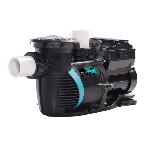
Pentair INTELLIFLOXF Installation And User Manual
Variable speed pump
Hide thumbs
Also See for INTELLIFLOXF:
- Installation and user manual (48 pages) ,
- Installation and user manual (36 pages)

Related Manuals for Pentair INTELLIFLOXF


Summary of Contents for Pentair INTELLIFLOXF
- Page 1 ® ® INTELLIFLO INTELLIPRO VARIABLE SPEED PUMP INSTALLATION AND USER’S GUIDE IMPORTANT SAFETY INSTRUCTIONS READ AND FOLLOW ALL INSTRUCTIONS SAVE THESE INSTRUCTIONS...
-
Page 2: Important Safety Instructions
This guide provides installation and operation instructions for this pump. • The pump is not submersible. Consult Pentair with any questions regarding this equipment. • The pump is capable of high flow rates; use caution when installing and Attention Installer: This guide contains important information about the programming to limit pumps performance potential with old or questionable installation, operation and safe use of this product. - Page 3 IMPORTANT SAFETY INSTRUCTIONS TO MINIMIZE THE RISK OF INJURY DUE TO HAZARDOUS PRESSURE: STAND CLEAR OF PUMP SUCTION ENTRAPMENT HAZARD: AND FILTER DURING START UP. Circulation systems operate under high pressure. When • A properly installed and secured ANSI/ASME A112.19.8 approved anti- any part of the circulating system (i.e.
-
Page 4: Table Of Contents
CUSTOMER SERVICE / TECHNICAL SUPPORT If you have questions about ordering Pentair replacement parts, and pool products, please contact: Customer Service and Technical Support, USA Sanford, North Carolina (8 A.M. to 4:30 P.M. ET) (8 A.M. to 4:30 P.M. — Eastern/Pacific Times) -
Page 5: Pump Overview
PUMP OVERVIEW External Control The IntelliFloXF Variable Speed Pump can be ® programmed to run at specific speeds and time IntelliTouch , EasyTouch , SunTouch Control Systems ® ® ® intervals for maximum operating efficiency and energy and IntelliComm Communication Centers can remotely ®... -
Page 6: Installation
INSTALLATION Only a qualified plumbing professional should install the IntelliFloXF and IntelliProXF Variable Speed Pumps. Refer to ® ® “Important Safety Instructions” on pages i - ii for additional installation and safety information. Location Note: Do not install this pump within an outer enclosure or 6 IN. -
Page 7: Electrical Installation
POWER LINE TERMINALS. Pentair offers 2-Pole 20 Amp GFCI breakers (P/N PA220GF) which offer 6 milliamp personnel Drive Wiring protection while meeting 2008 to current NEC Connection Standards for Pool Pumps. -
Page 8: Operating The Pump
OPERATING THE PUMP NOTE: Speed 1 is the default filtration speed. NOTE: When setting up the pump, the user must set the pump’s internal clock and establish an operation schedule by following the steps in this manual. Please refer to user’s guide sections: ‘Set Time’ (page 8) and ‘Set Speeds 1-8 in Schedule Mode’ (page 11) to schedule a time to run the pump. -
Page 9: Using The Control Panel
Using the Control Panel Key Lockout Icon Use the operator control panel to start and stop the pump, program, set, and change speeds (RPM), and access pump features and settings. 12:15p Controls and LEDs on Keypad: 750 RPM 750 RPM Button 1: Press to select Speed 1 (750 RPM). -
Page 10: Stopping And Starting The Pump
Stopping and Starting the Pump Pump Operating Modes The pump can be programmed in three different modes: Starting the Pump Manual, Schedule, and Egg Timer: Speeds 1-4 can be 1. Be sure the pump is powered on and the green programmed in all three modes. -
Page 11: Control Panel Menu Guide
Control Panel: Pump Menu Guide MENU Press MENU button to access menus SETTINGS Set Date and Time Date Months (1-12) Days (1-31) (pages 8-10) Years (2000-2050 Plus) Time Hours (24hr Mode: 0-23) (12hr Mode: 1-12 AM & PM) Minutes (0-60) Hour Format AM/PM - Default: AM/PM 24 Hour... -
Page 12: Pump Settings
1-16. The IntelliTouch system can communicate to only four (1-4) pumps. Set Minimum Speed (RPM) Note: IntelliFloXF pumps cannot be connected in series The minimum pump speed can be set from 450 RPM to with other pumps. -
Page 13: Set Screen Contrast
MENU Pump Menu: Settings SETTINGS Pump Address (1-16) Default: ADDRESS 1 Set Time (hr:mm) Default: 12:00 AM Pump Address Set Temperature Unit (cont.) AM/PM 5. Use the Up or Down arrows to scroll to “Pump Address” Set AM/PM The pump can be set to either Celsius (°C) or Fahrenheit 24 hr. -
Page 14: Setting Password
MENU MENU Pump Menu: Settings Pump Menu: Speeds 1-8 Manual SETTINGS Pump Address (1-16) Default: ADDRESS 1 SPEED 1-8 Speed 1 (1-4) Set Speed Schedule Set Speed Set Time (hr:mm) Default: 12:00 AM Set Start T Setting Password Pump Operating Modes Set Stop T AM/PM Set AM/PM... -
Page 15: Setting Speeds In Manual Mode
MENU Pump Menu: Speeds 1-8 Manual SPEED 1-8 Speed 1 (1-4) Set Speed - Default: MANUAL Schedule Set Speed Set Start Time Set Speeds in Manual Mode Set Speeds 1-8 in Schedule Mode Set Stop Time (Speeds 1-4 Only) Egg Timer In Schedule mode, Speeds 1-8 can be programmed Set Speed Time... -
Page 16: External Control
MENU MENU Pump Menu: External Pump Menu: Speeds 1-8 Manual Speed - Default: 750 RPM SPEED 1-8 Speed 1 (1-4) EXT CONTROL Program 1 Set Speed - Default: MANUAL Control Schedule Set Speed Speed - Default: 1500 RPM Program 2 Set Start Time External Control Set Speeds 1-8 in Schedule Mode... -
Page 17: Features
MENU 8. Press Save to save the speed. 9. Press the Down arrow again, and press Select for Pump Menu: Features Time Out Time Out Duration (1 min. to 10 hrs.) Default: 3 hours FEATURES “Time Duration”. 10. Press Select to change the time. The cursor will Set Speed (1100 -3450 RPM) Default: 3450 RPM Quick Clean Time Out... -
Page 18: Priming Features
MENU Pump Menu: Priming PRIMING Default: Enabled DISABLED/ENABLED (1 min. to 30 min. hrs.) Default: 11 minutes MAX PRIMING TIME Priming Features (1 - 100%) Default: 1 PRIMED SENSITIVITY Default: ENABLED DISABLED/ENABLED (1 second - 10 minutes) Default: 20 seconds PRIMING DELAY Allows pump to automatically detect if pump if is primed for startup. -
Page 19: Setting Priming Features
MENU Pump Menu: Priming PRIMING Default: Enabled DISABLED/ENABLED (1 min. to 30 min. hrs.) Default: 11 minutes MAX PRIMING TIME Setting Priming Features 16. Press Save to save the setting. 17. Press Back to exit. Note: Priming features are only accessible if priming (1 - 100%) Default: 1 PRIMED SENSITIVITY is “Enabled”. -
Page 20: Thermal Mode
MENU Pump Menu: Thermal Mode Disabled / Enabled - Default: Enabled THERMAL MODE DISABLED/ENABLED PRIMING Default: Enabled DISABLED/ENABLED SET SPEED Set Speed (750 RPM - 3450 RPM) Default 1000 RPM (1 min. to 30 min. hrs.) Default: 11 minutes MAX PRIMING TIME The sensor for Thermal Mode is in the drive, on top of the To Set Thermal Mode Speed and Pump Temperature: motor. -
Page 21: Connecting To An Automation System
For more information, refer to the IntelliTouch (P/N 520100) or EasyTouch Automation address is “1” (only address for EasyTouch system). System User’s Guide (P/N 520584). Installation and User’s Guides are available at: www.pentair.com. ® ® INTELLIFLO and INTELLIPRO... - Page 22 To connect the pump communication cable to EasyTouch or IntelliTouch Control System load center: ® ® IntelliTouch COM port (J7/8): Connect the 1. Switch the main power off to the load center. GREEN (#2) and YELLOW (#3) wires to the COM 2.
-
Page 23: Connecting To Suntouch Systems
Connecting the Pump to a SunTouch Control System ® The pump can be controlled by a SunTouch system via Switch OFF main system power to the SunTouch the RS-485 communication cable. system power center before making any connections. To connect the pump RS-485 communication cable to 4. -
Page 24: Maintenance
MAINTENANCE DO NOT open the strainer pot if pump fails to prime or if pump has been operating without water in the strainer pot. Pumps operated in these circumstances may experience a build up of vapor pressure and may contain scalding hot water. Opening the pump may cause serious personal injury. -
Page 25: Motor And Drive Care
Always disconnect power to the pump at the circuit breaker and disconnect the communication cable before servicing the pump. Failure to do so could result in death or serious injury to service people, users or others due to electric shock. Read all servicing instructions before working on the pump. -
Page 26: Shaft Seal Replacement
Pump Reassembly Shaft Seal Replacement Using a 9/16” wrench, secure the seal plate to The Shaft Seal consists of two halves, a rotating spring seal the motor with the four motor nuts. Tighten to and a fixed ceramic seal. The shaft seal may occasionally 75-80 in-lbs. -
Page 27: Drive Assembly Removal And Installation
Drive Assembly Removal and Installation FIRE and BURN HAZARD - The pump motor may run at a high temperatures. To reduce the risk of fire, do not allow leaves, debris, or foreign matter to collect around the pump motor. To avoid burns when handling the motor, shut off the motor and allow it to cool for 20 minutes before servicing. -
Page 28: Troubleshooting
DC buss. The drive will restart 20 seconds after the over voltage condition clears. Internal Error Indicates that the self-monitoring motor control software has encountered an error. Clear the alarm and restart the pump. If this alarm persists, contact Pentair Technical Service at 1-800-831-7133. ® ® INTELLIFLO and INTELLIPRO Variable Speed Pump Installation and User’... -
Page 29: Troubleshooting Chart
Troubleshooting Chart Problem Possible Cause Corrective Action Pump failure. Pump will not prime - Air leak in suction. Check suction piping and valve glands on any suction gate PRIME ERROR may be displayed. valves. Secure lid on pump strainer pot and be sure lid (For alert display gasket is in place. - Page 30 Troubleshooting Chart, (continued) Problem Possible Cause Corrective Action Electrical problem. Could appear as a “Low Voltage” alarm. Check voltage at motor terminals and at panel while pump is running. If low, see wiring instructions or consult power (For alert display company.
-
Page 31: Replacement Parts
REPLACEMENT PARTS Item IntelliFloXF IntelliProXF Item IntelliFloXF IntelliProXF Description Description Part # Part # Part # Part # Drive Kit 356879Z 356893Z Diffuser 400010 Power End Kit 400655Z 401655Z Diffuser Screws 353323 Drive Hardware Kit 355685 Diffuser O-ring 350336 Wet End Assembly... -
Page 32: Pump Performance Curves
Pump Performance Curves Max. Speed @3450 rpm Speed 4 @3110 rpm Speed 3 @2350 rpm Speed 2 @1560 rpm Speed 1 @750 rpm 100 110 120 130 140 150 160 170 180 190 200 210 220 230 Volumetric Flow Rate in GPM Electrical Specifications Circuit Protection: Two-pole 20 AMP device at the Electrical Panel. -
Page 33: Pump Menu Quick Reference Guide
Pump Menu Quick Reference Guide MENU Press MENU button to access menus SETTINGS Set Date and Time Date Months (1-12) Days (1-31) (pages 8-10) Years (2000-2050 Plus) Time Hours (24hr Mode: 0-23) (12hr Mode: 1-12 AM & PM) Minutes (0-60) Hour Format AM/PM - Default: AM/PM 24 Hour... - Page 34 NOTES ® ® INTELLIFLO and INTELLIPRO Variable Speed Pump Installation and User’ s Guide...
- Page 35 NOTES ® ® INTELLIFLO and INTELLIPRO Variable Speed Pump Installation and User’ s Guide...
- Page 36 1620 HAWKINS AVE., SANFORD, NC 27330 • (919) 566-8000 10951 WEST LOS ANGELES AVE., MOORPARK, CA 93021 • (805) 553-5000 All indicated Pentair trademarks and logos are property of Pentair. Third party registered and unregistered trademarks and logos are the property of their respective owners.
Need help?
Do you have a question about the INTELLIFLOXF and is the answer not in the manual?
Questions and answers