Advertisement
Quick Links
Advertisement

Related Manuals for Pentair ONGA INTELLIMASTER INJ-4500L 075


Summary of Contents for Pentair ONGA INTELLIMASTER INJ-4500L 075
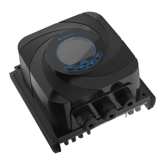
- Page 1 ONGA USER QUICK MANUAL...
-
Page 2: Safety Instructions
SAFETY INSTRUCTIONS Please read the IMPORTANT SAFETY INFORMATION below, and all Warning and Caution information elsewhere. Danger : Indicates a potentially hazardous Danger : Indicates a risk of electric shock, which, situation other than electrical, which if not if not avoided, could result in damage to the avoided, could result in damage to property. - Page 3 DISPLAY 1> LCD Display VFD Operation Parameter 1 Sensor Alarm VFD Stop VFD Alarm Parameter 2 Pump Alarm 2> LCD Color <Operation is Blue> <Stop is Purple> <Alarm is Red>...
- Page 4 SETTING 1> Switching to Constant Pressure or Constant Speed Changing to Constant Speed(MANUAL OPERATION MODE) • To set to MANUAL OPERATION MODE, press down on the STOP button for 3 seconds. The AUTO indication will disappear. In MANUAL OPERATION MODE, press the and once the indication is on Hz, change the constant speed required by pressing either the and press the...
-
Page 5: Setting Parameter
SETTING PARAMETER 1> Parameter1 Inverter Parameter First, stop the inverter, then press the button stimultaneously. Display Description Value Default (240V) P 00 Max Frequency 5.0 ~ 70.0 Hz P 01 Max Voltage Frequency 5.0 ~ 70.0 Hz P 02 Max Voltage 50 ~ 240 VAC P 03 Mid-Point Frequency... -
Page 6: Specification
SPECIFICATION INJ-4500L Model Number Insulation Class IP55 0.75 Max. Applicable Motor Output Max linkage inverter Rated Input AC Voltage 2Phase(2line)220/240V(±10%), 50/60Hz(±5%) Rated Output Voltage (V) 3Phase220/240V Rated Output Current (A) Control System PWM Type 0~120Hz Output Frequency Range Torque Characteristics V/F Control (Regular Torque, Low Deceleration Torque) Overload Endurance 150% of rated current for 1 minute... - Page 7 ALARM LOG & CONFIRMATION Alarm Log (Max 20 logs) In Main display, Press the button longer and together. Display Alarm Reason Countermeasures Over-current on the inverter/ If problem repeats/ Over current Abnormal operation of the motor/ Check the pump/motor Short of the motor’s output line Low voltage Low-voltage on the inverter Check the input voltage...
- Page 8 NOTES...
- Page 9 NOTES...
- Page 10 NOTES...
- Page 11 NOTES...
Need help?
Do you have a question about the ONGA INTELLIMASTER INJ-4500L 075 and is the answer not in the manual?
Questions and answers