Table of Contents
Advertisement
Quick Links
TM
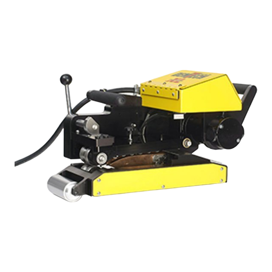
Model: Pro-Wedge 3XL
Part Number: 500-0100/3XL/A
Geo-membrane Wedge Welder
Operator's Manual
Revision: A
Scope of Manual: This manual contains procedures for safety, general unpacking,
installation, setup and operation of your DEMTECH Services, Inc. Pro-Wedge 3XL
TM
.
DEMTECH Services, Inc.
Ship to address: 6414 Capitol Avenue
Diamond Springs, CA 95619 U.S.A.
Advertisement
Table of Contents

Related Manuals for Demtech Pro-Wedge 3XL


Summary of Contents for Demtech Pro-Wedge 3XL
- Page 1 Operator’s Manual Revision: A Scope of Manual: This manual contains procedures for safety, general unpacking, installation, setup and operation of your DEMTECH Services, Inc. Pro-Wedge 3XL DEMTECH Services, Inc. Ship to address: 6414 Capitol Avenue Diamond Springs, CA 95619 U.S.A.
- Page 2 Use of this software does not authorize de-compiling, disassembling or reverse engineering to gain access to the program code. DEMTECH Services, Inc. does not authorize any copying, changing, or other use of this software.
-
Page 3: Table Of Contents
500-0100/3XL/A, Assembly, Pro-Wedge 3XL (Front) ........26 9.2. 500-0100/3XL/A, Assembly, Pro-Wedge 3XL (Rear) ........27 9.3. 500-0100/3XL/A, Assy, Pro-Wedge 3XL (Parts List, Items 1-44) .....28 9.4. 500-0100/3XL/A, Assy, Pro-Wedge 3XL (Parts List, Items 45-87) ....29 9.5. 500-1005XL/A, Assembly, Pro-Wedge XL Controller Housing ......31 9.6. - Page 4 9.15. 500-120.6/3XL/A, Assembly, Contour Roller, Lower ........43 9.16. 500-120.6/3XL/A, Assy, Contour Roller, Lower (Parts List) ......44 9.17. 500-120.7/3XL/A, Assembly, Contour Roller, Lower ........45 9.18. 500-120.7/3XL/A, Assy, Contour Roller, Lower (Parts List) ......46 10. Product Warranty ....................47 Pro-Wedge 3XL Manual Pro-Wedge 3XL Operator’s Manual...
-
Page 5: Safety Precautions
(ESD) sensitive circuit boards. Assume that all circuit boards are sensitive to potential damage from ESD. CAUTION 4: Unauthorized personnel should not remove from the equipment those panels that are provided for protection and/or require a tool to remove. Pro-Wedge 3XL Operator’s Manual Pro-Wedge 3XL Manual... -
Page 7: General Safety & Maintenance Information
However, improper use or abuse may lead to hazardous conditions for the user or other personnel or cause damage to the welder. Always keep this manual with the welder at or near the location where the Pro-Wedge 3XL is being used for quick and easy reference. -
Page 8: Maintenance
The technician assigned to operate this welder must have read through and become familiar with this manual, particularly all safety information, before using the Pro-Wedge 3XL. No changes and/or modifications should be made to the Pro-Wedge 3XL especially as it relates to safety. -
Page 9: General Product Data
2. General Product Data The DEMTECH Services, Inc. Pro-Wedge 3XL Geo-Membrane Wedge Welder, hereinafter referred to as the Pro-Wedge 3XL or welder, dramatically speeds the welding of plastic sheet materials through the use of its wedge heating elements and multiple pressure roller design. -
Page 10: Site Preparation
Before proceeding with the unpacking and installation instructions in the following section(s) make sure the work site is prepared and ready to install the Pro-Wedge 3XL. You should have an adequate power source capable of provided clean Alternating Current (AC) power at 220-240 Volts at the rated current. -
Page 11: Unpacking And Preparation
Please notify DEMTECH Services, Inc. or your authorized DEMTECH distributor where the product was purchased in the event of any shipping damage. c. Make note of the orientation of the equipment and packing foam inserts inside the shipping case to facilitate any repackaging requirements in the future. -
Page 12: Electrical Plug Connection
5.2. Electrical Plug Connection a. The Pro-Wedge 3XL is supplied with a power cord permanently connected to the front of the welder through a right-angle strain relief. Depending on the intended country of use the plug at the other end of the power cord will vary but in all cases must be rated for the voltage and current requirements of the welder. -
Page 13: Electrical Extension Cords
5.3. Electrical Extension Cords The Pro-Wedge 3XL is capable of welding very long seams. This ability may warrant the use of electrical extension cords. It is imperative to take into account the length and wire gauge of any extension cord used will ultimately determine the actual operating voltage of the welder. -
Page 14: Welder Set-Up
Rev A: May 2010 6. Welder Set-Up The initial set-up of the Pro-Wedge 3XL is by far the most critical aspect for proper operation of the welder. Proper set-up not only leads to quality welding results but also minimizes wear and tear on the welder itself. - Page 15 Rev A: May 2010 Diagram 1 Page 9 Pro-Wedge 3XL Operator’s Manual Pro-Wedge 3XL Manual...
-
Page 16: Adjustment #1: Wedge Centering
Using a 10mm box end wrench loosen the Locknut (2) (see Figure 1). Using a 3mm hex wrench turn the Adjustment Screw (3) (see Figure 1) counter-clockwise, lowering the Lower Contour Roller Assembly (4) (see Figure 1) away from the Wedge. Figure 1 Pro-Wedge 3XL Manual Pro-Wedge 3XL Operator’s Manual Page 10... - Page 17 Using a 10mm box end wrench loosen the Locknut (1) (see Figure 2) on the Upper Contour Roller Adjustment Knob. Turn the Adjustment Knob (2) (see Figure 2) counter- clockwise, raising the Upper Contour Roller Assembly (3) (see Figure 2) away from the Wedge. Figure 2 Page 11 Pro-Wedge 3XL Operator’s Manual Pro-Wedge 3XL Manual...
- Page 18 Pressure Cam (2) (see Figure 3) to the corresponding mil thickness position indicated on the side of the Pressure Cam by rotating the Nip Pressure Cam Lever (3) (see Figure 3) clockwise. Figure 3 Pro-Wedge 3XL Manual Pro-Wedge 3XL Operator’s Manual Page 12...
- Page 19 Wedge Height Adjustment Screw (2) (see Figure 4) as needed, up or down, to center the Wedge between the Nip Rollers. Turning the Adjustment Screw clockwise raises the Wedge, counter-clockwise lowers it. Figure 4 Page 13 Pro-Wedge 3XL Operator’s Manual Pro-Wedge 3XL Manual...
-
Page 20: Adjustment #2: Wedge Engagement Position
If it does tighten the Pinion Gear Set Screw (1) (see Figure 5). This adjustment controls how close the Wedge is to the Nip Rollers when it is in the Engaged/Welding position. Figure 5 Pro-Wedge 3XL Manual Pro-Wedge 3XL Operator’s Manual Page 14... - Page 21 UPPER CONTOUR ROLLER ASSY DISTANCE #1 DOUBLE THICKNESS OF UPPER MATERIAL TO BE WELDED NIP ROLLER WEDGE LOWER NIP ROLLER LOWER CONTOUR ROLLER ASSY DISTANCE #3 (SAME AS DISTANCE #1) Diagram 2 Page 15 Pro-Wedge 3XL Operator’s Manual Pro-Wedge 3XL Manual...
- Page 22 Firmly tighten both Hold-Down Screws then rotate the Wedge Engagement Handle counter-clockwise until the Lock-In Plunger drops into the Lock-In Hole. Verify that the Wedge engaged position did not change during this procedure. Pro-Wedge 3XL Manual Pro-Wedge 3XL Operator’s Manual Page 16...
-
Page 23: Adjustment #3: Upper And Lower Contour Rollers
Once the desired tension is achieved tighten both Upper and Lower Contour Roller Assembly Locknuts being careful not to over-tighten, replace the Lower Contour Roller Adjustment Cover remove all material pieces from welder. Page 17 Pro-Wedge 3XL Operator’s Manual Pro-Wedge 3XL Manual... - Page 24 ROLLER ASSY UPPER NIP ROLLER WEDGE LOWER NIP ROLLER LOWER CONTOUR ROLLER ASSY Diagram 3 UPPER CONTOUR ROLLER ASSY UPPER NIP ROLLER WEDGE LOWER NIP ROLLER LOWER CONTOUR ROLLER ASSY Diagram 4 Pro-Wedge 3XL Manual Pro-Wedge 3XL Operator’s Manual Page 18...
-
Page 25: Wedge Timing Definition
Repeat this process as many times as necessary until the Lock-In Plunger drops into the Lock-In Hole on the Lock-In Disc and the tip of the Wedge has approximately 1/8" clearance between it and the lower nip roller. The Wedge has now been re-timed. Page 19 Pro-Wedge 3XL Operator’s Manual Pro-Wedge 3XL Manual... - Page 26 Rev A: May 2010 Gear disengages from wedge rack. Figure 7 (Shown with side housing open for clarity.) Pro-Wedge 3XL Manual Pro-Wedge 3XL Operator’s Manual Page 20...
-
Page 27: Wedge Removal
Wedge and slowly pull the Wedge Assembly out of the welder. Note: To prevent the Wedge Timing from being changed do not disturb the Wedge Engagement Handle position while the Wedge Assembly is removed from the welder. Page 21 Pro-Wedge 3XL Operator’s Manual Pro-Wedge 3XL Manual... - Page 28 Rev A: May 2010 Figure 8 Pro-Wedge 3XL Manual Pro-Wedge 3XL Operator’s Manual Page 22...
-
Page 29: Factory Servicing
Rev A: May 2010 7. Factory Servicing In the event your Pro-Wedge 3XL should require factory service, the entire welder needs to be returned to the factory. Refer to the following step for preparing the Pro-Wedge 3XL for return. Carefully pack the Pro-Wedge 3XL in the reusable portable shipping/storage case provided with the welder for return to DEMTECH Services, Inc.’s factory for service. - Page 30 Rev A: May 2010 Diagram 5 Pro-Wedge 3XL Manual Pro-Wedge 3XL Operator’s Manual Page 24...
-
Page 31: Service/Spare Parts Id
Refer to the diagrams and related parts lists on the following pages to identify service/spare parts for the Pro-Wedge 3XL. To locate a part find it visually on one of the exploded assembly diagrams and note its item number. The item number is the upper digit in the item identification balloon. -
Page 32: 500-0100/3Xl/A, Assembly, Pro-Wedge 3Xl (Front)
Rev A: May 2010 9.1. 500-0100/3XL/A, Assembly, Pro-Wedge 3XL (Front) Pro-Wedge 3XL Manual Pro-Wedge 3XL Operator’s Manual Page 26... -
Page 33: 500-0100/3Xl/A, Assembly, Pro-Wedge 3Xl (Rear)
Rev A: May 2010 9.2. 500-0100/3XL/A, Assembly, Pro-Wedge 3XL (Rear) Page 27 Pro-Wedge 3XL Operator’s Manual Pro-Wedge 3XL Manual... -
Page 34: 500-0100/3Xl/A, Assy, Pro-Wedge 3Xl (Parts List, Items 1-44)
500-101/3XL/A ASSEMBLY, MAIN FRAME 100-399 NAME PLATE / SERIAL # PLATE 100-235 MOUNT, CONDUIT, #MS21919-WDG10 Item Part Number Title/Description Qty. Parts List 9.3. 500-0100/3XL/A, Assy, Pro-Wedge 3XL (Parts List, Items 1-44) Pro-Wedge 3XL Manual Pro-Wedge 3XL Operator’s Manual Page 28... -
Page 35: 500-0100/3Xl/A, Assy, Pro-Wedge 3Xl (Parts List, Items 45-87)
PLATE, DROP-IN 500-174 PLUNGER, HAND RETRACTABLE 500-173XL HANDLE, WEDGE ENGAGE 500-170 MOTOR, DRIVE 9.4. 500-0100/3XL/A, Assy, Pro-Wedge 3XL (Parts List, Items 45-87) 500-169/3XL SLEEVE, CAM SHAFT, 3XL 500-168.35 SPROCKET, NIP DRIVE, 10 TOOTH, MODIFIED 500-167/3XL/A ASSEMBLY, NIP ARM 500-166/3XL CAM, ADJUSTMENT, 3XL... - Page 36 Rev A: May 2010 Pro-Wedge 3XL Manual Pro-Wedge 3XL Operator’s Manual Page 30...
-
Page 37: 500-1005Xl/A, Assembly, Pro-Wedge Xl Controller Housing
Rev A: May 2010 9.5. 500-1005XL/A, Assembly, Pro-Wedge XL Controller Housing Page 31 Pro-Wedge 3XL Operator’s Manual Pro-Wedge 3XL Manual... -
Page 38: 500-1005Xl/A, Assy, Pro-Wedge Xl Cntrlr Housing (Parts List)
HINGE, CONTROLLER HOUSING 500-1005AXL GASKET, CONTROLLER HOUSING 500-1005XL HOUSING, CONTROLLER 100-475/A ASSEMBLY, POWER CORD, 120V Item Part Number Title/Description Qty. Parts List 9.6. 500-1005XL/A, Assy, Pro-Wedge XL Cntrlr Housing (Parts List) Pro-Wedge 3XL Manual Pro-Wedge 3XL Operator’s Manual Page 32... - Page 39 Rev A: May 2010 Page 33 Pro-Wedge 3XL Operator’s Manual Pro-Wedge 3XL Manual...
-
Page 40: 500-1006/3Xl/A, Assembly, Pro-Wedge 3Xl Control Panel
Rev A: May 2010 9.7. 500-1006/3XL/A, Assembly, Pro-Wedge 3XL Control Panel Pro-Wedge 3XL Manual Pro-Wedge 3XL Operator’s Manual Page 34... -
Page 41: 500-1006/3Xl/A, Assy, Pro-Wedge 3Xl Cntrl Panel (Parts List)
PANEL, CONTROL, 3XL 100-430 RELAY, #SSR-240-25A-DC1 100-425 CONTROL BOARD, TEMPERATURE, #935A-1CC0-000G 100-416 POTENTIOMETER, PUSH BUTTON, MOTOR, #754-7975 Item Part Number Title/Description Qty. Parts List 9.8. 500-1006/3XL/A, Assy, Pro-Wedge 3XL Cntrl Panel (Parts List) Page 35 Pro-Wedge 3XL Operator’s Manual Pro-Wedge 3XL Manual... -
Page 42: 500-101/3Xl/A, Assembly, Main Frame
Rev A: May 2010 9.9. 500-101/3XL/A, Assembly, Main Frame Pro-Wedge 3XL Manual Pro-Wedge 3XL Operator’s Manual Page 36... -
Page 43: 500-101/3Xl/A, Assembly, Main Frame (Parts List)
500-108XL CRADLE, WEDGE PIVOT 500-106.1XL SKID, MATERIAL 500-101.1/3XL PLATE, DROP OUT, LOWER CONTOUR ROLLER 500-101/3XL FRAME, MAIN Item Part Number Title/Description Qty. Parts List 9.10. 500-101/3XL/A, Assembly, Main Frame (Parts List) Page 37 Pro-Wedge 3XL Operator’s Manual Pro-Wedge 3XL Manual... -
Page 44: 500-167/3Xl/A, Assembly, Nip Arm
Rev A: May 2010 9.11. 500-167/3XL/A, Assembly, Nip Arm Pro-Wedge 3XL Manual Pro-Wedge 3XL Operator’s Manual Page 38... -
Page 45: 500-167/3Xl/A, Assembly, Nip Arm (Parts List)
ARM, NIP 500-130 NIP ROLLER, SPLIT, HDPE 500-120C KNOB, UPPER CONTOUR ROLLER ADJUSTMENT 500-120.7/3XL/A ASSEMBLY, CONTOUR ROLLER, UPPER Item Part Number Title/Description Qty. Parts List 9.12. 500-167/3XL/A, Assembly, Nip Arm (Parts List) Page 39 Pro-Wedge 3XL Operator’s Manual Pro-Wedge 3XL Manual... - Page 46 Rev A: May 2010 Pro-Wedge 3XL Manual Pro-Wedge 3XL Operator’s Manual Page 40...
-
Page 47: 500-125Cmplt/3000/3Xl, Assy, Wedge, Split, Complete, 3Xl
Rev A: May 2010 9.13. 500-125CMPLT/3000/3XL, Assy, Wedge, Split, Complete, 3XL Page 41 Pro-Wedge 3XL Operator’s Manual Pro-Wedge 3XL Manual... -
Page 48: 500-125Cmplt/3000/3Xl, Assy, Wedge, Split, Cmplt, 3Xl (P/L)
MOUNT, WEDGE, RIGHT HAND 500-123 SHAFT, LINEAR 500-122.1 HOUSING, WEDGE TAIL /800 500-121 RACK, GEAR, 3/8 Item Part Number Title/Description Qty. Parts List 9.14. 500-125CMPLT/3000/3XL, Assy, Wedge, Split, Cmplt, 3XL (P/L) Pro-Wedge 3XL Manual Pro-Wedge 3XL Operator’s Manual Page 42... -
Page 49: 500-120.6/3Xl/A, Assembly, Contour Roller, Lower
Rev A: May 2010 9.15. 500-120.6/3XL/A, Assembly, Contour Roller, Lower Page 43 Pro-Wedge 3XL Operator’s Manual Pro-Wedge 3XL Manual... -
Page 50: 500-120.6/3Xl/A, Assy, Contour Roller, Lower (Parts List)
DOWEL PIN, CONTOUR ROLLER ASSEMBLY, 3/16" OD X 5/8" LONG, 500-120F SPRING, CONTOUR ROLLER 500-120E.1 ROLLER, CONTOUR 500-120A/B PLATE, CONTOUR ROLLER, W/SWIVEL Item Part Number Title/Description Qty. Parts List 9.16. 500-120.6/3XL/A, Assy, Contour Roller, Lower (Parts List) Pro-Wedge 3XL Manual Pro-Wedge 3XL Operator’s Manual Page 44... -
Page 51: 500-120.7/3Xl/A, Assembly, Contour Roller, Lower
Rev A: May 2010 9.17. 500-120.7/3XL/A, Assembly, Contour Roller, Lower Page 45 Pro-Wedge 3XL Operator’s Manual Pro-Wedge 3XL Manual... -
Page 52: 500-120.7/3Xl/A, Assy, Contour Roller, Lower (Parts List)
DOWEL PIN, CONTOUR ROLLER ASSEMBLY, 3/16" OD X 5/8" LONG, 500-120E.1 ROLLER, CONTOUR 500-120A/B PLATE, CONTOUR ROLLER, W/SWIVEL Item Part Number Title/Description Qty. Parts List 9.18. 500-120.7/3XL/A, Assy, Contour Roller, Lower (Parts List) Pro-Wedge 3XL Manual Pro-Wedge 3XL Operator’s Manual Page 46... -
Page 53: Product Warranty
DEMTECH Services, Inc.'s option, a service representative may be dispatched to the equipment location. As an additional protection, DEMTECH Services, Inc. warrants that for a period of 90 days from the date of shipment to the original buyer, pending prior authorization from DEMTECH Services, Inc., there will be no charge for service related shipping of parts and/or equipment or for authorized travel of a service representative to the equipment location.
Need help?
Do you have a question about the Pro-Wedge 3XL and is the answer not in the manual?
Questions and answers