Table of Contents
Advertisement
Quick Links
Advertisement
Table of Contents

Related Manuals for Demtech Pro-X 600-0100/A Pro-X 600-0100/PRT/A


Summary of Contents for Demtech Pro-X 600-0100/A Pro-X 600-0100/PRT/A
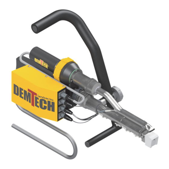
- Page 1 Pro-X Operator’s Manual Model Numbers: 600-0100/A 600-0100/PRT/A Revision: D...
- Page 2 DEMTECH Services, Inc. developments. The material in the manual is for informational purposes only and is subject to change without notice. DEMTECH Services, Inc. assumes no responsibility for any errors that may appear in this manual. Manual Number: 600-OPERATOR’S MANUAL/PRO-X, Revision: D DEMTECH Services, Inc.
-
Page 3: Table Of Contents
Rev. D, April 2021 Table of Contents SAFETY PRECAUTIONS………………………………………………….PAGE 1 GENERAL SAFETY & MAINTENANCE INFORMATION…………...PAGE 2 Intended Use………………………………………………………...Page 2 Maintenance………………………………………………………...Page 2 GENERAL PRODUCT DATA…………………………………………….PAGE 3 OPERATING ENVIRONMENT…………………………………………..PAGE 3 ... - Page 4 Rev. D, April 2021 Stop a Weld………………………………………………………….Page 14 Between Welds………………………………………………………Page 14 Checking the Output Temperature…………………………………...Page 15 Changing the Welding Shoe………………………………………….Page 16 FACTORY SERVICING…………………………………………………….PAGE 18 WELDER WIRING DIAGRAM……………………………………………PAGE 18 ...
-
Page 5: Safety Precautions
Rev. D, April 2021 1 Safety Precautions Safety precautions for operating personnel and equipment: WARNING 1: Operating personnel should perform only the procedures described and recommended in this manual. Only qualified service personnel familiar with electrical shock hazards and mechanical entanglement hazards present inside the equipment should perform disassembly or corrective maintenance of the equipment. -
Page 6: General Safety & Maintenance Information
Before removing or installing spare parts or performing other repair operations to the welder, consult DEMTECH Services, Inc. or your authorized DEMTECH service center for advice on proper procedures. This will help insure a safe and successful outcome. Always make sure all screw connections are tight before attempting to operate the welder after maintenance and/or repair procedures. -
Page 7: General Product Data
DEMTECH Services, Inc. strives to make our welders easy to use and built to last. Just like all other DEMTECH Services, Inc. products, even a first-time user will be productive in minutes. 4 Operating Environment The Pro-X is intended to be operated within the following environmental ranges and conditions. -
Page 8: Unpacking & Installation Instructions
You should consult your administration concerning claims for shipping damage. Please notify DEMTECH Services, Inc. or your authorized DEMTECH distributor where the product was purchased in the event of any shipping damage. b. Unlatch and open the shipping/storage case lid and inspect inside the case and the welder thoroughly for any signs of mishandling or damage during shipping. -
Page 9: Electrical Plug Connection
Rev. D, April 2021 e. The welder must be removed from the shipping/storage case and placed in an appropriate location suitable for the welding you intend to perform. Electrical Plug Connection a. The Pro-X is supplied with a power cord, which is permanently connected to the bottom side of the controller housing. - Page 10 If the displays power-up as described you are now ready to operate the welder. If the welder does not power-up as described please contact DEMTECH Services, Inc. or your authorized DEMTECH service center. d. The operating voltage requirement for the Pro-X is 220-240 Volts ~ (AC) only. This operating voltage range refers to the actual voltage as measured at the welder power cord plug after any extension cords while operating the welder under load.
-
Page 11: Generator Recommendations
Rev. D, April 2021 Generator Recommendations When operating the Pro-X using house power from a building circuit use the appropriate plug and power cord configuration. When in-field generators are used they must be rated for a minimum of 5,000 watts, however a rating of 6,500 watts or more is highly recommended in order to obtain the best welder performance and temperature control. -
Page 12: Welder Controls
Rev. D, April 2021 7 Welder Controls The Pro-X utilizes two temperature controllers located on the main control panel. The upper controller operates the Pre-Heat (Air) temperature, and the lower controller operates the Plastic Heat (Barrel/molten rod) temperature (see Figure 7.1). Figure 7.1 Pro-X Operator’s Manual Page 8... -
Page 13: Recommended Temperature Settings
These factors make it impractical to create a chart that can universally cover all these varying conditions: Therefore, we recommend contacting DEMTECH Services, Inc. or your authorized DEMTECH distributor where the product was purchased to receive guidance for appropriate settings. -
Page 14: Shut-Down Procedure
Rev. D, April 2021 Shut-Down Procedure When all welding operations are complete perform the following procedure to shut-down the Pro-X and ready it for storage. 1. Start the drive motor to cause one or two inches of extrudate to be pumped out of the Welding Shoe exit orifice. -
Page 15: Welder Set-Up & Operation
Rev. D, April 2021 8 Welder Set-Up & Operation The initial set-up of the Pro-X is by far the most critical aspect for proper welder operation. Proper set-up not only leads to quality welding results but also minimizes wear and tear on the welder itself. - Page 16 Rev. D, April 2021 Figure 8.1 The welder contains a cold start protection feature that prevents operation of the drill motor before the welder has reached the proper operating temperature. To prepare the welder for operation set the Pre-Heat and Plastic Heat temperatures. These settings will vary depending on the material to be welded and the ambient environment.
-
Page 17: Start A Weld
Rev. D, April 2021 Start a Weld Once the welder has stabilized at the operating temperature insert the end of the welding rod into the feed port while simultaneously powering the drill motor (see Figure 8.2). Once the welding rod starts to feed it will continue to self-feed as you weld. The welder drill motor should only be operated when welding rod is being continuously fed into the welder and should never be run dry. -
Page 18: During A Weld
Rev. D, April 2021 During a Weld Keep the welding rod being fed into the welder clean and dry. Foreign material such as dust, dirt, sand and water droplets introduced into the feed port can cause premature wear to the welder. For long welds the Pro-X drill motor has a locking pin which allows you to lock the drill motor trigger switch in the ON position. -
Page 19: Checking The Output Temperature
Rev. D, April 2021 Checking the Output Temperature The temperatures of the extruded material and pre-heat air stream should be verified at regular intervals while performing welds over an extended period. An appropriate high- speed electronic temperature meter with matching temperature probes must be used when performing these measurements. -
Page 20: Changing The Welding Shoe
Rev. D, April 2021 Changing the Welding Shoe Make sure to turn off the Pre-Heat and Plastic Heat, allow the extruder to cool to room temperature then remove the ~ (AC) line cord from the power outlet before attempting to service the equipment. - Page 21 Rev. D, April 2021 b. Remove the Shoe Assembly from the Nozzle, part number 605-017. Due to melted plastic material buildup removal may require strong twisting clockwise-to- counterclockwise, wiggling from side-to-side and substantial pulling force to remove (see Figure 8.5). P/N 600-020 Figure 8.5 c.
-
Page 22: Factory Servicing
Refer to the following step for preparing the Pro-X for return. Carefully pack the Pro-X in the reusable portable shipping/storage case provided with the welder for return to DEMTECH Services, Inc.’s factory for service. Unless previous arrangements are made, shipping charges and insurance are the responsibility of the customer. -
Page 23: 600-0100/A/Wd - Pro-X Wiring Diagram (Parts Id)
Rev. D, April 2021 11.1 600-0100/A/WD – PRO-X WIRING DIAGRAM (Parts ID) Page 19 Pro-X Operator’s Manual... -
Page 24: 600-0100/A/Wd - Pro-X Wiring Diagram (Parts List)
Rev. D, April 2021 PARTS LIST ITEM PART NO DESCRIPTION QTY 1 100‐426 CONTROLLER, TEMPERATURE, EZ‐ZONE 2 2 100‐431 RELAY, SOLID STATE, 25A, 3‐32VDC, 240V 3 3 100‐475/A ASSEMBLY, POWER CORD, 120V 1 4 600‐03A HEATER, BARREL, 530 WATT, 240 VAC 1 5 600‐03B HEATER, BARREL, 670 WATT, 240 VAC 1 6 600‐06 SWITCH, PRE‐HEAT / PLASTIC HEAT 1 7 600‐09 CURRENT INDICATOR, RED 1 8 600‐10 CURRENT INDICATOR, GREEN 1 ... - Page 25 At DEMTECH Services, Inc.'s option, a service representative may be dispatched to the equipment location. As an additional protection, DEMTECH Services, Inc. warrants that for a period of 90 days from the date of shipment to the original buyer, pending prior authorization from DEMTECH Services, Inc., there will be no charge for service related shipping of parts and/or equipment or for authorized travel of a service representative to the equipment location.