Table of Contents
Advertisement
Advertisement
Table of Contents

Related Manuals for Demtech Pro-Wedge VM-20


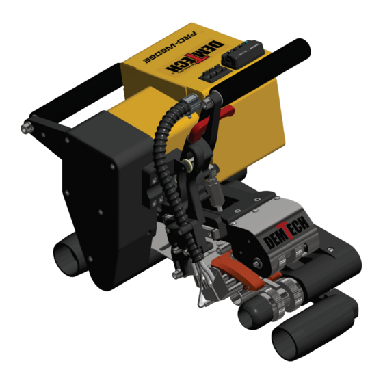
Summary of Contents for Demtech Pro-Wedge VM-20
- Page 1 Pro-Wedge VM-20 Operator’s Manual Model Number: VM-20AU/A Revision: A...
- Page 2 DEMTECH Services, Inc. developments. The material in the manual is for informational purposes only and is subject to change without notice. DEMTECH Services, Inc. assumes no responsibility for any errors that may appear in this manual. Manual Number: 100-OPERATOR’S MANUAL/VM-20/AU, Revision: A DEMTECH Services, Inc.
-
Page 3: Table Of Contents
MATERIAL SET-UP……………………………………………………….PAGE 6 7.1 Set-up Nip Pressure Adjustment…………………………………….Page 7 7.2 Set-up Upper Contour Roller Configurations……………………...Page 9 7.3 Set-up Lower Contour Roller Adjustment…………………………Page 13 WELDING PROCEDURE………………………………………………...PAGE 16 8.1 Power Up…………………………………………………………...Page 16 8.2 Setting Wedge Temperature………………………………………..Page 17 Pro-Wedge VM-20 Operator’s Manual Page iii... - Page 4 9.3 Appendix C, Pro-Wedge Lid Wiring Schematic (Parts ID)………..Page 23 9.4 Pro-Wedge Lid Wiring Schematic (Parts List)…………………….Page 24 9.5 Appendix D, Pro-Wedge Box Wiring Schematic (Parts ID)………...Page 25 9.6 Pro-Wedge Box Wiring Schematic (Parts List)……………………...Page 26 9.7 Appendix E, Warranty……………………………………………….Page 27 Pro-Wedge VM-20 Operator’s Manual Page iv...
-
Page 5: Safety Precautions
(ESD) sensitive Printed Circuit Boards (PCB’s). Assume that all PCB’s are sensitive to potential damage from ESD. CAUTION 4: Unauthorized personnel should not remove from the equipment those panels or covers that are provided for protection and/or require a tool to remove. Page 1 Pro-Wedge VM-20 Operator’s Manual... -
Page 6: General Safety & Maintenance Information
Before removing or installing spare parts or performing other repair operations to the welder, consult DEMTECH Services, Inc. or your authorized DEMTECH service center for advice on proper procedures. This will help insure a safe and successful outcome. Always make sure all screw connections are tight before attempting to operate the welder after maintenance and/or repair procedures. -
Page 7: General Product Data
Wedge has been built using the highest quality materials available which include Billet Aluminum and ground and hardened steel. DEMTECH Services, Inc. strives to make our welders easy to use and built to last. Just like all other DEMTECH Services, Inc. products, even a first time user will be productive in minutes. -
Page 8: Unpacking & Installation Instructions
You should consult your administration concerning claims for shipping damage. Please notify DEMTECH Services, Inc. or your authorized DEMTECH distributor where the product was purchased in the event of any shipping damage. b. Unlatch and open the shipping/storage case lid and inspect inside the case and the welder thoroughly for any signs of mishandling or damage during shipping. -
Page 9: Electrical Plug Connection
As a rule, higher wattage generators provide better welder performance. Keep in mind that the length and wire gauge of any extension cord being used combined with the capacity of the generator ultimately determines the operating voltage and therefore welder performance. Page 5 Pro-Wedge VM-20 Operator’s Manual... -
Page 10: Accessories
“Top” on your adjustment material at the same location that it appears on the template. Fold adjustment material so that the word “top” is visible. 2. Set of metric Allen wrenches. 3. 13mm open end wrench. 4. Phillips screw driver. Page 6 Pro-Wedge VM-20 Operator’s Manual... -
Page 11: Set-Up Nip Pressure Adjustment
Pro-Wedge from “burning out”. This can happen when the nip rollers lose traction and spin on the material, causing the Pro-Wedge to stop in the seam and burn a hole in the material. Page 7 Pro-Wedge VM-20 Operator’s Manual... - Page 12 (Figure 7.3). Check pressure by attempting to move the material side to side. If you are able to move the material or pull the material straight out without the nip rollers turning, disengage the nip pressure and turn adjustment nut Page 8 Pro-Wedge VM-20 Operator’s Manual...
-
Page 13: Set-Up Upper Contour Roller Configurations
For specific applications of the material you will be welding refer to the Upper Contour Roller Assembly Spring Configuration Chart on the following page. Page 9 Pro-Wedge VM-20 Operator’s Manual... - Page 14 PP Reinforced 30-45 mil Yes w/no backup spring Yes w/no backup spring 50-100 mil Yes w/no backup spring 20-40 mil Yes (light spring# 100-012A) Geotextiles 4-50 oz. / sq. yd. Contact Manufacturer Contact Manufacturer Page 10 Pro-Wedge VM-20 Operator’s Manual...
- Page 15 Remove the two Phillips head screws that attach the upper contour roller assembly mount plate (#1, Figure 7.5) to the nip arm and remove contour assembly from the unit. You may need to move the heating wedge fore or aft for access with screwdriver. Page 11 Pro-Wedge VM-20 Operator’s Manual...
- Page 16 Figure 7.5 The individual upper contour rollers and springs can now be configured to match the material you will be welding. See the Upper Contour Roller Assembly Spring Configuration Chart on the previous page. Page 12 Pro-Wedge VM-20 Operator’s Manual...
-
Page 17: Set-Up Lower Contour Roller Adjustment
Make sure the word “Top” is facing up then slide the material above and below the wedge and between the upper and lower contour rollers as shown above. Insert just enough in so that about 2 ¾” (70mm) of material is protruding out of the nip rollers Page 13 Pro-Wedge VM-20 Operator’s Manual... - Page 18 When adjusting, you may need to work the 4mm Allen wrench and the 6mm Allen wrench for the front contour roller (4)) or the 13mm open end wrench for the rear contour roller (3)) simultaneously to rotate the roller smoothly. Page 14 Pro-Wedge VM-20 Operator’s Manual...
- Page 19 The Auto-Engage Bracket (P/N 100-200AU/A) shown below provides the ability to adjust the heating wedge position in relation to the nip-rollers. See below for more details. Figure 7.7 Page 15 Pro-Wedge VM-20 Operator’s Manual...
-
Page 20: Welding Procedure
It is recommended that the drive motor remain on at all times while the welder is plugged in. This helps to eliminate hot spots on the nip rollers and makes starting a weld quicker and easier. Page 16 Pro-Wedge VM-20 Operator’s Manual... -
Page 21: Setting Wedge Temperature
0-32 ft/min (0-9.5 meters/min) for high speed seaming of thin materials and non-woven geotextiles. Speed versus setting values are listed for high and low gear in the speed-setting chart in Appendix B. Page 17 Pro-Wedge VM-20 Operator’s Manual... - Page 22 Rev. F, December 2020 Figure 8.1 Page 18 Pro-Wedge VM-20 Operator’s Manual...
-
Page 23: Starting A Weld
Shut-Down To shut down the Pro-Wedge, simply turn main power switch to the “off” position or unplug unit. After 5-10 minutes, place unit in shipping/storage case provided with welder. Page 19 Pro-Wedge VM-20 Operator’s Manual... -
Page 24: Reference Documents
This chart is a great reference tool, however all site conditions are different and the settings recommended on the chart may not be suitable for your specific site. Please contact a DEMTECH technical representative for advice on appropriate settings. -
Page 25: Appendix A, Pro-Wedge Welding Speed / Temperature Chart
NOTE: The above parameters are intended as a basic starting point only and will need to be adjusted to compensate for each individual ambient and site condition. Manufacturer assumes no liability for weld quality using the above parameters!! Page 21 Pro-Wedge VM-20 Operator’s Manual... -
Page 26: Appendix B, Pro-Wedge Speed Setting Versus Travel Rate Chart
19.5 16.5 16.5 16.5 13.5 13.5 13.5 10.5 10.5 10.5 Speed setting versus actual travel speed (METERS PER MINUTE) Setting Low Gear High Gear Setting Low Gear High Gear Setting Low Gear High Gear Page 22 Pro-Wedge VM-20 Operator’s Manual... -
Page 27: Appendix C, Pro-Wedge Lid Wiring Schematic (Parts Id)
Rev. F, December 2020 100-017_WH_A_2D Appendix C, Pro-Wedge Lid Wiring Schematic (Parts ID) Page 23 Pro-Wedge VM-20 Operator’s Manual... -
Page 28: Pro-Wedge Lid Wiring Schematic (Parts List)
TERMINAL, RING, 16-14 AWG, 3/6" STUD NS-HARDWARE TERMINAL, QUICK-DISCONNECT, 12-10 AWG FEMALE, FULLY INSULATED, YELLOW NS-HARDWARE TERMINAL, QUICK-DISCONNECT, 16-14 AWG FEMALE, FULLY INSULATED, BLUE NS-HARDWARE TUBING, HEAT SHRINK, FLEXIBLE, POLYOLEFIN Pro-Wedge Lid Wiring Schematic (Parts List) Page 24 Pro-Wedge VM-20 Operator’s Manual... -
Page 29: Appendix D, Pro-Wedge Box Wiring Schematic (Parts Id)
Rev. F, December 2020 100-016_WH_A_2D Appendix D, Pro-Wedge Box Wiring Schematic (Parts ID) Page 25 Pro-Wedge VM-20 Operator’s Manual... -
Page 30: Pro-Wedge Box Wiring Schematic (Parts List)
TERMINAL, QUICK-DISCONNECT, 16-14 AWG FEMALE, FULLY INSULATED, BLUE NS-HARDWARE TERMINAL, QUICK-DISCONNECT, 16-14 AWG MALE, FULLY INSULATED, BLUE NS-HARDWARE MATE-N-LOK, PIN, 16 AWG, TIN NS-HARDWARE TUBING, HEAT SHRINK, FLEXIBLE, POLYOLEFIN Pro-Wedge Box Wiring Schematic (Parts List) Page 26 Pro-Wedge VM-20 Operator’s Manual... -
Page 31: Appendix E, Warranty
At DEMTECH Services, Inc.'s option, a service representative may be dispatched to the equipment location. As an additional protection, DEMTECH Services, Inc. warrants that for a period of 90 days from the date of shipment to the original buyer, pending prior authorization from DEMTECH Services, Inc., there will be no charge for service related shipping of parts and/or equipment or for authorized travel of a service representative to the equipment location.
Need help?
Do you have a question about the Pro-Wedge VM-20 and is the answer not in the manual?
Questions and answers