Table of Contents
Advertisement
Quick Links
Advertisement
Table of Contents

Related Manuals for Demtech Pro-Wedge 3XL


Summary of Contents for Demtech Pro-Wedge 3XL
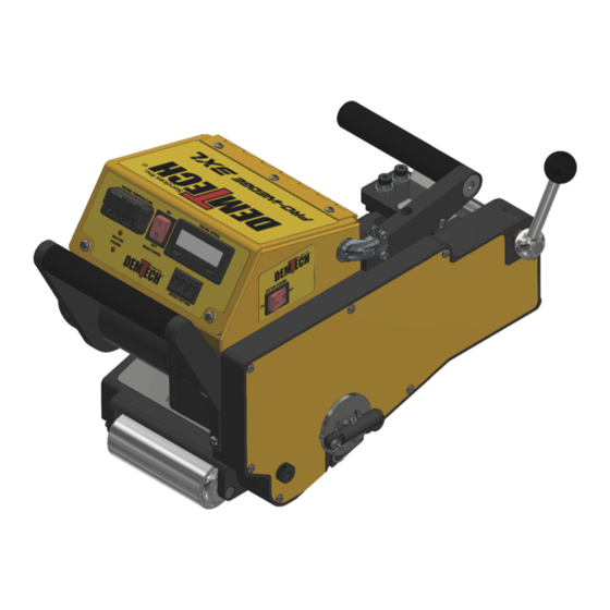
- Page 1 Pro-Wedge 3XL Operator’s Manual Model Number: 500-0100/3XL/A Revision: D...
- Page 2 Use of this software does not authorize de- compiling, disassembling or reverse engineering to gain access to the program code. DEMTECH Services, Inc. does not authorize any copying, changing, or other use of this software.
-
Page 3: Table Of Contents
Power Requirements ..................6 Generator Recommendation ................7 Extension Cords ..................7 Accessories ....................7 WELDER SET-UP .....................8 Set-Up Preparation ..................8 Adjustment #1: Wedge Centering ...............9 Pro-Wedge 3XL Operator’s Manual ... - Page 4 Wedge Timing Definition ................19 Wedge Re-Timing ..................19 Wedge Removal ..................21 FACTORY SERVICING ...................23 REFERENCE DOCUMENTS ...................23 Appendix A ....................24 Appendix B ....................25 Pro-Wedge 3XL Operator’s Manual ...
-
Page 5: Safety Precautions
Rev. E, October 2015 1 Safety Precautions Safety precautions for operating personnel and equipment: WARNING 1: Operating personnel should perform only the procedures described and recommended in this manual. Only qualified service personnel familiar with electrical shock hazards and mechanical entanglement hazards present inside the equipment should perform disassembly or corrective maintenance of the equipment. -
Page 6: General Safety & Maintenance Information
For additional product information please refer to the product data sheet. The Pro-Wedge 3XL is intended as professional use equipment and not intended for sale to the general public. The total input power of the Pro-Wedge is specified as greater than 1 kW although in lightly loaded conditions the actual power may be less than 1 kW. -
Page 7: General Product Data
Pro-Wedge has been built using the highest quality materials available which include Billet Aluminum and ground and hardened steel. DEMTECH Services, Inc. strives to make our welders easy to use and built to last. Just like all other DEMTECH Services, Inc. products, even a first time user will be productive in minutes. -
Page 8: Unpacking, Power Connection, And Accessories
Please notify DEMTECH Services, Inc. or your authorized DEMTECH distributor where the product was purchased in the event of any shipping damage. The Pro-Wedge hot wedge welder is delivered to you in a sturdy, reusable shipping/storage case. -
Page 9: Power Requirements
Using a digital voltmeter, measure the voltage under load between the hot and neutral prongs. This procedure should only be performed by a qualified electrician. Pro-Wedge 3XL Operator’s Manual Page 6... -
Page 10: Generator Recommendation
For extreme cases of sandy sub grades, an outrigger system and raised rear travel roller are available. Please contact supplier for more information and pricing. Pro-Wedge 3XL Operator’s Manual Page 7... -
Page 11: Welder Set-Up
4 inches wide by 18 inches long and three smaller pieces approximately 1/2 inch wide by 6 inches long. These five pieces of material will be used as "gauges" for setting three adjustments on the Pro-Wedge. Pro-Wedge 3XL Operator’s Manual Page 8... -
Page 12: Adjustment #1: Wedge Centering
Screw. Using a 10mm box end wrench loosen the Locknut (2) (see Figure 1). Using a 3mm hex wrench turn the Adjustment Screw (3) (see Figure 1) counter-clockwise, lowering the Lower Contour Roller Assembly (4) (see Figure 1) away from the Wedge. Pro-Wedge 3XL Operator’s Manual Page 9... - Page 13 Rev. D, November 2020 (4) 4 3 2 1 Figure 1 Pro-Wedge 3XL Operator’s Manual Page 10...
- Page 14 Contour Roller Adjustment Knob. Turn the Adjustment Knob (2) (see Figure 2) counter-clockwise, raising the Upper Contour Roller Assembly (3) (see Figure 2) away from the Wedge. 4 5 2 1 3 Figure 2 Pro-Wedge 3XL Operator’s Manual Page 11...
- Page 15 Rotate the Nip Pressure Cam (2) (see Figure 3) to the corresponding mil thickness position indicated on the side of the Pressure Cam by rotating the Nip Pressure Cam Lever (3) (see Figure 3) clockwise. 3 2 1 Figure 3 Pro-Wedge 3XL Operator’s Manual Page 12...
- Page 16 Wedge with the Wedge Height Adjustment Screw (2) (see Figure 4) as needed, up or down, to center the Wedge between the Nip Rollers. Turning the Adjustment Screw clockwise raises the Wedge, counter-clockwise lowers it. 2 1 Figure 4 Pro-Wedge 3XL Operator’s Manual Page 13...
-
Page 17: Adjustment #2: Wedge Engagement Position
If it does tighten the Pinion Gear Set Screw (1) (see Figure 5). This adjustment controls how close the Wedge is to the Nip Rollers when it is in the Engaged/Welding position. 1 Figure 5 Pro-Wedge 3XL Operator’s Manual Page 14... - Page 18 (SAME AS DISTANCE #1) UPPER CONTOUR ROLLER ASSY DISTANCE #1 DOUBLE THICKNESS OF UPPER MATERIAL TO BE WELDED NIP ROLLER WEDGE LOWER NIP ROLLER LOWER CONTOUR ROLLER ASSY DISTANCE #3 (SAME AS DISTANCE #1) Diagram 2 Pro-Wedge 3XL Operator’s Manual Page 15...
- Page 19 Lock-In Disc to move during this procedure. Firmly tighten both Hold-Down Screws then rotate the Wedge Engagement Handle counter-clockwise until the Lock-In Plunger drops into the Lock-In Hole. Verify that the Wedge engaged position did not change during this procedure. Pro-Wedge 3XL Operator’s Manual Page 16...
-
Page 20: Adjustment #3: Upper And Lower Contour Rollers
Once the desired tension is achieved tighten both Upper and Lower Contour Roller Assembly Locknuts being careful not to over-tighten, replace the Lower Contour Roller Adjustment Cover remove all material pieces from welder. Pro-Wedge 3XL Operator’s Manual Page 17... - Page 21 UPPER CONTOUR ROLLER ASSY UPPER NIP ROLLER WEDGE LOWER NIP ROLLER LOWER CONTOUR ROLLER ASSY Diagram 3 UPPER CONTOUR ROLLER ASSY UPPER NIP ROLLER WEDGE LOWER NIP ROLLER LOWER CONTOUR ROLLER ASSY Diagram 4 Pro-Wedge 3XL Operator’s Manual Page 18...
-
Page 22: Wedge Timing Definition
Lock-In Plunger drops into the Lock-In Hole on the Lock-In Disc and the tip of the Wedge has approximately 1/8" clearance between it and the lower nip roller. The Wedge has now been re-timed. Pro-Wedge 3XL Operator’s Manual Page 19... - Page 23 Rev. D, November 2020 Gear disengages from wedge rack. Figure 7 (Shown with side housing open for clarity.) Pro-Wedge 3XL Operator’s Manual Page 20...
-
Page 24: Wedge Removal
Wedge and slowly pull the Wedge Assembly out of the welder. Note: To prevent the Wedge Timing from being changed do not disturb the Wedge Engagement Handle position while the Wedge Assembly is removed from the welder. Pro-Wedge 3XL Operator’s Manual Page 21... - Page 25 Rev. D, November 2020 1 2 Figure 8 Pro-Wedge 3XL Operator’s Manual Page 22...
-
Page 26: Factory Servicing
Refer to the following step for preparing the Pro-Wedge for return. Carefully pack the Pro-Wedge in the reusable portable shipping/storage case provided with the welder for return to DEMTECH Services, Inc.’s factory for service. Unless previous arrangements are made shipping charges and insurance are the customer's responsibility. Ship the Pro-Wedge to DEMTECH Services, Inc. - Page 27 Rev. D, November 2020 Appendix A Diagram 5 Pro-Wedge 3XL Operator’s Manual Page 24...
- Page 28 As an additional protection, DEMTECH Services, Inc. warrants that for a period of 90 days from the date of shipment to the original buyer, pending prior authorization from DEMTECH Services, Inc., there will be no charge for service related shipping of parts and/or equipment or for authorized...
Need help?
Do you have a question about the Pro-Wedge 3XL and is the answer not in the manual?
Questions and answers