
Subscribe to Our Youtube Channel
Related Manuals for GEA VARIVENT TSVN


Summary of Contents for GEA VARIVENT TSVN
- Page 1 Hygienic valves ® GEA VARIVENT Sampling valve type TSVN and TSVN Operating instruction (Translation from the original language) 430BAL008565EN_1...
- Page 2 EU Machinery Directive. This document is protected by copyright. All rights reserved. The document may not, in whole or in part, be copied, reproduced, translated or reduced to an electronic medium of machine-readable form without the express permission of GEA Tuchenhagen GmbH. LEGAL NOTICE Word marks ®...
-
Page 3: Table Of Contents
TABLE OF CONTENTS General Information Information on the Document 1.1.1 Binding Character of These Operating Instructions 1.1.2 Notes on the Illustrations 1.1.3 Symbols and Highlighting Manufacturer address Contact EU Declaration of Conformity in accordance with the EC Machinery Directive 2006/42/EC Translated copy of the EU - Declaration of conformity in accordance with the Pressure Equipment Directive 2006/42/EU Safety... - Page 4 Valve TSVU without bellows Valve TSVU with bellows 9.5.3 Removing the handwheel Valve TSVN Valve TSVU Maintenance 9.6.1 Cleaning the valve 9.6.2 Replacing seals 9.6.3 Lubricating seals and threads Installation 9.7.1 O-Ring on the valve disk 9.7.2 Fitting the piston 9.7.3 Fitting position Alarms...
-
Page 5: General Information
General Information Information on the Document General Information Information on the Document The present Operating Instructions are part of the user information for the product. The Operating Instructions contain all the information you need to transport, install, commission, operate and carry out maintenance for the product. 1.1.1 Binding Character of These Operating Instructions These Operating Instructions contain the manufacturer's instructions to the... -
Page 6: Manufacturer Address
Second step in a sequence of operations. ® Result of the previous operation. ® The operation is complete, the goal has been achieved. Hint! Further useful information. Manufacturer address GEA Tuchenhagen GmbH Am Industriepark 2-10 21514 Büchen Contact Tel.:+49 4155 49-0 Fax:+49 4155 49-2035 flowcomponents@gea.com www.gea.com 430BAL008565EN_1 21.03.2022... -
Page 7: Eu Declaration Of Conformity In Accordance With The Ec Machinery Directive 2006/42/Ec
General Information EU Declaration of Conformity in accordance with the EC Machinery Directive 2006/42/EC EU Declaration of Conformity in accordance with the EC Machinery Directive 2006/42/EC 430BAL008565EN_1 21.03.2022... -
Page 8: Translated Copy Of The Eu - Declaration Of Conformity In Accordance With The Pressure Equipment Directive 2006/42/Eu
Translated copy of the EU - Declaration of conformity in accordance with the Pressure Equipment Directive 2006/42/EU Translated copy of the EU - Declaration of conformity in accordance with the Pressure Equipment Directive 2006/42/EU Manufacturer: GEA Tuchenhagen GmbH Am Industriepark 2-10 21514 Büchen We hereby declare that the machine named below... -
Page 9: Safety
Pressure Equipment Directive which specifies sound engineering practice. Nominal diameters ≥ IPS 4“; DN 125 valid for the fluid group II. In the event of any deviations, GEA Tuchenhagen GmbH will supply a specific Declaration of Conformity. Operator’s Duty of Care The operating company of the component has a special responsibility for the proper and safe handling of the component within their company. -
Page 10: Subsequent Changes
EC Machinery Directive on your own. In general, only original spare parts supplied by GEA Aseptomag AG should be fitted. This ensures the reliable and economical operation of the valve. -
Page 11: 2.4.1.1 Safety Instructions
Safety General safety instructions and dangers • Only use the valve for its intended use. • The valve must be functional and in good working order. Check the condition of the valve before starting work and at regular intervals. • Wear tight-fitting work clothing for all work on the valve. -
Page 12: Electrical Equipment
Safety Supplementary Regulations 2.4.3 Electrical Equipment For all work on electrical equipment, the following principles apply: • Access to electrical equipment should only be allowed to qualified electricians. Always keep unattended switch cabinets locked. • Modifications of the control system can affect the safe and reliable operation. Modifications are only permitted with the express permission of the manufacturer. -
Page 13: Safety Equipment
Safety Safety equipment • Received instruction about operating sequences on the component. • Familiar with the safety devices and their function. • Familiar with these Operating Instructions, especially with the safety instructions and the information which is relevant for the task on hand. •... - Page 14 Safety Signs on the valve Sign Meaning General hazard warning Fig.1 Warning crushing Fig.2 Explosion-hazarded zones warning Fig.3 430BAL008565EN_1 21.03.2022...
-
Page 15: Transport And Storage
Transport and storage Scope of supply Transport and storage Scope of supply On receipt of the valve check whether • the details on the type plate correspond to the data in the order and delivery documents, • the equipment is complete and all components are in good order. Transport For transport, the following principles apply: •... -
Page 16: Technical Data
Technical data Type plate Technical data Type plate The type plate clearly identifies the valve. Fig.4: Type plate The type plate provides the following key data: Key data of the valve Type Sampling Valve TSVN Serial Serial number Material EPDM (FDA) Control air pressure bar/psi min. -
Page 17: Resistance And Permitted Operating Temperature Of The Sealing Materials
The maximum operating temperature is defined by the sealing type and its mechanical load. Due to the versatile conditions of use (e.g. usage duration, switching frequency, type and temperature of product and cleaning agents as well as usage environment), GEA Tuchenhagen recommends that the user carries out resistance tests. Resistance: •... - Page 18 Technical data Resistance and permitted operating temperature of the sealing materials • – = no resistance Table of sealing resistance / permitted operating temperature Maximum Sealing materials Medium operating EPDM HNBR PTFE temperatures Alkalis up to 3% up to 80 °C (176°F) Alkalis up to 5% up to 40 °C (104°F) Alkalis up to 5%...
-
Page 19: Pipe Ends (R)
Technical data Pipe ends (R) Pipe ends (R) Fig.5: Sampling valve TSVN: I-Line_Housing (I), pipe ends (R) Dimensions for tubes in DN Size TSVN/TSVU Pipe ends (R) Dimensions Size 50/40 19x1.5 DN15 35/25 13x1.5 DN10 Lubricants Lubricants Designation Material no. Rivolta F.L.G. -
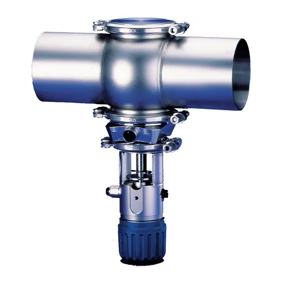
Page 20: Description
Description Design of the valve Description Design of the valve Fig.6: Main components on the valve Designation Seal ring Seal disk Sampling housing Sampling lantern Valve disk Piston rod 430BAL008565EN_1 21.03.2022... - Page 21 Description Designation 17.1 Piston Spring cage cover Compression spring Handwheel Contact disk Screw-in plug connection Lock washer 28, 30 Hinged clamp Vent screw Housing Hinged clamps 430BAL008565EN_1 21.03.2022...
-
Page 22: Assembly And Installation
Assembly and installation Safety instructions Assembly and installation Safety instructions Hazardous situations during installation can be avoided by safety-conscious and proactive behaviour of the personnel. For installation, the following principles apply: • Only qualified personnel are allowed to set-up, install and commission the component. -
Page 23: Welding In A Valve With Pipe Connection
Assembly and installation Welding In a Valve with Pipe Connection Welding In a Valve with Pipe Connection 6.4.1 Valve with Welded Ends This section describes the welding procedure for the valve housing. Warning! Spring tension in the valve Danger of injury when opening the clamp connections on the actuator or on the housing as the released spring pretension will suddenly lift the actuator. - Page 24 Assembly and installation Hint! Welding method: We recommend using the automatic orbital welding method. All welding work should only be performed by certified welders or machine operators (orbital welders). Housing O-rings: When assembling the valve always replace the housing O-rings to ensure that the valve is tight. 430BAL008565EN_1 21.03.2022...
-
Page 25: Start-Up
Start-up Safety instructions Start-up Safety instructions Initial commissioning For initial commissioning, the following principles apply: • Take protective measures against dangerous contact voltages in accordance with pertinent regulations. • The valve must be completely assembled and correctly adjusted. All screw connections must be securely tightened. -
Page 26: Cleaning And Passivation
Cleaning and Passivation Cleaning Cleaning and Passivation Cleaning All parts in contact with product must be cleaned at regular intervals. Always observe the safety data sheets issued by the cleaning agent manufacturers. Only use cleaning agents which do not cause damage to the seals and the inner parts of the valve. -
Page 27: Passivation
Cleaning and Passivation Passivation We recommend a flow velocity of at least 2 m/s. Passivation Before commissioning a plant, passivation is commonly carried out for long pipes and tanks. Valve blocks are usually excepted from this. Passivation is typically performed using nitric acid (HNO ) at approx. -
Page 28: Maintenance
Maintenance Safety instructions Maintenance Safety instructions Maintenance and repair Before carrying out maintenance and repair work on the component's electrical equipment, perform the following steps in accordance with the "5 safety rules": • Isolate from the power supply • Take appropriate measures to prevent switch on •... -
Page 29: Inspections
Maintenance Inspections • Disconnect all power and utility lines. • Markings, e.g. on lines, must not be removed. • Do not climb on the component. Use suitable access aids and working platforms. • Mark the lines (if unmarked) prior to disassembly to ensure they are not confused when re-assembling. -
Page 30: Prior To Removal
Maintenance Prior to removal Guideline Values for Maintenance Intervals Maintenance intervals Applications (guideline values) Media at temperatures of 60 °C to 130 °C approx. every 3 months (140 °F to 266 °F) Media at temperatures of < 60 °C approx. every 12 months (<... -
Page 31: Removing The Valve
Maintenance Disassembling the Valve 9.5.1 Removing the valve Fig.7 Carry out the following steps: Hold the valve. Remove the clamps (C). Take the valve out of the pipe. ® Done. 9.5.2 Removing the valve disk 430BAL008565EN_1 21.03.2022... -
Page 32: 9.5.2.1 Valve Tsvu Without Bellows
Maintenance Disassembling the Valve 9.5.2.1 Valve TSVU without bellows Fig.8: Removing the valve disk, valve without bellows Carry out the following steps: Turn the handwheel (20) counterclockwise. – The valve disc (15) is raised. Remove the hinged clamp (28) between housing (8) and lantern (9). Withdraw the valve insert from the housing (8). -
Page 33: 9.5.2.2 Valve Tsvu With Bellows
Maintenance Disassembling the Valve 9.5.2.2 Valve TSVU with bellows Fig.9: Removing the valve disk, valve with bellows Carry out the following steps: Turn the handwheel (20) counterclockwise. – The valve disc (15) is raised. Remove the hinged clamp (28) between housing (8) and lantern (9). Withdraw the valve insert from the housing (8). -
Page 34: 9.5.3.2 Valve Tsvu
Maintenance Disassembling the Valve Fig.10: Removing the handwheel valve TSVN Carry out the following steps: Turn the handwheel (20), together with piston rod (16), lock washers (27), compression spring (19), spring cage cover (18), O-rings (22, 23), piston (17) and bush (34), out of the lantern (9). Tension the compression spring (19) using the assembly tool (A), material no. -
Page 35: Maintenance
Maintenance Maintenance Pull out the piston rod (16), lock washers (27), compression spring (19), spring cage cover (18), O-rings (22, 23) and piston (17). Tension the compression spring (19) using the assembly tool, material no. 222-601.51. Pull off the lock washer (27). Use the assembly tool (A), material no. - Page 36 PARALIQ GTE 703 can be ordered from GEA Tuchenhagen under mat. no. 413-064, and Rivolta F.L.G. MD-2 can be ordered under mat. no. 413-071 from GEA Tuchenhagen. Using other types of grease can result in malfunctions or in premature seal failure.
-
Page 37: Installation
Maintenance Installation Installation Assemble the valve in reverse order of disassembly. Observe the notes and instructions given in the following sections when doing so. 9.7.1 O-Ring on the valve disk Carry out the following steps: Fit the O-ring for the valve disk (7) without applying any grease. –... -
Page 38: Alarms
Alarms Malfunctions and remedies Alarms 10.1 Malfunctions and remedies In the event of malfunctions immediately deactivate the valve and secure it against inadvertent reactivation. Malfunctions may only be remedied by qualified staff, who must observe the safety precautions. Malfunction Cause Remedy Dirt/foreign material between Clean valve housing and valve... -
Page 39: Decommissioning
Decommissioning Safety precautions Decommissioning 11.1 Safety precautions For shutting down, the following principles apply: • Switch off the compressed air. • Switch off the component with the main switch. • Padlock the main switch (if fitted) in the off position to prevent it from being switched back on. -
Page 40: Appendix
Appendix Lists Appendix 12.1 Lists 12.2 Abbreviations and terms Abbreviation Explanation British Standard Unit of measurement of pressure [bar] All pressure data expressed in [bar/psi] is assumed to be gauge pressure [barg/psig] unless explicitly specified otherwise. approx. approximately °C Unit of measurement of temperature [degree Celsius] valve coefficient, non-metric flow coefficient, see K Unit of measurement of volume [cubic decimetre] standard volume (standard litres) - Page 41 Appendix Abbreviation Explanation µm Unit of measurement of length [micrometre] Metric Unit of measurement of work [newton metre] TORQUE SPECIFICATION: 1 Nm = 0.737 lb-ft Pound-Force (lb)× Feet (ft) Polyamide PE-LD Low-density polyethylene Polytetrafluoroethylene Anglo-American unit of measurement for pressure [pound- force per square inch] All pressure data expressed in [bar/psi] is assumed to be gauge pressure [barg/psig] unless explicitly specified...
-
Page 42: Spare Parts List - Sampling Valve Tsvn
Spare parts list - Sampling valve TSVN" Spare parts list - Sampling valve TSVN" Fig.13 430BAL008565EN_1 21.03.2022... - Page 43 Spare parts list - Sampling valve TSVN" Item Designation Material DN 25 DN 32 DN 40 DN 50 Seal ring EPDM 924-255 924-255 924-255 924-255 924-297 924-297 924-297 924-297 Bearing PTFE/carbon 935-037 935-037 935-037 935-037 Bearing, 3A SUSTA-PVDF 935-097 935-097 935-097 935-097 Sealing washer I...
- Page 44 Spare parts list - Sampling valve TSVN" Item Designation Material DN 25 DN 32 DN 40 DN 50 2'' OD 1.4404 221-102.54 221-102.54 2.5'' OD 1.4404 221-102.63 221-102.63 3'' OD 1.4404 221-102.64 221-102.64 4'' OD 1.4404 221-102.65 221-102.65 2'' IPS 1.4404 221-102.62 221-102.62...
-
Page 45: Dimension Sheet - Varinline ® Sampling Valve, Type Tsvn
® Dimension sheet - VARINLINE Sampling valve, type TSVN ® Dimension sheet - VARINLINE Sampling valve, type TSVN Fig.14 430BAL008565EN_1 21.03.2022... - Page 46 ® Dimension sheet - VARINLINE Sampling valve, type TSVN Nominal Process Actuato Pipe Housing Size Valve width connection Ø Ø1 Stroke Weight [mm] [mm] [mm] [mm] [mm] [mm] [mm] [kg] DN 25 29.0 x 1.50 13 x 1.5 90.0 193.0 205.0 DN 40 41.0 x 1.50...
- Page 47 ® Dimension sheet - VARINLINE Sampling valve, type TSVN 430BAL008565EN_1 21.03.2022...
Need help?
Do you have a question about the VARIVENT TSVN and is the answer not in the manual?
Questions and answers